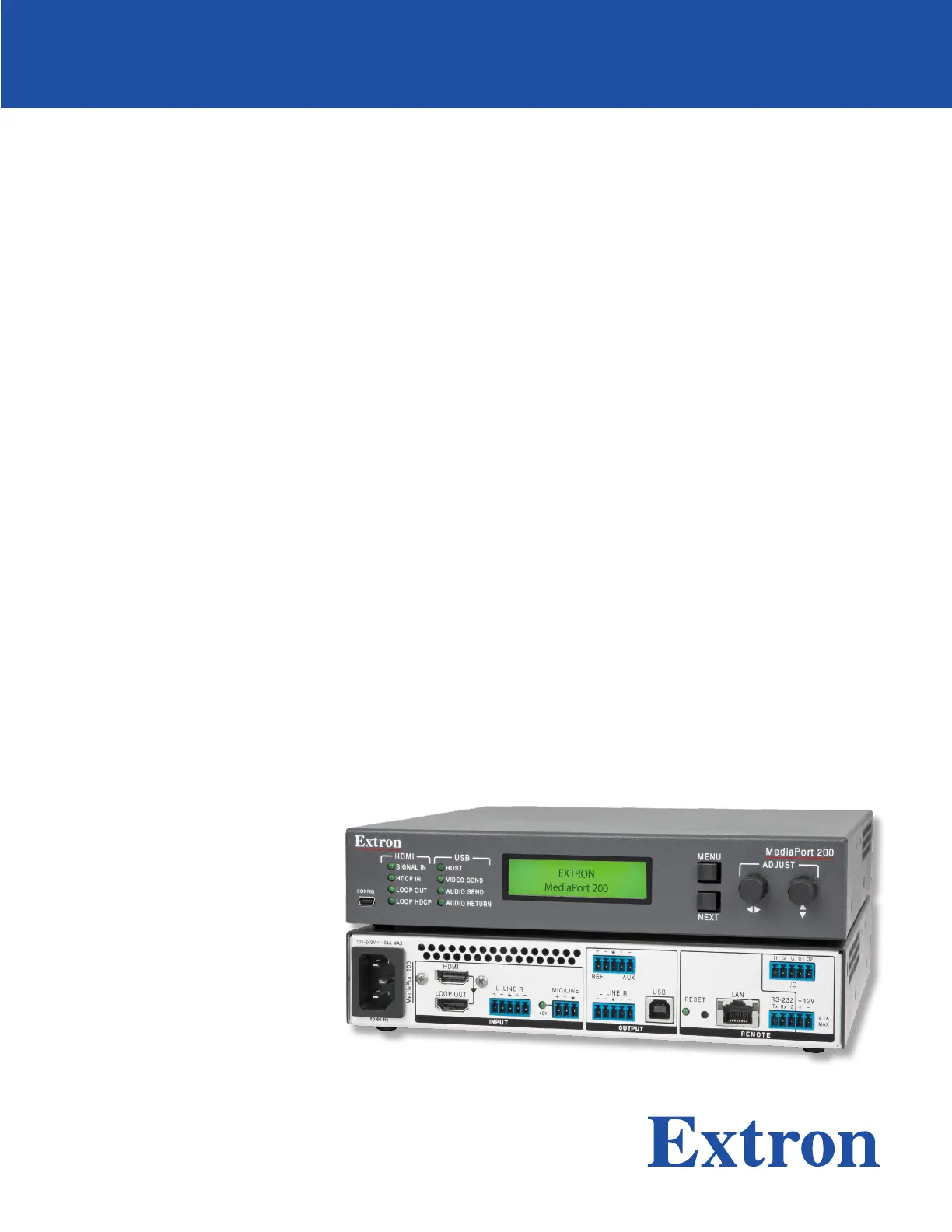
Extron MediaPort 200 Manual

Extron Ikke kategoriseret MediaPort 200

Læs gratis den danske manual til Extron MediaPort 200 (4 sider) i kategorien Ikke kategoriseret. Denne vejledning er vurderet som hjælpsom af 32 personer og har en gennemsnitlig bedømmelse på 4.4 stjerner ud af 16.5 anmeldelser. Har du et spørgsmål om Extron MediaPort 200, eller vil du spørge andre brugere om produktet?

Side 1/4
1
IMPORTANT:
Go to www.extron.com for the complete
user guide,
installation instructions,
and
specifications bef
ore connecting the
pr
oduct to the po
wer source.
MediaPort 200 HDMI and Audio to USB Scaling
Bridge • Setup Guide
The MediaPort 200 is an HDMI and audio to USB scaling bridge that interfaces between pro AV equipment and computer-based
video conferencing software. Incoming HDMI video is scaled and output via USB to a host computer. Bi-directional audio is
supported over the USB bus, including two stereo pairs from the PC for application playback and far-end communication audio,
and one stereo pair to the PC for local audio to be sent to the far end. Digital and analog audio inputs and outputs include a full
range of DSP optimization features, including filtering, EQ, ducking, compressors, and limiters. Setup and control are available via
front panel controls with an LCD menu, a front panel USB Configuration port, a rear panel RS-232 port, and a rear panel Ethernet
port. SIS (Simple Instruction Set) commands and Windows®-based software configuration simplify initial configuration and real-
time control. The 1U high, half rack wide, 9.5 inches (24.1 cm) deep enclosure can be optionally mounted to a rack shelf, or under
or through furniture.
This setup guide provides step-by-step instructions for an experienced user to set up and configure a MediaPort 200.
NOTE: For full installation, configuration, menu, connector wiring, and operation details, see the , MediaPort 200 User Guide
available at www.extron.com.
Installation
Rear Panel Features
MediaPort 200
100-240V 0.4A MAX
50-60 Hz
HDMI
LOOP OUT
MIC/LINE
+48V
LINE
L R LINE
L R
REMOTE
OUTPUT
LAN
USB
REF AUX
RESET
RS-232 +12V
I/O
Tx
0.1A
MAX
Rx G
I1 I2 G O1 O2
INPUT
II
HH
GGDD
CC
AA EE KK
JJ
LL
MM
BB
FF
A AC power connector F AEC REF and AUX audio output J Reset button
B HDMI video input connector connector K LAN connector
C HDMI video loop out connector G Line level audio output L RS-232 and +12 V power
D Line level audio input connector connector connector
E Mic/Line audio output connector H USB host connector M Digital I/O connector
and phantom power LED I Reset LED
Figure 1. MediaPort 200 Rear Panel
Mounting and Cabling the MediaPort 200
1. Disconnect power Turn off or disconnect all equipment power sources.
2. Mount the unit — (Optional) Mount the MediaPort 200 either in a rack using shelf mounting brackets such as Extron
RSU 129 or RSB 129, or under furniture using furniture mounting brackets (MBU 125). A false half-rack plate can t next to
the unit if desired.
3. Connect the HDMI input Connect an HDMI video source to the HDMI input connector (see gure 1, B). Use the
included LockIt® brackets to secure the connector in place.
4. Connect analog audio input
zConnect an analog audio
input source to the 5-pole
captive screw Line audio input
connector (D) for balanced or
unbalanced stereo audio. Wire
as shown at right.
zConnect a balanced or unbalanced microphone or
mono line level input to the 3-pole Mic/Line captive
screw connector (E). Wire as shown at right. Balanced Audio Output Unbalanced Audio Output
Tip
Slee
ve
Ring Tip
Sleeve
Unbalanced Stereo InputBalanced Stereo Input
Tip
Ring
Tip
Ring
Slee sve
Do not tin the wires!
Tip
Sleeve
Sleeve
Tip
L R
L R
inch (5 mm)
MAX.
MediaPort 200 • Setup Guide (Continued)
2
5. Connect the USB output — Connect a USB type A to B cable from the rear panel bidirectional USB B port (see figure 1,
H) to a USB type A port of a PC or Mac computer for video and audio input and output. The USB Host LED lights when this
connection is made.
6. Connect to the HDMI loop output — (Optional) Connect a local monitor or a video conferencing hardware device to the
HDMI Loop Out connector (C).
7. Connect audio output — Connect
an amplier or other output device
to the 5-pole captive screw Line
output connector (G) for balanced
or unbalanced, stereo or dual mono,
analog program output. Wire as shown at right.
8. Connect devices for configuration and control
zRS-232 For serial control, connect a host computer or other
control device to the Tx, Rx, and G pins of the 5-pole RS-232
and +12 V captive screw connector (L). Wire as shown at
right.
z+12 V power (Optional) Connect a device requiring DC
power (such as a digital I/O device that illuminates LEDs for
a microphone or switch plate) to the + and – pins of the 5-pole
control connector (L).
zUSB Config — Connect a host computer to the front panel
USB mini B port (see gure 2, C, below) for conguration via
SIS commands or the Extron PCS software.
9. Connect the MediaPort to the network Connect an Ethernet
cable between the LAN port (see gure 1, K) and the network to
congure and control the MediaPort from a remote location using
SIS commands, the PCS software, or the embedded Web page.
10. Connect an AEC reference (optional) — Connect the +, –, and
¤ (ground) REF pins of the 5-pole REF/AUX connector (F) to an
external DSP processor to use as the reference for acoustic echo
cancellation. The Ref output matches the audio received via the
USB communication input (far end audio) to the USB communications input.
11. Connect an auxiliary device — (Optional) Connect the Aux +, –, and (ground) pins of the ¤
REF/AUX connector (F) to an external DSP processor or a video conferencing hardware device, to
which mic/line audio will be sent. The Aux output matches the audio applied to the Mic/Line input.
12. Connect devices to the Digital I/O ports — (Optional) Connect a microphone or other contact closure or tally device to
the 5-pole Digital I/O captive screw connector (M). The digital input ports are labeled I1 and I2. The output ports are O1 and
O2. The middle pin, labeled G, is the shared ground. Wire inputs to
pins I1 and I2 and outputs to pins O1 and O2. Connect the ground
wires of all devices to the G pin (see the illustration at right).
13. Connect power to the MediaPort 200 AC power connector (A).
14. Apply power to all connected devices.
Front Panel Overview
MediaPort 200
CONFIG
NEXT
MENU
ADJUST
HDMI
SIGNAL IN
HDCP IN
LOOP OUT
LOOP HDCP
USB
HOST
VIDEO SEND
AUDIO SEND
AUDIO RETURN
EE
FF
AA BB CC DD
GG
Figure 2. MediaPort Front Panel
A
USB Config port C
USB LEDs E Menu button G
Next button
B HDMI LEDs D
LCD screen F Adjust knobs
RS-232
Computer
RS-232 Po
rt
MediaPort 200 Rear Panel
RS-232 Port
NOTES:
If you use cable that has a drain wire, tie
the drain wire to ground at both ends.
Connect a ground wire between the
MediaPort and the computer.
1 2 3
Tx Rx G
+12V
+ –
Ground (G)
Transmit (Tx)
Receive (Rx) Transmit (Tx)
Receive (Rx)
REF XAU
REF
AUX
Input 1 (I1)
Input 2 (I2)
Ground (G)
Output 1 (O1)
Output 2 (O2)
I/O
I1
I2
G
O1
O2
Do not tin the wires!
Balanced Audio Output
Tip
Ring
Tip
Ring
Slee
ves
Unbalanced Audio Output
Tip
No Ground Here
No Ground Here
Tip
Slee sve
L R
L R


Produkt Specifikationer

Mærke: Extron
Kategori: Ikke kategoriseret
Model: MediaPort 200

Har du brug for hjælp?

Hvis du har brug for hjælp til Extron MediaPort 200 stil et spørgsmål nedenfor, og andre brugere vil svare dig


Ikke kategoriseret Extron Manualer

Ikke kategoriseret Manualer

Nyeste Ikke kategoriseret Manualer