MGP 641 xi 5K Series • Setup Guide
IMPORTANT NOTE:
Go to www.extron.com for the complete MGP 641 xi 5K Series user guide, installation instructions, and
specications before connecting the product to the power source.
The MGP 641 xi 5K and MGP 641 xi 5K SDI are multi-window video signal processors that display multiple video sources on a
single screen in picture-in-picture or picture-by-picture format. Both models have four HDMI inputs, one HDMI background input,
one HDMI output, and one buered DTP3 output. In addition, the MGP 641 xi 5K SDI model has four 12G-SDI inputs that are
congurable to be used instead of the HDMI input. Each input is dedicated to one window.
The MGP 641 xi 5K Series feature dedicated connectivity for each of the four windows, fully customizable window layouts, HDCP
1.4 and 2.3 support, logo and background image support, logo keying, and ultra-high resolution support up to 5120 x 2880 at
30 Hz. The MGP 641 xi 5K Series can be controlled and congured using the front panel controls, Simple Instruction Set™
(SIS™) commands, the internal web page, and the Videowall Conguration Software (VCS). The VCS program is available at
www.extron.com. For information on using VCS, see the VCS Help File, also on the Extron website.
About this Guide
This guide provides instructions for an experienced installer to install and congure the MGP 641 xi 5K Series processors.
In this guide, the terms “MGP 641 xi 5K Series” and “MGP” are used interchangeably to refer to both products in the
MGP 641 xi 5K Series. For full installation, conguration, and operation details, see the MGP 641 xi Series User Guide, available at
www.extron.com.
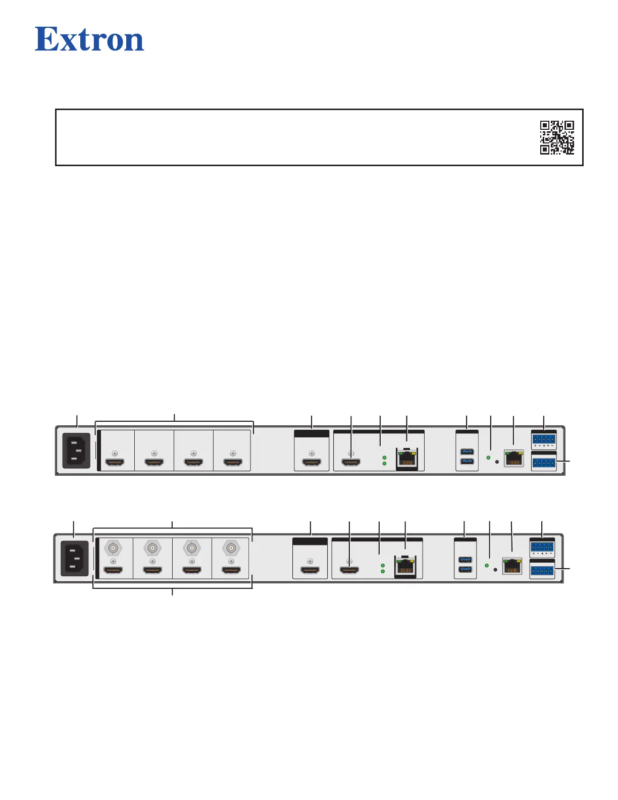
Rear Panel Features and Connections
100-240V
~
1.5A MAX
50-60Hz
MGP 641 xi
INPUTS
1
HDMI
4
HDMI
1A
HDMI
HDMI
3
HDMI
2
HDMI
BACKGROUND
INPUT
OUTPUTS (DTP3/XTP/HDBT) AUDIO OUT
REMOTE
OUT
SIG LINK
1B
DTP3
DTP
DTP
POWER
900mA
DEVICES
1
2
LAN
RESET
LR
Tx Rx G
RS-232
A
A
B
B
C
C
D
D
E
E
F
F
G
G
I
I
J
J
H
H
100-240V
~
1.5A MAX
50-60Hz
INPUTS
HDMI HDMI
1A
HDMI
HDMIHDMIHDMI
BACKGROUND
INPUT
OUTPUTS (DTP3/XTP/HDBT) AUDIO OUT
REMOTE
OUT
SIG LINK
1B
DTP3
DTP
DTP
POWER
900mA
DEVICES
1
2
LAN
RESET
LR
Tx Rx G
RS-232
1 SDI 2 SDI 3 SDI 4 SDI
MGP 641 xi SDI
A
A
L
L
C
C
D
D
E
E
F
F
G
G
I
I
J
J
H
H
B
B
A
AC power connector
E
DTP remote power LEDs
I
Ethernet LAN connector
B
HDMI inputs
F
DTP/XTP/HDBT output (output 1B)
J
ANALOG AUDIO OUT connector
C
HDMI live BACKGROUND INPUT
G
USB device connectors
K
REMOTE RS-232 connector
D
HDMI output (output 1A)
H
RESET button and LED
L
SDI inputs
Figure 1. Rear Panels
1
1