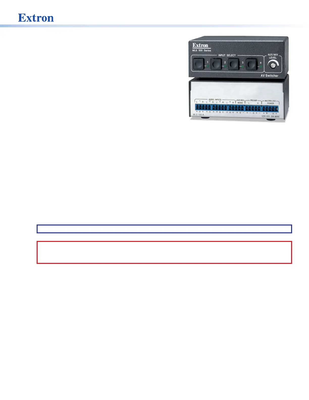
2
MLS 100 A • User Guide (Continued)
Rear Panel Features and Cabling
Turn off and disconnect power from all the equipment before you connect cables to the
MLS.
Audio Connections
1
Audio Inputs — Each of these 3-pole, 3.5 mm captive screw connectors accepts one unbalanced stereo or mono audio
input. Wire each captive screw connector as shown in figure 1, depending on the input type.
Connect two RCA-style (tip-ring) connectors to the other end of each audio input cable as shown in gure 2.
LR
Audio Input Wiring
(unbalanced, stereo)
Aux/Mix Input Wiring
(balanced/unbalanced, mono)
AUX
/
MIX
MONO
LR
Audio Input Wiring
Left (+)
Right (+)
Gnd (Sleeve, )
Left (+)
eve, )
Tip (+)
Ring (–)
Gnd (Sleeve, )
Sleeve (Gnd)
Figure 1. Captive Screw Connector Figure 2. RCA-style Connectors
2
Aux/Mix Mono audio input —The Aux/Mix Mono audio channel is always active: its signal
is output no matter which, if any, other audio input (input 1, 2, 3, or 4) is selected. For
example, you could connect the output of a wireless microphone receiver to this port so the
presenter comments can always be heard and are independent of the A/V source used for
the presentation.
The mix output level can be adjusted between ‑43dB and +24dB.
LR
Audio Input Wiring
(unbalanced, stereo)
Aux/Mix Input Wiring
(balanced/unbalanced, mono)
AUX
/
MIX
MONO
LR
Audio Input Wiring
(unbalanced, mono)
Left (+)
Right (+)
Gnd (Sleeve, )
Left (+)
Gnd (Sleeve, )
Tip (+)
Ring (–)
Gnd (Sleeve, )
NOTE: The Aux/Mix level must be adjusted physically via the front panel control. It cannot be
adjusted via software.
Connect a 3.5 mm, 3-pole captive screw connector to one end of an audio cable as shown at right.
3
Audio output (Preamp) — Connect self-powered speakers or another stereo audio device to
the MLS via this 5-pole, 3.5 mm captive screw connector. Depending on how the connector is
wired, the audio output can be balanced or unbalanced stereo audio. Wire the connector as
shown in figure 3.
Audio Output Captive Screw_MLS 100.eps
Unbalanced Output
Tip
See Caution
Sleeve (s)
Tip
See Caution
Balanced Output
Tip
Ring
Sleeve (s)
Tip
Ring
LR
OUT
OUT
LR
Figure 3. Wiring the Connector
ATTENTION: For unbalanced audio, connect the sleeves to the ground contact. DO NOT connect the sleeves to the
negative (–) contacts.
ATTENTION : Pour l’audio asymétrique, connectez les manchons au contact au sol. Ne PAS connecter les manchons
aux contacts négatifs (–).
After all the equipment has been cabled and powered on, use the MediaLink Control Program or an RS-232 controller to
set the per-input gain/attenuation to match the correct audio output level for the kind of output (balanced or unbalanced)
you need. See Setting Up Optimal Audio Gain on page3 and Switcher (MLS) Config on page13 for details on
determining and setting the gain/attenuation to produce the desired output levels.
NOTES:
• If you wire an audio output for balanced output, the MLS outputs a unity signal (input level = output level). Wiring an
audio output for unbalanced output causes the audio signal to be attenuated by 6dB.
• Overall volume control ranges from 0% (90 dB attenuation) to 100% (0dB attenuation). Adjustment increments are
1dB for steps from 1% to 40% volume. Adjustments are in 0.5 dB increments from 41% to 100% of full volume.
MLS 100 A
LR
A
B
LR
LR
LR
1
2
3
LR
4
AUX/MIX
MONO
AUDIO INPUTS
MLC/RS-232
POWER
12V .5A MAX
PREAMP
11223
34
4
1
2
3