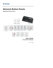
Extron PowerCage 411 Manual

Extron Ikke kategoriseret PowerCage 411

Læs gratis den danske manual til Extron PowerCage 411 (4 sider) i kategorien Ikke kategoriseret. Denne vejledning er vurderet som hjælpsom af 62 personer og har en gennemsnitlig bedømmelse på 4.2 stjerner ud af 31.5 anmeldelser. Har du et spørgsmål om Extron PowerCage 411, eller vil du spørge andre brugere om produktet?

Side 1/4
1
IMPORTANT:
I
I
I
IM
M
M
MP
P
P
PO
O
O
ORT
RT
RT
RTA
A
A
AN
N
N
NT:
T:
T:
T:
Go to www.extron.com for the complete
user guide, installation instructions, and
specifications before connecting the
product to the power source.
PowerCage 411 Enclosure • Setup Guide
This setup guide contains installation information for the PowerCage411FOX3 Enclosure using step-by-step instructions. For
complete instructions, see the at PowerCage411Series User Guide www.extron.com.
WARNING: . Potential risk of severe injury Installation and service must be performed by authorized personnel only.
AVERTISSEMENT : L’installation et l’entretien doivent être effectués Risque potentiel de blessure grave ou de mort.
par le personnel autorisé uniquement.
Rear Panel Features
B
B
B
B
B
BA
A
A
A
A
A
RS-232
LAN
Rx GT x
REMOTE
100 -240V ~ A -- MAX 10 0-24 0V ~ A X-- MA
50 -6 50 -60 Hz 0 Hz
FOX3 T 301 PC
C
RS-232
Rx G
Tx
AUDIO IN
HDMI INPUT OOP OUL T
OUT IN OUT IN
USB HID USB 2.0
N
OUT I
U
T
A B
FOX3 T 301 PC
C
RS-232
Rx GTx
AUDIO IN
HDMI INPUT OOP OUL T
OUT IN OUT IN
USB HID USB 2.0
N
OUT I
UT
A B
FOX3 T 301 PC
RS-232
Rx GTx
AUDIO IN
HDMI INPUT LOOP OUT
OUT IN OUT IN
USB HID USB 2.0
OUT I
UT
A B
FOX3 T 301 PC
C
RS-232
Rx GTx
AUDIO IN
HDMI INPUT OOP OUL T
OUT IN OUT IN
USB HID USB 2.0
OUT I
UT
A B
C
C
C
C
C
C D
D
D
D
D
D
Figure 1. PowerCage 411 Rear Panel
A — Connect these ports to 110-240 VAC, 50-60 Hz power sources using standard IEC power Power connectors 1 and 2
cords.
B — Install a PowerCage 411- compatible board into each slot.Slot 1 through Slot 4
C — Use an RJ-45 cable to connect to a LAN (Ethernet) for control of the device.LAN port
Use a straight-through cable for connection to a switch, hub, or router.
Use a crossover or a straight-through cable for connection directly to a PC.
D — To control the unit, connect an RS-232 device to the 3-pole, 3.5 mm captive screw port and Remote RS-232 port
configure it as follows: 9600 baud rate, 8 data bits, 1 stop bit, no parity.
Installing Boards into the Enclosure
Any combination of up to four boards can be installed in the PowerCage enclosure. The quantity and type of boards vary
depending on the conguration for each installation site.
Before installing the boards in the enclosure, refer to the model-specic guide for each PowerCage board being installed. The
guides describe the features of each board and how to set up and cable it.
NOTE: The power supplies and boards are hot-swappable; they can be installed or removed without turning off or
disconnecting the power to the PowerCage411FOX3 Enclosure.
CAUTION:
Use ESD precautions when installing a board to avoid damaging it. Keep the board in the anti-static bag until it is
needed.
Prenez les précautions ESD lorsque vous installez une carte afin d’éviter de l’endommager. Gardez la carte dans le
sachet dépoussiérant jusqu’à ce que vous en ayez besoin.
Use proper grounding techniques during installation.
Utilisez des techniques de mise à la terre correctes pendant l’installation.
2
PowerCage 411 Enclosure • Setup Guide (Continued)
1. Where applicable, remove as many blank plates
or previously installed boards from the rear of the
PowerCage Enclosure as necessary to accommodate the
number of new boards to be installed.
2. Carefully slide the board into the slot, aligning the bottom
edge of the board with the left and right board mounting
slides on the bottom of the enclosure slot. Push the board
completely into the slot and finger-tighten the two top
screws while pushing in the screws to secure the board in
place (see figure2).
3. Repeat for all boards needing installation.step 2
NOTE: Cover all empty board slots; do not leave them
open. Securely fasten the screws for all boards and
blank panels.
FOX3 T 301 PC
RS- 232
x G
Tx
AUD N
HDMI INPUT LOOP OUT
OUT IN O UT IN
USB HID USB 2.0
A
B
RS-232
L
Rx GTx
REMOT E
FOX3 T 301 PC
RS- 232
RxG
Tx
AUD N
HDMI INPU T LOOP OUT
OUT IN OUT I N
USB HID USB 2.0
A
B
FOX3 T 301 PC
RS-232
RxG
Tx
AUD N
HDMI INPU T LOOP OUT
OUT IN OUT IN
USB HID USB 2.0
A
B
FOX3 T 301 PC
-232
RxG
HDMI INPU T LOOP OUT
OUT IN OUT I N
SB 2.0
A
B
Screws
(2 per board)
Align board and
slide into slot.
Figure 2. Board Installation
Front Panel Features
ADJUST
MENU
NEXT
RESET
POWERCAGE 411
215W
POWER SUPPLY
215W
POWER SUPPLY
CONFIG
E
A
A
A
A
A
A
D
D
D
D
D
D
C
C
C
C
C
C C
C
C
C
C
CA
A
A
A
A
A C
C
C
C
C
C C
C
C
C
C
C
G
G
G
G
G
G H
H
H
H
H
HF
F
F
F
F
FB
B
B
B
B
B
B
B
B
B
B
B
B
B
B
B B
B
B
B
B
BE
E
E
E
E
E
Figure 3. PowerCage 411 FOX3 Front Panel
A Power supply LEDs
LED Color - State Power Supply Status Fan Status
Green - Solid Good Both fans functional
Red - Solid Failed Both fans functional
Orange - Solid No AC power present Both fans functional
Green - Blinking Good Either fan not functional
Red - Blinking Failed Either fan not functional
Orange - Blinking No AC power present Either fan not functional
B — Connect power to IEC power connector 1 or 2 (see , Power supplies figure1 A on page1).
C — For power supplies.Fans
D — If desired, connect a host device to the front panel USB mini-B port for configuring the enclosure.Configuration port
NOTE: This port allows communication to the enclosure and the boards.
E — The screen displays messages, menu information, and your selections (see LCD screen Menus, Configuration, and
Adjustments on page3).
F — Pressing the button sets various enclosure settings to the factory default values. The LED Reset button and LED Reset
lights green after pressing the button (see the for details).Reset PowerCage 411 Series User Guide
G Navigation buttons
MENU — Press to access the PowerCage 411 menu system (see MENU Menus, Configuration, and Adjustments).
NEXT — From each menu press to step through submenus (see ). NEXT Menus, Configuration, and Adjustments
H Navigation adjust knobs
Horizontal — Turn the horizontal adjust knob to navigate the menu system (see Menus, Configuration, and
Adjustments).
Vertical — Turn the vertical adjust knob to navigate the menu system (see ).Menus, Configuration, and Adjustments


Produkt Specifikationer

Mærke: Extron
Kategori: Ikke kategoriseret
Model: PowerCage 411

Har du brug for hjælp?

Hvis du har brug for hjælp til Extron PowerCage 411 stil et spørgsmål nedenfor, og andre brugere vil svare dig


Ikke kategoriseret Extron Manualer

Ikke kategoriseret Manualer

Nyeste Ikke kategoriseret Manualer