Hinweis, Note, Information. . . . . . . . . . . . . . . . . . . . . . . . . .
de Einbau und Inbetriebnahme nur von qualifiziertem
Fachpersonal, gemäß Bedienungsanleitung.
en Fitting and commissioning to be carried out by
qualified personnel only in accordance with the
sv Montering och idrifttagning får endast utföras av
auktoriserad fackkunnig personal i enlighet med
Only for use in Class 2 Circuits
This device is intended to be used with a Class 2 power
source or Class 2 transformer in accordance with UL1310 or
As an alternative a LV/C (Limited Voltage/Current) power
source with one of the following properties can be used:
– This device shall be used with a suitable isolating source
such that the maximum open circuit voltage potential
available to the product is not more than 24 V DC and the
current is limited to a value not exceeding 8 amperes
measured after 1 minute of operation.
– This device shall be used with a suitable isolating source
in conjunction with a fuse in accordance with UL248. The
fuse shall be rated max. 4 A and be installed in the
24 V DC power supply to the device in order to limit the
In determining the acceptability of the combination, the
following detail should be examined:
– These devices are intended and investigated for use with
CP String from Festo Programmable controllers only.
CPI-Modul CP-A08-M12-EL-Z (8A) de. . . . . . . . . . . . . . . . . . . . . . . . .
Das CPI-Modul CP-A08-M12-EL-Z ist ausschließlich bestimmt
für den Einsatz an einem CP-Strang von Festo. CPI-/CP-
Module sind nur folgendermaßen zu benutzen:
– im Originalzustand, ohne eigenmächtige Veränderungen
– in technisch einwandfreiem Zustand
Das CPI-Modul CP-A08-M12-EL-Z unterstützt CPI-Systeme mit
erweiterter Funktionalität.
Es sind die angegebenen Grenzwerte für Temperaturen, elek-
trische Daten, Drehmomente usw. einzuhalten. Ausführliche
Informationen finden Sie in der Beschreibung
Typ P.BE-CPEA-CL-... (Kombinierte Beschreibung für CP-CL und
3 Einbau und Inbetriebnahme
Hinweis..................................................
Schalten Sie vor Installations- und Wartungsarbeiten
– Betriebs- und Lastspannungsversorgung.
– Befestigung des Moduls: Mit integrierter Hutschienenbefe-
stigung (mit beigefügtem Befestigungs-Set) oder Wand-
– Befestigung der Schilderträger 7: An integrierten Auf-
stecknuten an Längs- und Schmalseite. Schilderträger aJ
können Sie über die Teilenummer 547473 (Typ ASCF-H-E2)
Wenn Sie in einem CP-Strang ein CPI-Modul einsetzen wollen,
• Lastversorgung Ausgänge anschließen
• Spannungsversorgung am CPI-Master einschalten.
• Automatische Erkennung der Strangbelegung am CPI-
Master mit SAVE-Taste oder DIL-Schalter durchführen.
Beachten Sie die Anwenderdokumentation des Masters.
• CPI-Master neu starten (Power OFF/ON).
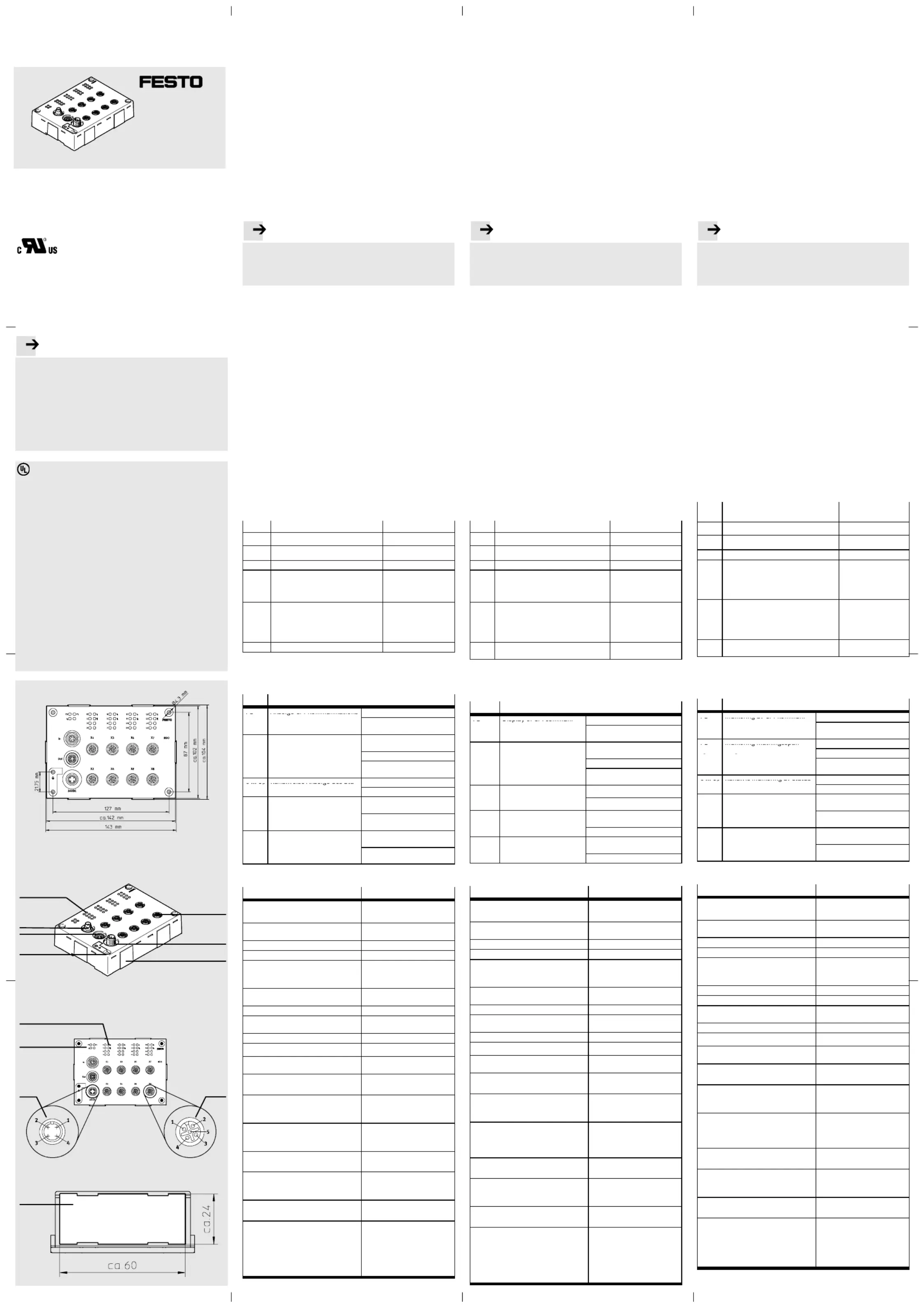
Bild 1 zeigt die Modulmaße. Die Höhe des Moduls beträgt
Bild 2 zeigt die Anschlüsse des Moduls CP-A08-M12-EL-Z:
1CPI In (M9, Buchse, 5 polig) -
2CPI Out (M9, Stecker, 5 polig) -
4Externe Lastversorgung (1x M12,
5Aktor (8x M12, Buchse, 5 polig) Pin 1: n.c.
* Pin 2:nur belegt bei x1, x3, x5, x7
4 Diagnose über LEDs 6
6
6
66
Das CPI-Modul CP-A08-M12-EL-Z verfügt über eine kanal-
weise Kurzschluss/Überlast Überwachung der Ausgänge.
LED Betriebszustand und Fehleranzeige
Anzeige CPI-Kommunikations
leuchtet: Kommunikation OK
Status (Betriebsspannungs-
aus: Betriebsspannung liegt
leuchtet: Lastspannungsver-
aus: Lastspannungsversor-
Kanalweise Anzeige des Sta-
Modulweise Anzeige (1x) von
leuchtet: Kurzschluss/Über-
aus: kein Kurzschluss/Über-
Kanalweise Anzeige (8x) von
leuchtet: Kurzschluss/Über-
aus: kein Kurzschluss/Über-
Digitale Ausgänge 8 Ausgänge nach IEC 61131
Ausgangsverzögerungszeit bei
Ausgangsstrom pro Kanal max. 0,5 A
Spannungsabfall über Ausgang < 1V
Logik-Stromaufnahme über CPI-
Parallelschaltung von Ausgängen max. 2
Externe Lastversorgung +24VDC +/-25%
Ansprechschwelle ≥1A, träge
Autom. Spannungswiederkehr nach
Schutzart (Steckverbinder gesteckt
oder mit Schutzkappe versehen)
Schutz gegen elektrischen Schlag
(direktes und indirektes Berühren
Elektromagnetische Verträglichkeit
siehe Konformitätserklärung
Schwingung und Schock geprüft nach IEC / EN 60068
Zulässige Umgebungstemperatur
Relative Luftfeuchtigkeit 95 % bei 40 °C,
festigungsset beiliegend)
über Erdungsanschlussblech
CPI module CP-A08-M12-EL-Z (8O) en. . . . . . . . . . . . . . . . . . . . . . . .
CPI module CP-A08-M12-EL-Z is intended exclusively for use
on a CP string from Festo. CPI/CP modules may only be used
– without any modifications by the user.
– in faultless technical condition
CPI module CP-A08-M12-EL-Z supports CPI systems with
The maximum values specified for temperatures, electrical
data, torques etc. must be observed. Detailed information
can be found in the manual
type P.BE-CPEA-CL-... (combined manual for CP-CL and CP-EL
3 Installation and commissioning
Note......................................................
Before carrying out installation and maintenance work,
switch off the following:
– the compressed air supply
– the operating and load voltage supplies.
– Fastening the module With integrated hat rail fastening
(with fastening set supplied) or wall fitting.
– Fastening the inscription plate 7: Onto integrated
clip-in grooves on the long and narrow sides. Inscription
plates aJ can be ordered under part number 547473
If you wish to insert a CPI module in a CP string proceed as
• Connect the load supply for the outputs.
• Switch on the power supply on the CPI master.
• Carry out automatic recogniton of the string assignment
on the CPI master with the SAVE button or with the DIL
switch. Observe the instructions in the user documenta-
• Start the CPI master again (Power OFF/ON).
Fig. 1 shows the module dimensions. The module is
Fig. 2 shows the connections of module CP-A08-M12-EL-Z.
Connection Pin assignment
1CPI In (M9, socket, 5-pin) -
2CPI Out (M9, plug, 5-pin) -
4External load supply (1x M12, plug,
5Actuator (8x M12, socket, 5-pin) Pin 1: n.c.
* Pin 2: assigned only with x1, x3,
4 Diagnosis via LEDs 6
6
6
66
CPI module CP-A08-M12-EL-Z has channel-by-channel moni-
toring of short circut/overload of the outputs.
LED Operating status and fault display
lights up: Communication OK
out: Operating voltage not
Display of status of load
out: No short circuit/overload
P(red) Channel-by-channel
out: No short circuit/overload
5 Technical specifications
Digital outputs 8 outputs as per IEC 61131
Output current per channel max. 0.5 A
Voltage drop at output < 1 V
Logic current consumption via CPI
Parallel switching of outputs max. 2
External load supply +24 V DC +/-25%
Response threshold ≥1A, slow-blowing
Automatic Voltage return after short
Protection type (plug connector
inserted or with protective cap)
Protection against electric shock
(direct and indirect contact as per
by means of a PELV circuit
Electromagnetic compatibility
– EMC interference emission
– EMC resistance to interference
Vibration and shock tested as per IEC / EN 60068
Permitted ambient temperature
Relative air humidity 95 % at 40 °C,
with hat rail fastening by
means of terminal (fastening
CPI-modulen CP-A08-M12-EL-Z sv. . . . . . . . . . . . . . . . . . . . . . . . . . . .
CPI-modulen CP-A08-M12-EL-Z är endast avsedd för använd-
ning på en CP-sträng från Festo. CPI-/CP-moduler ska endast
– enligt gällande bestämmelser
– i originalskick utan egna förändringar
– i tekniskt felfritt skick.
CPI-modulen CP-A08-M12-EL-Z stödjer CPI-system med utö-
Angivna gränsvärden för temperatur, elektrisk data, vridmo-
ment etc. ska beaktas. Utförlig information finns i manualen
typ P.BE-CPEA-CL-... (kombinerad beskrivning för CP-CL- och
3 Montering och idrifttagning
Information.............................................
Innan installations- och underhållsarbeten påbörjas ska
– Matnings- och lastspänningsförsörjning
– Fastsättning av modulen: Med integrerat reläskenfäste
(med bifogat monteringsset) eller väggmontage.
– Skylthållarfäste 7: På integrerade insticksspår på längssi-
dan och smalsidan. Skylthållare aJ kan beställas med arti-
kelnummer 547473 (typ ASCF-H-E2).
Gör så här om du vill sätta in en CPI-modul i en CP-sträng:
• Anslut Matningsförsörjning utgångar.
• Koppla till spänningsförsörjningen till CPI-mastern.
• Utför automatisk registrering av strängschemat på CPI-
mastern med knappen SAVE eller DIL-omkopplare. Följ
• Starta om CPI-mastern (Power OFF/ON).
Bild 1 visar modulmåtten. Modulhöjden är ca 30 mm.
Bild 2 visar anslutningarna till modulen CP-A08-M12-EL-Z:
Anslutning Kontaktkonfigura-
1CPI In (M9, honkontakt, 5-polig) -
2CPI Out (M9, hankontakt, 5-polig) -
4Extern lastförsörjning (1x M12, han-
5Aktor (8x M12, honkontakt,5-polig) Stift 1: n.c.
* stift 2:används endast vid x1, x3,
4 Diagnos via lysdioder (LED) 6
6
6
66
CPI-modulen CP-A08-M12-EL-Z har kanalvis korstslut-
nings-/överlastövervakning av utgångarna.
LED Drifttillstånd och felindikering
Indikering av CPI-kommuni-
Lyser: Matningsspänning OK
Kanalvis indikering av status
Släckt: Ingen signalutgång
Modulvis indikering (1x) av
kortslutning/överbelastning
Lyser: Kortslutning/överbe-
Släckt: Ingen kortslutning/
Kanalvis indikering (8x) av
kortslutning/överbelastning
Lyser: Kortslutning/överbe-
Släckt: Ingen kortslutning/
Digitala utgångar 8 utgångar enligt IEC 61131
Utgångsfördröjningstid vid
Utgångsström per kanal max. 0,5 A
Spänningsfall vid utgång < 1V
Logikströmförbrukning via CPI-system max. 35 mA vid 24 V
Parallellkoppling av utgångar max. 2
Extern matningsspänning +24 VDC +/-25 %
Aktiveringsgräns ≥1A, trög
Autom. spänningsåterställning efter
Kapslingsklass (instickskontakten in-
kopplad eller har skyddsplugg)
Skydd mot elektriska stötar (direkt
och indirekt beröring enligt IEC/DIN
Elektromagnetisk kompatibilitet
Vibrationer och stötar kontrollerad enligt IEC /
EN 60068, del 2-6 och 2-27
Tillåten omgivningstemperatur
Relativ luftfuktighet 95 % vid 40 °C,
via jordbleck med jordkabel


