Festo VABD-S2-1-S-C Manual

Festo Ikke kategoriseret VABD-S2-1-S-C

Læs gratis den danske manual til Festo VABD-S2-1-S-C (2 sider) i kategorien Ikke kategoriseret. Denne vejledning er vurderet som hjælpsom af 2 personer og har en gennemsnitlig bedømmelse på 4.7 stjerner ud af 1.5 anmeldelser. Har du et spørgsmål om Festo VABD-S2-1-S-C, eller vil du spørge andre brugere om produktet?

Side 1/2
Montageanleitung (de)
752 133 / 2010-06NH
†‡
Dichtung/Verschlusskappe
VABD-S2-1-S-C/VABD-S4-E-C
Festo SE & Co. KG
Postfach
D-73726 Esslingen
++49/(0)711/347-0
www.festo.com
Warnung
Vor elektrischem Schlag und unkontrollierten Bewegungen von Bauteilen!
Verletzungen können die Folge sein.
Stellen Sie sicher, dass im strom- und drucklosen Zustand montiert bzw.
demontiert wird.
Info
Beachten Sie die Anwenderdokumentation aller Bauteile.
Halten Sie die zulässigen Anziehdrehmomente ein.
1)
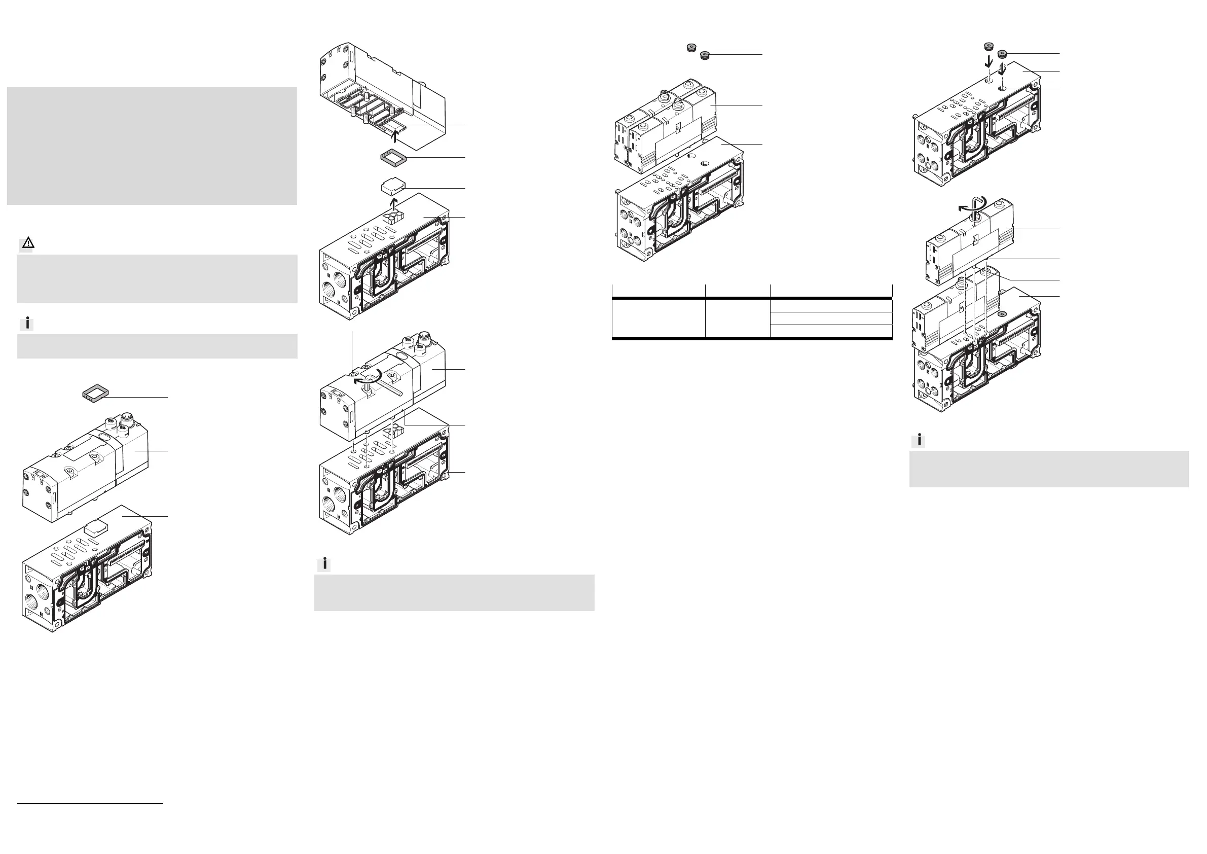
1. Teileliste VABD-S2-1-S-C
14764d_1
1 Dichtung (1x)
VABD-S2-1-S-C
14764d_2
Nicht im Lieferumfang:
2 Magnetventil (1x)
VSVA-B-…-D…-1R5L
3 Verkettungsplatte (1x)
VABV-S2-1S/-2S-…
Bestimmungsgemäß dient die Dichtung 1 dazu,
dass bei de
r Montage von
Ventil 2, die Ventilinsel die Schutzart IP65 weiterhin erfüllt.
1)
Toleranzen für nicht tolerierte Anziehdrehmomente M
A
M
A
≤ 2,Nm: ± 10%
M
A
≥ 3 Nm: ± 20%
1a. Montage Dichtung 1
14764d_4
Drücken Sie die Dichtung 1
in die Nut am Ventil 2.
14764d_3
Entfernen Sie die Schutz-
kappe (A) von der Verket-
tungsplatte 3.
14764d_5
Befestigen Sie das Ventil 2
inklusive Dichtung 1 auf der
Verkettungsplatte 3 mit den
Schrauben (A). Halten Sie die
zulässigen Anzieh-
drehmomente ein.
VSVA-B-…
D1: 3 Nm
D2: 6,5 Nm
Info
Baugrößen der Magnetventile:
D1 = 42 mm = Größe ISO 1
D2 = 52 mm = Größe ISO 2
2. Teileliste VABD-S4-E-C
14764d_6
1 Verschlusskappe (2x)
VABD-S4-E-C
14764d_7
Nicht im Lieferumfang:
2 Magnetventil (2x)
Tabelle
3 Verkettungsplatte (1x)
VABV-S4-1/-2…
Magnetventil 2
Baugröße Elektrischer Anschluss
VSVA-B-… -A1/-A2-… -1R2L
-1R5L
-…C1
Bestimmu
ngsgem
äß d
ient die Verschlusskappe 1 dazu, dass bei der Mon-
tage von Ventil 2, die Ventilinsel die Schutzart IP65 weiterhin erfüllt.
2a. Montage Verschlusskappe 1
14764d_8
Drücken Sie die Verschluss-
kappe 1 in die Boh-
rungen (A) der Verkettungs-
platte 3.
14764d_9
Achten Sie auf den einge-
pressten Codierstift (B), um
das Ventil lageorientiert zu
montieren.
Befestigen Sie die Ventile 2
auf der Verkettungsplatte 3
mit den Schrauben (A). Hal-
ten Sie die zulässigen
Anziehdrehmomente ein.
VSVA-B-…
A1: 2 Nm
A2: 1 Nm
Info
Baugrößen der Magnetventile:
A1 = 26 mm = Größe 01
A2 = 18 mm = Größe 02
1
3
2
1
A
3
1
2
3
1
2
3
3
2
B
A
A
3
2
1
A
Assembly instructions (en)
752 133 / 2010-06NH
†‡
Seal/Sealing cap
VABD-S2-1-S-C/VABD-S4-E-C
Festo SE & Co. KG
Postfach
D-73726 Esslingen
++49/(0)711/347-0
www.festo.com
Warning
Beware of electric shock and uncontrolled movements of components!
They can cause injury.
Make sure that mounting or removal is performed in the de-energised
and pressureless state.
Information
Observe the user documentation for all components.
Observe the permitted tightening torques.
1)
1. Parts lis
t VABD-S2-1-S-C
14764d_1
1 Seal (1x)
VABD-S2-1-S-C
14764d_2
Not included in scope of
delivery:
2 Solenoid valve (1x)
VSVA-B-…-D…-1R5L
3 Manifold sub-base (1x)
VABV-S2-1S/-2S-…
The seal 1 is i
nten
ded to ensure that the valve terminal continues to fulfil
protection class IP65 when the valve 2 is mounted.
1)
Tolerance for non-toleranced tightening torques M
A
M
A
≤ 2,Nm: ± 10%
M
A
≥ 3 Nm: ± 20%
1a. Fitting the seals 1
14764d_4
Press the seal 1 into the
groove at the valve 2.
14764d_3
Remove the dust cap (A)
from the manifold sub-
base 3.
14764d_5
Fasten the valve 2,
including seal 1, with the
screws (A) to the manifold
sub-base 3. Observe the
permitted tightening
torques.
VSVA-B-…
D1: 3 Nm
D2: 6.5 Nm
Information
Sizes of the solenoid valves:
D1 = 42 mm = Size ISO 1
D2 = 52 mm = Size ISO 2
2. Parts list VABD-S4-E-C
14764d_6
1 Sealing cap (2x)
VABD-S4-E-C
14764d_7
Not included in scope of
delivery:
2 Solenoid valve (2x)
Table
3 Manifold sub-base (1x)
VABV-S4-1/-2…
Solenoid valve 2
Size Electrical connection
VSVA-B-… -A1/-A2-… -1R2L
-1R5L
-…C1
The sealin
g cap
1 is intended to ensure that the valve terminal continues to
fulfil protection class IP65 when the valve 2 is mounted.
2a. Mounting of sealing cap 1
14764d_8
Press the sealing cap 1 into
the holes (A) of the manifold
sub-base 3.
14764d_9
Note the pressed-in coding
pin (B) in order to mount the
valve in the correct position.
Fasten the valve 2 with the
screws (A) to the manifold
sub-base 3. Observe the
permitted tightening
torques.
VSVA-B-…
A1: 2 Nm
A2: 1 Nm
Information
Sizes of the solenoid valves:
A1 = 26 mm = Size 01
A2 = 18 mm = Size 02
1
3
2
1
A
3
1
2
3
1
2
3
3
2
B
A
A
3
2
1
A


Produkt Specifikationer

Mærke: Festo
Kategori: Ikke kategoriseret
Model: VABD-S2-1-S-C

Har du brug for hjælp?

Hvis du har brug for hjælp til Festo VABD-S2-1-S-C stil et spørgsmål nedenfor, og andre brugere vil svare dig