Änderungen vorbehalten / All rights for alterations reserved / Sous réserve de modications
Festo SE & Co. KG, Postfach D-73726 Esslingen, Phone: +49/711/347-0
Montage- und Bedienungsanleitung / Mounting and operating instructions Instructions de service et de montage/
- Für Lichtleiter ø2,2 mm
- DIN Schienen-Montage (DIN-46277-3)
- Steuerleitung zur Einstellung oder
- Variante mit zusätzlichem Analogausgang
- Forbreopticsø2.2mm
- DIN rail mounting (DIN-46277-3)
- External teach for setting and to disable the teach button
- Type with additional analogue output
- Pourbresopt.ø2,2mm
- Montage sur rail DIN (DIN-46277-3)
- Verrouillageetapprentissagedéportésélectriquement
- Modèlepoursortieanalogiquesupplémentaire.
Umgebungstemperaturbereich: -20 ... +60 °C
Lagertemperaturbereich: -20 ... +80 °C
Anschlusskabel: 5 x 0,14 mm
Leitungslänge Standard: 2 m
Steckeranschluss: M 8x1; 4-polig
Anzugsdrehmoment Stecker: 0,6 Nm
Gewicht (Stecker): ca. 17 g
Gewicht (Kabel): ca. 58 g
Protection standard: IP64
Ambient temperature range: -20 ... +60 °C
Storage temperature range: -20 ... +80 °C
Standard cable length: 2 m
Tightening torque connector: 0.6 Nm
Weight (plug): approx. 17 g
Weight (cable): approx. 58 g
Caract.mécaniques(typ.)
Degré de protection: IP64
Température de fonctionnement: -20 ... +60 °C
Plage de température de stockage: -20 ... +80 °C
Câble de raccordement: 5 x 0,14 mm
Longueur de câble standard: 2 m
Connecteur de raccordement: M 8x1; 4 pôles
Couple de serrage connecteur: 0,6 Nm
Poids (Connecteur): env. 17 g
Amplicateurpourbresoptiques
Betriebsspannungsanschlüsse
= Teach-in Taste verriegelt
Stromaufnahme im Leerlauf: ≤ 25 mA bei 24 V DC
Schaltausgang: siehe Auswahltabelle
Ausgangsstrom Ie: ≤ 100 mA
Schaltfrequenz (ti/tp 1:1): abhängig von der Einstellung
Standard Mode 1000 Hz / Fast Mode 8000 Hz /
Fine Mode 125 Hz / High Distance Mode 125 Hz
Analogausgang nicht skalierbar: 0 - 10 V / 2 mA
Schaltausgangsanzeige: LED gelb
Betriebsspannungsanzeige: LED grün
Reverse battery protection U
: for all electr. operating
Power consumption (no load): ≤ 25 mA at 24 V DC
Signal output: see selection table
Output current Ie: ≤ 100 mA
Short-circuit protection: yes
Switching frequency (at ppp 1:1): depends on the setting
Standard Mode 1000 Hz / Fast Mode 8000 Hz /
Fine Mode 125 Hz / High Distance Mode 125 Hz
Analogue output not scalable: 0 - 10 V / 2 mA
Displayed value 0000: ≙ 0 V
Displayed value 4093: ≙ 10 V
Switching output indicator: LED yellow
Operating voltage indicator LED green:
Caract.électriques(typ.)
Protection contre les inversions de polarité U
raccordement électrique de tension
Apprentissage externe (ET): +U
= Bouton apprentissage teach-in verrouillé
Consommation en courant (sans charge): ≤ 25 mA à 24 V DC
Sorties de commutation: voir le tableau de choix
Courant de sortie Ie: ≤ 100 mA
Protection contre courts-circuits: oui
Fréquence de commutation (ti/tp 1:1): dépend du réglage
Standard Mode 1000 Hz / Fast Mode 8000 Hz /
Fine Mode 125 Hz / High Distance Mode 125 Hz
Sortie analogique non-réglable: 0 - 10 V / 2 mA
Afcheur sortie de commutation: LED jaune
Visualisation de la tension d'alimentation: LED verte
Reichweite: abhängig vom Lichtleiter
Standard Mode 100 % / Fast Mode ca. 40 % /
Fine Mode ca. 40 % / High Distance Mode ca. 190 %
Bezugsmaterial: Kodak weiß, 90 %, 200x200 mm
Lichtart: rot 630 nm, gepulst
Abstandshysterese (90 % / 90 %): < 10 % der eingestellten
Working range: depends on the bre
Standard Mode 100 % / Fast Mode approx. 40 % /
Fine Mode approx. 40 % / High Distance Mode approx. 190 %
Reference material: Kodak white, 90 %, 200x200 mm
Used light: red 630 nm, pulsed
Distance hysteresis (90 % / 90 %): < 10 % of adjusted
Distance de détection: dépend de la bre optique
Standard Mode 100 % / Fast Mode env. 40 % /
Fine Mode env. 40 % / High Distance Mode env. 190 %
Matériau de référence: Kodak blanc 90 %, 200x200 mm
Type de lumière: rouge 630 nm, pulsée
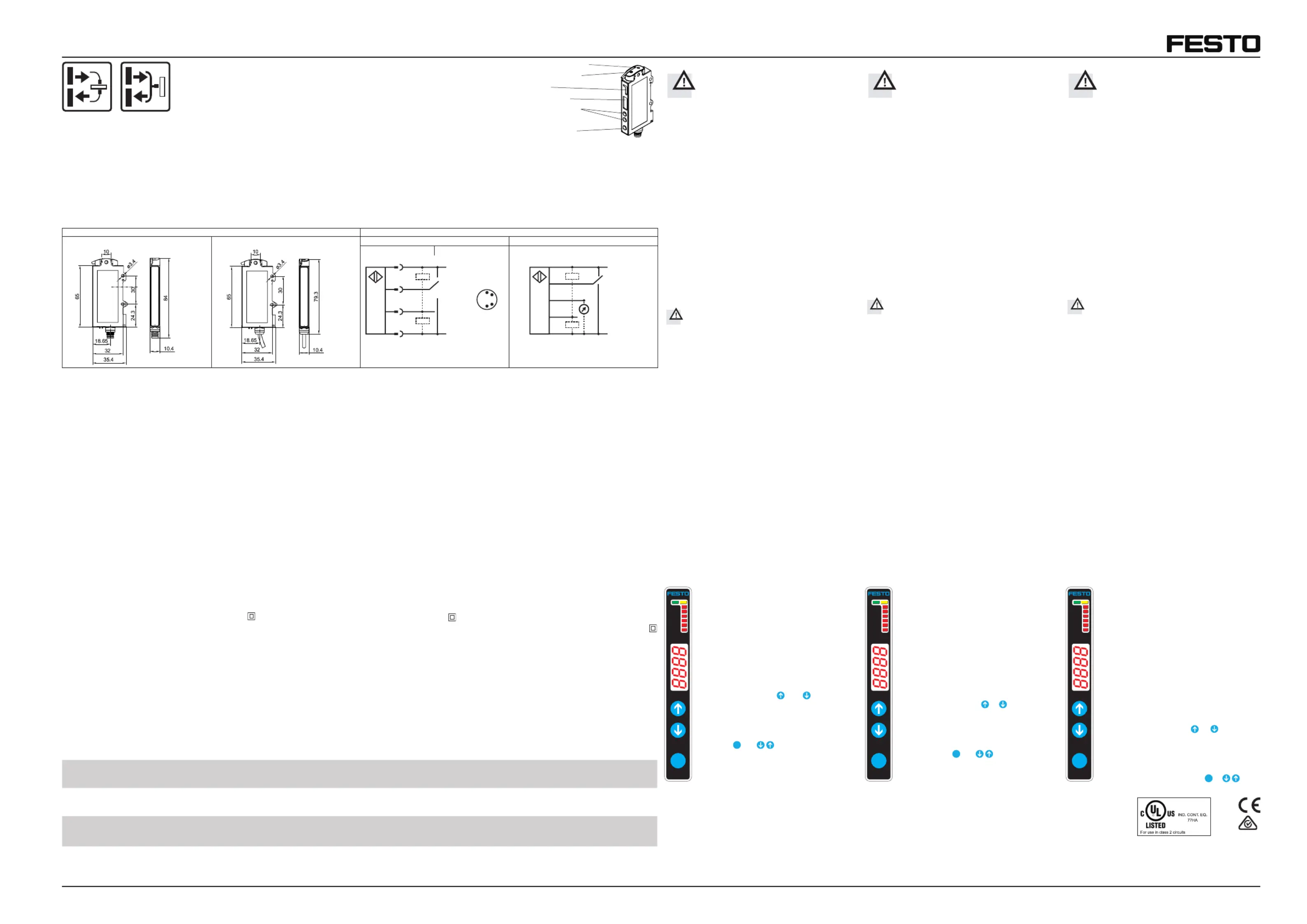
Maßzeichnung/Dimensionaldrawing/Plancoté Anschluss / Wiring / Raccordement
154-00476 155-00199 154-00191
Display / Display / Afcheur
S-Taste / S-Button / S-Touche
Empfänger / Receiver / Récepteur
Sender / Transmitter / Emetteur
Pfeil-Tasten / Up/down-Button /
Vor Inbetriebnahme des SOE4 diese
Betriebsanleitung, insbesondere die
Sicherheitshinweise, lesen, verstehen und
Der Anschluss des SOE4 darf nur durch Fachpersonal
Eingriffe und Veränderungen am Gerät sind nicht zulässig!
Die Sensorbaureihe SOE4 ist gemäß EU-Maschinenrichtlini-
en kein Sicherheitsbauteil und der Einsatz in Anwendungen,
bei denen die Sicherheit von Personen von Gerätefunktio-
nen abhängt, ist nicht zulässig.
It is essential that this manual is read, tho
roughly understood and observed before
setting the SOE4 into operation
The SOE4 may only be connected by qualied personnel.
Interventions and alterations to the device are not permis-
The SOE4 sensor line is no safety component as described
by EU machinery directives, and it is not authorized for
use in protecting human safety on machines and during
Avant la mise en marche du FL 70 R, lire,
comprendre et respecter impérativement
ce manuel d’instructions et plus
particulièrement ces consignes de sécurité.
Le raccordement du SOE4 ne doit être fait que par des
Des modications sur l’appareil ne sont pas permises !
Le SOE4 n’est pas une pièce de sécurité au sens des directi-
ves EU relatives aux machines et ne peut en aucun cas être
utilisé dans des applications où la sécurité des personnes
Einsatzzweck / Funktionsweise
Der SOE4 ist ein energetischer Sensor zur Verwendung von
Mit den entsprechenden LWL ist der Sensor als Taster oder
als Einweglichtschranke einsetzbar.
Der SOE4 darf nicht zum Sichern von Personen an Maschi-
nen und technischen Anwendungen eingesetzt werden.
Appropriate use / Functionality
The SOE4 is an energetic sensor for use with bre optics.
With the corresponding bre optics, the sensor may be used
as proximity switch or as through-beam sensor.
The SOE4 must not be used for the protection of persons
working on plants and machinery.
Le capteur optique, amplicateur, SOE4 s’utilise en combin-
aison avec des bres optiques plastiques.
Avec la bre correspondante, le capteur s’utilise en proxi-
Le SOE4 n’est pas destiné à garantir la sécurité des
personnes travaillant sur des machines et des applications
Le capteur est adapté pour être monté sur des rails DIN
(DIN-46277-3). Pour la xation par vis, deux trous sont déjà
Utilisation exclusive de bres optiques à raccord
plastique. Le capteur risque d‘être endommagé
par l‘utilisation de bres optiques à raccord
métallique p.ex. chargement électrique.
The sensor is suited for mounting on a DIN rail
For a mounting with screws there are two xing holes.
Only ber optics with plastic connections or plastic
Using metal connections may destroy the sensor
e.g. by electrostatic charge.
Der Sensor ist geeignet zur Montage auf einer DIN-Schiene
Zur Befestigung mit Schrauben sind zwei Bohrungen
Es dürfen nur Lichtleiter mit Kunststoffanschlüssen
bzw. Kunststoffadapter verwendet werden.
Bei Verwendung von Metallanschlüssen kann
der Sensor zerstört werden, z.B. durch statische
Montage de plusieurs appareils
On peut installer autant de capteurs que l’on souhaite les
uns à côté des autres. Une synchronisation automatique se
fait pour jusqu’à 4 capteurs, ce qui évite une interaction mu-
tuelle des appareils sur une même application. La synchro-
nisation se fait automatiquement en allumant le capteur.
En se basant sur un montage vertical avec connecteur, le
capteur placé le plus à gauche sera le "Master". Tous les au-
tres capteurs se comporteront en tant que "slave" et seront
en Stand-by si le " Master" est éteint. Cet état sera conservé
jusqu’à la prochaine mise sous tension ou coupure.
Mounting of several devices side by side
Any number of sensors may be mounted side by side.
Up to four sensors that are mounted side by side are
synchronized in order to avoid interaction in an application.
Synchronisation is effected automatically when operating
voltage is switched on. Based on a vertical mounting with
cable junction at the bottom, the left-most sensor is auto-
matically master. All other sensors act as slaves and switch
to stand-by mode when the master is switched off. Stand-by
is maintained until the sensor is switched off and on again.
Montage mehrerer Geräte nebeneinander
Es können beliebig viele Sensoren nebeneinander montiert
Maximal vier nebeneinander montierte Sensoren werden
synchronisiert, um eine gegenseitige Beeinussung an einer
Applikation zu vermeiden. Die Synchronisierung erfolgt
selbsttätig nach dem Einschalten der Betriebsspannung.
Ausgehend von senkrechter Montage mit Kabelanschluss
unten, wird der Sensor links außen automatisch zum
Master. Alle weiteren Sensoren agieren als Slave und gehen
in den Stand-by Zustand, falls der Master abgeschaltet wird.
Der Zustand wird bis zum nächsten Aus- und Wiederein-
Attachmentoftheplasticbreoptictothesensor
• Cut the bre to the desired length
(cutting tool available as accessory).
•Open the clamping bracket and insert the bre into the
bre holder as far as it will go.
Attention: The resistance caused by the O-ring has to be
• Close the clamping bracket.
Raccordementdelabreoptiqueplastiqueau
•Couper la bre à la longueur souhaitée (outil de coupage
disponible comme accessoire)
•Quand l’étrier est ouvert, pousser jusqu’au bout la bre
dans le support. Attention : ne pas tenir compte de la
résistance au niveau du joint.
Anschluss der Kunststoff-Faser am Sensor
• Die Faser auf die gewünschte Länge abschneiden
(Schneidewerkzeug ist als Zubehör erhältlich).
• Ist der Klemmbügel geöffnet, die Faser bis an den An-
schlag in den Faserhalter einführen.
Achtung: Widerstand beim Einführen am O-Ring muss
Der elektrische Anschluss erfolgt gemäß Anschlussbild des
entsprechenden Sensortyps.
The wiring is made according to the wiring diagram of the
corresponding sensor type.
La raccordement électrique s'effectue selon le schéma
correspondant au type de capteur.
LED gelb Schaltausgangsanzeige
LED grün Betriebsspannungsanzeige
LED rot CONF Konguration ist aktiv
LED rot LOCK Tastatursperre ist angewählt
LED rot NC Umschaltung des
LED rot ADJ Adjustfunktion ist angewählt
LED rot DELAY Zeitfunktion ist angewählt
LED rot FUNC Funktion ist angewählt
Das Display stellt die reektierte Energie in Form
eines Zahlenwertes als Ist-Wert (0-4095) dar.
eingestellte Schaltpunkt für 2 s angezeigt
(auch bei ausgeschaltetem Display möglich).
Der SOE4 hat verschiedene Funktionen, die mit
LED yellow Switching output indicator
LED green Operating voltage indicator
LED red CONF Conguration is active
LED red LOCK Keylock is selected
LED red NC Switching of signal output
LED red ADJ Adjust function is selected
LED red DELAY Time function is selected
LED red FUNC Function is selected
The display indicates the reected energy in
the form of a numerical value as actual value
ching point is displayed for 2 s
(also possible when display is switched off).
The SOE4 has various functions that may be set
LED jaune Afcheur sortie de commu-
LED verte Visualisation de la tension
LED rouge CONF Conguration activée
LED rouge LOCK Verrouillage touches est
LED rouge NC Inversion de la sortie de
LED rouge ADJ Fonction ajustement est
LED rouge DELAY Fonction temps est activée
LED rouge FUNC Fonction est activée
L’afchage représente l’énergie rééchie sous
forme d’une valeur chiffrée (0-4095).
En appuyant sur les touches
commutation réglé est afché pendant 2 s
(également possible quand afchage est éteint)
Le SOE4 dispose de plusieurs fonctions qui peu-
vent être réglées par les touches
Teile-Nr. / Typenbezeichnung 552799 552800 552801 552802
SOE4-FO-D-HF2-1P-M8 SOE4-FO-D-HF2-1N-M8 SOE4-FO-D-HF2-1PU-K SOE4-FO-D-HF2-1NU-K
Anschluss Stecker Stecker Kabel Kabel
Connection Connector Connector Cable Cable
Raccordement Connecteur Connecteur Câble Câble
Ausgang PNP NPN PNP N.O. analog NPN N.O. analog
Output N.O. N.O. PNP N.O. analogue NPN N.O. analogue
Sortie PNP N.O. analogique NPN N.O. analogique
For use in NFPA 79 Applications only.
Adapters providing eld wiring means
are available from the manufacturer.
Refer to manufacturers information.


