Fujitsu AOYG54KRTA Manual

Fujitsu Aircondition AOYG54KRTA

Læs gratis den danske manual til Fujitsu AOYG54KRTA (21 sider) i kategorien Aircondition. Denne vejledning er vurderet som hjælpsom af 46 personer og har en gennemsnitlig bedømmelse på 3.5 stjerner ud af 23.5 anmeldelser. Har du et spørgsmål om Fujitsu AOYG54KRTA, eller vil du spørge andre brugere om produktet?

Side 1/21
En-1
WARNING
• Installation of this product must be done by experienced service technicians or
professional installers only in accordance with this manual. Installation by nonprofes-
sional or improper installation of the product may cause serious accidents such as
injury, water leakage, electric shock, or re. If the product is installed in disregard of
the instructions in this manual, it will void the manufacturer’s warranty.
• To avoid getting an electric shock, never touch the electrical components soon
after the power supply has been turned off. After turning off the power, always wait
10 minutes or more before you touch the electrical components.
• Do not turn on the power until all work has been completed. Turning on the power be-
fore the work is completed can cause serious accidents such as electric shock or re.
• If refrigerant leaks while work is being carried out, ventilate the area. If the refrigerant
comes in contact with a ame, it produces a toxic gas.
• Installation must be performed in accordance with regulations, codes, or standards
for electrical wiring and equipment in each country, region, or the installation place.
• Do not use this equipment with air or any other unspeci ed refrigerant in the refriger-
ant lines. Excess pressure can cause a rupture.
• During installation, make sure that the refrigerant pipe is attached rmly before you
run the compressor.
Do not operate the compressor under the condition of refrigerant piping not attached
properly with 3-way valve open. This may cause abnormal pressure in the refrigera-
tion cycle that leads to rupture and even injury.
• When installing or relocating the air conditioner, do not mix gases other than the
speci ed refrigerant (R32) to enter the refrigerant cycle.
If air or other gas enters the refrigerant cycle, the pressure inside the cycle will rise to
an abnormally high value and cause rupture, injury, etc.
• To connect the indoor unit and outdoor unit, use air conditioner piping and cables
available locally as standard parts. This manual describes proper connections using
such installation set.
• Do not modify power cable, use extension cable or branch wiring. Improper use may
cause electric shock or re by poor connection, insuf cient insulation or over current.
• Do not purge the air with refrigerants but use a vacuum pump to vacuum the installation.
• There is not extra refrigerant in the outdoor unit for air purging.
• Use a vacuum pump for R32 or R410A exclusively.
• Using the same vacuum pump for different refrigerants may damage the vacuum
pump or the unit.
• Use a clean gauge manifold and charging hose for R32 or R410A exclusively.
• Do not use means to accelerate the defrosting process or to clean, other than those
recommended by the manufacturer.
• The appliance shall be stored in a room without continuously operating ignition sources
(for example: open ames, an operating gas appliance or an operating electric heater).
• Do not pierce or burn.
• Be aware that refrigerants may not contain an odour.
• During the pump-down operation, make sure that the compressor is turned off before
you remove the refrigerant piping.
Do not remove the connection pipe while the compressor is in operation with 3-way
valve open.
This may cause abnormal pressure in the refrigeration cycle that leads to rupture and
even injury.
• This appliance is not intended for use by persons (including children) with reduced
physical, sensory or mental capabilities, or lack of experience and knowledge, unless
they have been given supervision or instruction concerning use of the appliance by a
person responsible for their safety. Children should be supervised to ensure that they
do not play with the appliance.
CAUTION
• For the air conditioner to work appropriately, install it as written in this manual.
• This product must be installed by quali ed personnel with a capacity certi cation of
handling refrigerant uids. Refer to regulation and laws in use on installation place.
• Install the product by following local codes and regulations in force at the place of
installation, and the instructions provided by the manufacturer.
• This product is part of a set constituting an air conditioner. The product must not be
installed alone or be installed with non-authorized device by the manufacturer.
• Always use a separate power supply line protected by a circuit breaker operating on
all wires with a distance between contact of 3 mm for this product.
• To protect the persons, earth (ground) the product correctly, and use the power cable
combined with an Earth Leakage Circuit Breaker (ELCB).
• This product is not explosion proof, and therefore should not be installed in explosive
atmosphere.
• This product contains no user-serviceable parts. Always consult experienced service
technicians for repairing.
• When installing pipes shorter than 3 m, sound of the outdoor unit will be transferred
to the indoor unit, which will cause large operating sound or some abnormal sound.
• When moving or relocating the air conditioner, consult experienced service techni-
cians for disconnection and reinstallation of the product.
• Do not touch the ns of the heat exchanger. Touching the heat exchanger ns could
result in damage to the ns or personal injury such as skin rupture.
• An indoor unit error (error code: 2-3) occurs if an indoor unit for R410A is connected to
the refrigerant system in a concurrent multiple connection environment. In that case,
note the indoor model name that experiences the error, and contact our service centre.
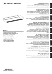
AIR CONDITIONER
OUTDOOR UNIT
INSTALLATION MANUAL
PART No. 9379069960
1. SAFETY PRECAUTIONS
• Be sure to read this manual thoroughly before installation.
• The warnings and precautions indicated in this manual contain important information
pertaining to your safety. Be sure to observe them.
• Hand this manual, together with the operating manual, to the customer. Request the
customer to keep them on hand for future use, such as for relocating or repairing the
unit.
WARNING
Indicates a potentially or imminently hazardous situation
which, if not avoided, could result in death or serious injury.
CAUTION
Indicates a potentially hazardous situation that may result in
minor or moderate injury or damage to property.
[Original instructions] For authorized service personnel only.
EnglishDeutschFrançaisEspañolItalianoE vIkλλη άPortuguêsРусский
Türkçe
Türkçe
Contents
1. SAFETY PRECAUTIONS ............................................................................1
2. PRODUCT SPECIFICATION .......................................................................3
2.1. Installation tools ....................................................................................3
2.2. Accessories ..........................................................................................4
2.3. Pipe requirements ................................................................................4
2.4. Electrical requirements .........................................................................5
2.5. Additional charge amount .....................................................................5
2.6. General information .............................................................................. 6
3. INSTALLATION WORK ...............................................................................6
3.1. Installation dimensions .........................................................................7
3.2. Transporting the unit .............................................................................7
3.3. Mounting the unit ..................................................................................8
3.4. Drain installation ...................................................................................8
3.5. Pipe installation ....................................................................................8
3.6. Sealing test .........................................................................................10
3.7. Vacuum process .................................................................................10
3.8. Additional charging ............................................................................. 11
3.9. Electrical wiring ................................................................................... 11
4. TEST RUN .................................................................................................14
4.1. Pre-test run check items .....................................................................14
4.2. Test operation method ........................................................................14
4.3. Checklist ............................................................................................. 14
5. FINISHING.................................................................................................15
5.1. Installing insulation .............................................................................15
5.2. Filling with putty ..................................................................................15
6. HOW TO OPERATE DISPLAY UNIT .........................................................15
6.1. Display unit position ............................................................................15
6.2. Description of display and buttons ...................................................... 15
7. FIELD SETTING ........................................................................................ 16
7.1. Field setting buttons ...........................................................................16
7.2. Function settings ................................................................................16
8. EXTERNAL INPUT AND OUTPUT ............................................................17
8.1. External input ......................................................................................17
8.2. External output ...................................................................................18
9. PUMP DOWN ............................................................................................18
9.1. Preparation for pump down ................................................................19
9.2. Pump down procedure .......................................................................19
10. ERROR CODES ........................................................................................19
10.1. Error display mode ...........................................................................19
10.2. Error code check table ......................................................................20
En-2
2-7. Checks to the refrigeration equipment
• Where electrical components are being changed, they shall be t for the purpose
and to the correct speci cation.
• At all times the manufacturer’s maintenance and service guidelines shall be followed.
• If in doubt consult the manufacturer’s technical department for assistance.
• The following checks shall be applied to installations using ammable refrigerants.
- The charge size is in accordance with the room size within which the refrigerant
containing parts are installed.
- The ventilation machinery and outlets are operating adequately and are not
obstructed.
- If an indirect refrigerating circuit is being used, the secondary circuit shall be
checked for the presence of refrigerant.
- Marking to the equipment continues to be visible and legible. Markings and signs
that are illegible shall be corrected.
- Refrigeration pipe or components are installed in a position where they are unlikely
to be exposed to any substance which may corrode refrigerant containing compo-
nents, unless the components are constructed of materials which are inherently
resistant to being corroded or are suitably protected against being so corroded.
2-8. Checks to electrical devices
• Repair and maintenance to electrical components shall include initial safety checks
and component inspection procedures.
• If a fault exists that could compromise safety, then no electrical supply shall be
connected to the circuit until it is satisfactorily dealt with.
• If the fault cannot be corrected immediately but it is necessary to continue opera-
tion, an adequate temporary solution shall be used.
• This shall be reported to the owner of the equipment so all parties are advised.
• Initial safety checks shall include.
- That capacitors are discharged: this shall be done in a safe manner to avoid
possibility of sparking.
- That there no live electrical components and wiring are exposed while charging,
recovering or purging the system.
- That there is continuity of earth bonding.
3. Repairs to sealed components
• During repairs to sealed components, all electrical supplies shall be disconnected
from the equipment being worked upon prior to any removal of sealed covers, etc.
• If it is absolutely necessary to have an electrical supply to equipment during servic-
ing, then a permanently operating form of leak detection shall be located at the
most critical point to warn of a potentially hazardous situation.
• Particular attention shall be paid to the following to ensure that by working on
electrical components, the casing is not altered in such a way that the level of
protection is affected.
• This shall include damage to cables, excessive number of connections, terminals
not made to original speci cation, damage to seals, incorrect tting of glands, etc.
• Ensure that apparatus is mounted securely.
• Ensure that seals or sealing materials have not degraded such that they no longer
serve the purpose of preventing the ingress of ammable atmospheres.
• Replacement parts shall be in accordance with the manufacturer’s speci cations.
NOTES: The use of silicon sealant may inhibit the effectiveness of some types of
leak detection equipment.
Intrinsically safe components do not have to be isolated prior to working
on them.
4. Repair to intrinsically safe components
• Do not apply any permanent inductive or capacitance loads to the circuit without
ensuring that this will not exceed the permissible voltage and current permitted for
the equipment in use.
• Intrinsically safe components are the only types that can be worked on while live in
the presence of a ammable atmosphere.
• The test apparatus shall be at the correct rating.
• Replace components only with parts speci ed by the manufacturer.
• Other parts may result in the ignition of refrigerant in the atmosphere from a leak.
5. Cabling
• Check that cabling will not be subject to wear, corrosion, excessive pressure, vibra-
tion, sharp edges or any other adverse environmental effects.
• The check shall also take into account the effects of aging or continual vibration
from sources such as compressors or fans.
6. Detection of ammable refrigerants
• Under no circumstances shall potential sources of ignition be used in the searching
for or detection of refrigerant leaks.
• A halide torch (or any other detector using a naked ame) shall not be used.
7. Leak detection methods
• Electronic leak detectors shall be used to detect ammable refrigerants, but the
sensitivity may not be adequate, or may need re-calibration. (Detection equipment
shall be calibrated in a refrigerant-free area.)
• Ensure that the detector is not a potential source of ignition and is suitable for the
refrigerant used.
• Leak detection equipment shall be set at a percentage of the LFL of the refrigerant
and shall be calibrated to the refrigerant employed and the appropriate percentage
of gas (25 % maximum) is con rmed.
Leak detection uids are suitable for use with most refrigerants but the use of
detergents containing chlorine shall be avoided as the chlorine may react with the
refrigerant and corrode the copper pipe-work.
• If a leak is suspected, all naked ames shall be removed/extinguished.
• If a leakage of refrigerant is found which requires brazing, all of the refrigerant shall
be recovered from the system, or isolated (by means of shut off valves) in a part of
the system remote from the leak.
Oxygen free nitrogen (OFN) shall then be purged through the system both before
and during the brazing process.
Precautions for using R32 refrigerant
The basic installation work procedures are the same as conventional refrigerant (R410A,
R22) models.
However, pay careful attention to the following points:
WARNING
• Since the working pressure is 1.6 times higher than that of refrigerant R22 models,
some of the piping and installation and service tools are special. (Refer to
“2.1. Instal-
lation tools”.)
Especially, when replacing a refrigerant R22 model with a new refrigerant R32 model,
always replace the conventional piping and are nuts with the R32 and R410A piping
and are nuts on the outdoor unit side.
For R32 and R410A, the same are nut on the outdoor unit side and pipe can be
used.
• Models that use refrigerant R32 and R410A have a different charging port thread
diameter to prevent erroneous charging with refrigerant R22 and for safety. There-
fore, check beforehand. [The charging port thread diameter for R32 and R410A is 1/2
inch.]
• Be more careful than R22 so that foreign matter (oil, water, etc.) does not enter the
piping.
Also, when storing the piping, securely seal the opening by pinching, taping, etc.
(Handling of R32 is similar to R410A.)
CAUTION
1. Installation (Space)
• That the installation of pipe-work shall be kept to a minimum.
• That pipe-work shall be protected from physical damage.
• That compliance with national gas regulations shall be observed.
• That mechanical connections shall be accessible for maintenance purposes.
• In cases that require mechanical ventilation, ventilation openings shall be kept
clear of obstruction.
• When disposing of the product is used, be based on national regulations, properly
processed.
2. Servicing
2-1. Service personnel
• Any person who is involved with working on or breaking into a refrigerant circuit
should hold a current valid certi cate from an industry-accredited assessment
authority, which authorizes their competence to handle refrigerants safely in ac-
cordance with an industry recognised assessment speci cation.
• Servicing shall only be performed as recommended by the equipment manufac-
turer. Maintenance and repair requiring the assistance of other skilled personnel
shall be carried out under the supervision of the person competent in the use of
ammable refrigerants.
• Servicing shall be performed only as recommended by the manufacturer.
2-2. Work
• Prior to beginning work on systems containing ammable refrigerants, safety
checks are necessary to ensure that the risk of ignition is minimised. For repair to
the refrigerating system, the precautions in 2-2 to 2-8 shall be complied with prior
to conducting work on the system.
• Work shall be undertaken under a controlled procedure so as to minimize the risk
of a ammable gas or vapour being present while the work is being performed.
• All maintenance staff and others working in the local area shall be instructed on the
nature of work being carried out.
• Work in con ned spaces shall be avoided.
• The area around the workspace shall be sectioned off.
• Ensure that the conditions within the area have been made safe by control of am-
mable material.
2-3. Checking for presence of refrigerant
• The area shall be checked with an appropriate refrigerant detector prior to and dur-
ing work, to ensure the technician is aware of potentially ammable atmospheres.
• Ensure that the leak detection equipment being used is suitable for use with am-
mable refrigerants, i.e. non sparking, adequately sealed or intrinsically safe.
2-4. Presence of re extinguisher
• If any hot work is to be conducted on the refrigeration equipment or any associated
parts, appropriate re extinguishing equipment shall be available at hand.
• Have a dry powder or CO2 re extinguisher adjacent to the charging area.
2-5. No ignition sources
• No person carrying out work in relation to a refrigeration system which involves
exposing any pipe work that contains or has contained ammable refrigerant shall
use any sources of ignition in such a manner that it may lead to the risk of re or
explosion.
• All possible ignition sources, including cigarette smoking, should be kept suf cient-
ly far away from the site of installation, repairing, removing and disposal, during
which ammable refrigerant can possibly be released to the surrounding space.
• Prior to work taking place, the area around the equipment is to be surveyed to
make sure that there are no ammable hazards or ignition risks. “No Smoking”
signs shall be displayed.
2-6. Ventilated area
• Ensure that the area is in the open or that it is adequately ventilated before break-
ing into the system or conducting any hot work.
• A degree of ventilation shall continue during the period that the work is carried out.
• The ventilation should safely disperse any released refrigerant and preferably
expel it externally into the atmosphere.


Produkt Specifikationer

Mærke: Fujitsu
Kategori: Aircondition
Model: AOYG54KRTA

Har du brug for hjælp?

Hvis du har brug for hjælp til Fujitsu AOYG54KRTA stil et spørgsmål nedenfor, og andre brugere vil svare dig