50Amp 125V/250V Shore Power Inlet / Installation Instructions
FURRION 50 ampères 125V/250V / Installation de votre fi che
WARNING
ELECTRICAL SHOCK
AND FIRE HAZARD!
To prevent the risk of electrocu-
tion or fi re, ensure the inlet and
connecting cables are NOT con-
nected to a power source during
installation! Use only 6 AWG or
above cable with this product.
Using a smaller AWG cable will
result in overheating and possible
Fire Hazard.
Cable color scheme for 125/250V 4
core cables:
Black = Y - Live/Hot Cable
Red = X - Live/Hot Cable
White = W - Neutral Cable
Green = G - Ground Cable (8 AWG)
Installation
1. Select a suitable mounting position
for the power inlet. Mark a basic
outline for the inlet using the sup-
plied sealing gasket. (Fig. A)
Fig. A
2. Cut out the center circular hole
using a 2¾ ” hole saw and drill the
four mounting holes using a 1/8”
drill bit. (Fig. B)
Fig. B
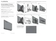
3. Open the inlet cover and remove
the two screws holding the rear
housing. (Fig. C & Fig. D) Remove
the rear housing from the inlet.
(Fig. E)
Fig. C
Fig. D
Fig. E
4. Remove the strain relief insert
and the strain relief ring from the
inside of the rear housing. (Fig. F)
Fig. F
Strain Relief
Insert
Strain Relief
Ring
5. Rotate counterclockwise to remove
the strain relief nut and the cable
clip. (Fig. G)
Fig. G
Cable Clip
6. Strip off 1½” of the outer insula-
tion layer of the cable and 5/8” of
colored insulation from the ends of
the three conductor cables. (Fig. H)
Fig. H
Romex
Wire
Stranded
Core Wire
7. If you are using a Romex Wire,,
thread the cable through the sealing
gasket, strain relief nut, cable clip
and the rear housing. (Fig. I)
Fig. I
Required for Stranded Core Wire
only - If you are using a Stranded
Core Wire, thread the cable through
the sealing gasket, strain relief nut,
strain relief insert, strain relief ring
and the rear housing. (Fig. J)
Fig. J
8. Connect the colored wires to the
corresponding lettered holes on
the back of the inlet and tighten
the terminal screws to 22-25 in-lbs
torque. (Fig. K & Fig. L)
Black
Red
White
Green
Fig. K
22-25 in-lbs
Fig. L
9. Replace the inlet rear housing and
secure with the two screws. Rotate
the rear cap clockwise to fi x the
cables. (Fig. M)
Fig. M
10. Fit the power inlet into the open-
ing and secure with four mounting
screws (not included). (Fig. N)
Housing Screw Size
Stainless KA3.5 x 30
Plastic PA3.5 x 30
Fig. N
Model: F52INS-SS/F52INS-PS/ F52INS-
GS/ F52INS-BS/ F52INR-PS/F52INS-BSN