GE GFDS355ELMS Manual

GE Tørretumbler GFDS355ELMS

Læs gratis den danske manual til GE GFDS355ELMS (16 sider) i kategorien Tørretumbler. Denne vejledning er vurderet som hjælpsom af 36 personer og har en gennemsnitlig bedømmelse på 4.9 stjerner ud af 18.5 anmeldelser. Har du et spørgsmål om GE GFDS355ELMS, eller vil du spørge andre brugere om produktet?

Side 1/16
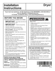
WARNING RISK OF FIRE
• To reduce the risk of severe injury or death, follow all installation
instructions.
• Clothes dryer installation must be performed by a qualied installer.
• Install the clothes dryer according to these instructions and in
accordance with local codes.
• This dryer must be exhausted to the outdoors.
Use only rigid metal 4” diameter ductwork inside the dryer cabinet and use
only UL approved transition ducting between the dryer and the home duct.
• DO NOT install a clothes dryer with exible plastic ducting materials. If
exible metal (semi-rigid or foil-type) duct is installed, it must be UL listed
and installed in accordance with the instructions found in “Connecting
The Dryer To House Vent” on pages 4-5 of this manual. Flexible venting
materials are known to collapse, be easily crushed, and trap lint. These
conditions will obstruct dryer airow and increase the risk of re.
• Do not install or store this appliance in any location where it could be
exposed to water and or weather.
• Save these instructions. (Installers: Be sure to leave these instructions
with the customer).
NOTE: Installation and service of this dryer requires basic
mechanical and electrical skills. It is your responsibility to
contact a qualied installer to make the electrical connections.
Installation
Instructions
Electric Dryer
10
Questions on Installation? Call: 1-800-GECARES (US)
or Visit our Web site at: www.GEAppliances.com (US)
BEFORE YOU BEGIN
Read these instructions completely and
carefully.
IMPORTANT- Save these instructions
for local inspector’s use.
IMPORTANT- Observe all governing
codes and ordinances.
Be sure to leave these Note to Installer -
instructions with the customer.
Keep these instructions Note to Customer -
with your Use and Care Book for future
reference.
• Before the old dryer is removed from service
or discarded, remove the dryer door.
• Service information and the wiring diagram
are located in the control console.
• Do not allow children on or in the appliance.
Close supervision of children is
necessary when the appliance is used
near children.
• Install the dryer where the temperature
is above 50°F for satisfactory operation of
the dryer control system.
TOOLS YOU
WILL NEED
PHILLIPS SCREWDRIVER
SLIP JOINT PLIERS
LEVEL
FLAT BLADE SCREWDRIVER
MATERIALS YOU WILL NEED
GLOVES
SAFETY
GLASSES
DRYER POWER
CORD KIT
(NOT PROVIDED
WITH DRYER)
4" DUCT
CLAMPS (2)
OR
4" SPRING
CLAMPS (2)
EXHAUST
HOOD
3/4" STRAIN
RELIEF
UL RECOGNIZED
4" DIA. ME TAL
ELBOW
4" DIA. FLEXIBLE METAL (SEMI-RIGID)
UL LISTED TRANSITION DUCT
(IF NEEDED)
KIT WX08X10077 (INCLUDES 2 ELBOWS)
4" DIA. METAL DUCT
(RECOMMENDED)
4" DIA. FLEXIBLE METAL (FOIL TYPE)
UL LISTED TRANSITION DUCT
(IF NEEDED.)
DUCT TAPE
UL RATED
120/240V,30A
WITH 3 OR 4 PRONGS.
IDENTIFY THE PLUG
TYPE AS PER THE
HOUSE RECEPTACLE
BEFORE PURCHASING
LINE CORD.
4” COVER PLATE (IF NEEDED
(KIT WE1M454)
31-16629-1 03-11 GE
234D1052P003
Step 1 Prepare the area and exhaust for installation of new dryer
(see section 1).
Step 2 Check and ensure the existing external exhaust is clean (see
section 1) and meets attached installation specications (see
section 3).
Step 3 Remove the foam shipping pads (see section 1).
Step 4 Move the dryer to the desired location.
Step 5 Connect the power supply (see section 2).
Step 6 Connect the external exhaust (see section 4).
Step 7 Level your dryer (see section 5).
Step 8 Check the operation of the power supply and venting.
Step 9 Place the owners manual and the installation instructions in
a location where they will be noticed by the owner.
For alcove or closet installation, see section 6.
For bathroom or bedroom installation, see section 7.
For mobile or manufactured home, see section 8.
For side or bottom exhaust, see section 9.
Installation Instructions
2
Minimum Clearance Other Than Alcove or Closet Installation
Minimum clearance to combustible surfaces and for air opening are: 0 in. clearance both sides, 1 in. front and 3 in. rear.
Consideration be given to provide adequate clearance for installation and service.must
1 PREPARING FOR INSTALLATION
OF NEW DRYER
TIP: Install your dryer before installing your washer.
This will allow better access when installing dryer exhaust.
REMOVING LINT FROM WALL EXHAUST
OPENING
Remove and discard existing plastic or metal foil
transition duct and replace with UL listed transition duct.
2
ELECTRICAL CONNECTION INFORMATION
WARNING - TO REDUCE THE RISK OF
FIRE, ELECTRICAL SHOCK AND PERSONAL INJURY:
• DO NOT USE AN EXTENSION CORD OR AN
ADAPTER PLUG WITH THIS APPLIANCE.
Dryer must be electrically grounded in accordance with
local codes and ordinances, or in the absence of local
codes, in accordance with the NATIONAL ELECTRICAL
CODE, ANSI/NFPA NO. 70.
CONNECTING DRYER USING 4-WIRE
CONNECTION (MUST BE USED FOR
MOBILE HOME INSTALLATION)
NOTE: Since January 1,1996, the National Electric code requires
that the new constructions utilize a 4-wire connection to an
electric dryer.
1. Turn o the circuit breaker (s) (30 amp) or remove the
dryer’s circuit fuse at the electrical box.
2. Be sure the dryer cord is unplugged from the wall
receptacle.
3. Remove the power cord cover located at the lower
back.
4. Remove and discard ground strap. Keep the green
ground screw for step 7.
5. Install 3/4 in. UL recognized strain relief to power cord
entry hole. Bring power cord through strain relief.
6. Connect power cord as follows:
A. Connect the 2 hot lines to the outer screws of
the terminal block (marked L1 and L2).
B. Connect the neutral (white) line to the center of
the terminal block (marked N).
7. Attach ground wire of power cord with the green
ground screw (hole above strain relief bracket). Tighten
all terminal block screws (3) completely.
8. Properly secure power cord to strain relief.
9. Reinstall the cover.
L1
N
L2
RELOC ATE GREEN
GROUND SCREW
HERE
STRAIN
RELIEF
BRACKET
GREEN OR
YELLOW WIRE
3/4", UL
RECOGNIZED
STRAIN RELIEF
HOT
WIRE
SCREWS
(3)
HOT
WIRE
COVER
NEUTRAL
(White)
REMOVE GROUND STRAP
AND DISCARD. KEEP GREEN
GROUND SCREW
4 #10 AWG MINIMUM COPPER
CONDUCTORS OR 120/240V 30A POWER
SUPP LY CORD KIT MARKED FOR USE
WITH D RYERS & PROVIDED WITH
CLOSED LOOP OR S PADE TERMINALS
WITH UPTURNED ENDS (NOT SUPPLIED).
INTERNAL DUCT
OPENING CHECK TH AT EXHAUST
HOOD DAMPER OPENS
AND CLOSES FREE LY.
WALL
TILT THE DRYER SIDEWAYS
AND REMOVE THE FOAM
SHIPPING PADS BY
PULLING AT THE SIDES
AND BREAKING THEM
AWAY FROM THE DRYER
LEGS. BE SURE TO
REMOVE ALL OF THE
FOAM PIECES AROUND
THE LEGS.
ELECTRICAL REQUIREMENTS
This dryer must be connected to an individual branch
circuit, protected by the required time-delay fuses or
circuit breakers. A four or three-wire, single phase,
120/240V or 120/208V, 60Hz, 30 amp circuit is required.
GROUNDING INSTRUCTIONS
This dryer must be connected to a grounded metal, perma-
nent wiring system, or an equipment-grounding conductor
must be run with the circuit conductors and connected to
the equipment grounding terminal on the appliance.
WARNING: NEVER LEAVE THE
COVER OFF OF THE TERMINAL BLOCK.


Produkt Specifikationer

Mærke: GE
Kategori: Tørretumbler
Model: GFDS355ELMS

Har du brug for hjælp?

Hvis du har brug for hjælp til GE GFDS355ELMS stil et spørgsmål nedenfor, og andre brugere vil svare dig


Tørretumbler GE Manualer
GE

GE GTD58GBPVDG Manual

17 Juni 2025
GE

GE GTD58EBPVDG Manual

17 Juni 2025
GE

GE HTX26GASWWW Manual

21 Februar 2025
GE

GE GTD42EASJWW Manual

17 Januar 2025
GE

GE GFDN110EDWW Manual

17 Januar 2025
GE

GE GFD45GSSKWW Manual

17 Januar 2025
GE

GE GFD45GSPKDG Manual

17 Januar 2025
GE

GE GTX42GASJWW Manual

9 Januar 2025
GE

GE GTDS855EDMC Manual

9 Januar 2025

Tørretumbler Manualer

Nyeste Tørretumbler Manualer