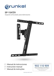
SP-15AT1
Soporte articulado para televisores
Manual de instrucciones
Instruction manual
ES
EN
PT Manual de instruções
GRACIAS POR ESCOGER ESTE PRODUCTO GRUNKEL
GRUNKEL pone a su disposición productos innovadores, duraderos y prácticos. Bajo
un uso responsable y con el mantenimiento adecuado, le proporcionará una larga
vida útil y contribuirá a hacer del día a día una tarea mucho más sencilla.
Agradecemos su conanza y esperamos que disfrute de él.
Descubra el resto de nuestra gama en www.grunkel.com
Este manual es el reproducción en cuanto a características, funcionamiento y estética del producto que usted ha
adquirido salvo error tipográco, de imprenta o traducción. La especicación, funcionamiento y características de
este aparato están sujetos a cambios sin previo aviso.
Este manual é el reprodução em termos de características, operação e estética do produto que você adquiriu,
exceto erro tipográco, impressão ou tradução. A especicação, operação e características deste dispositivo estão
sujeitas a alterações sem aviso prévio.
This instruction manual is an accurate reproduction of the specications, operation and look of the product you
have just bought, except for typographical, print or translation errors. The specications, operation and features of
this product are subject to change without further notice.
• Por favor, lea detenidamente las instrucciones de uso de este
manual al completo antes de ponerlo en funcionamiento.
• Preste especial atención a las indicaciones de seguridad.
• Conserve este manual de instrucciones. Si cede el dispositivo a un
tercero, estas instrucciones también deben ser entregadas
• Guarde también la garantía, el ticket o factura de compra y, si es
posible, la caja con el embalaje interior para posibles solicitudes
en el futuro.
ANTES DE PONER EL PRODUCTO
EN FUNCIONAMIENTO
Tamaño de pantalla: hasta 37”
Carga máxima: 18kg
VESA: 200mm x 200mm máx.
Rango de inclinación: 10° abajo
Rango de giro horizontal: 180°
Perl: de 5,8 a 30cm
Soporte de pared (x1)
Adaptadores (x4)
Manual de instrucciones (x1)
Kit de herramientas (x1)
Lea detenidamente estas instrucciones antes de comenzar. Si no está seguro de alguna
parte del proceso, contacte con un profesional o instalador para ayuda. Una instalación
inadecuada puede derivar en accidentes o lesiones.
La pared o la supercie donde vaya a instalarse el soporte debe soportar el peso combi-
nado del soporte y el televisor. En caso contrario, debe ser reforzada.
EspecicacionesContenido
Medidas de seguridad
LOS DATOS SOBRE CARGA MÁXIMA Y TAMAÑO MÁXIMO ADMITIDOS DE
ESTE SOPORTE DEPENDEN DE CADA MODELO DE TELEVISOR. LA VERACI-
DAD Y SEGURIDAD DE LOS DATOS PROPORCIONADOS POR CADA TELEVI-
SOR SON RESPONSABILIDAD DE SUS RESPECTIVOS FABRICANTES, Y NO
ESTÁN VINCULADAS A LAS ESPECIFICACIONES DE ESTE SOPORTE.
¡ATENCIÓN!
Localice tuberías, cables o cualquier otro peligro en la pared donde desee instalar el
soporte antes de taladrar.
Debe utilizarse equipamiento de seguridad y herramientas apropiadas. En caso contra-
rio podrían producirse accidentes o lesiones.
Se recomienda que la instalación sea llevada a cabo por dos personas. No intente le-
vantar una pantalla pesada sin ayuda.
Siga las instrucciones y recomendaciones referentes a la ventilación adecuada y ubi-
caciones apropiadas para montar su televisor. Consulte el manual de usuario de su
televisor particular para obtener más información.
PRECAUCIÓN: Este soporte ha sido diseñado para uso solo con un peso máximo de
18kg. Su uso con peso superior al indicado puede resultar en inestabilidad causando
posibles lesiones.
Destornillador
Taladro eléctrico o portátil
Broca de 3mm (1/8”) y localizador de vigas para instalación en pared de yeso
Broca de 8mm (5/16”) para instalación en pared de hormigón
Nivel
(A) Tornillos para yeso (x2) (E) Tuerca M6 (x4)
(B) Arandela (x6) (F) Llave S10 (x1)
(C) Espiches (x2) G) Tornillo M4 x 12 (x4)
(D) Tornillo M6 x 12 (x8)
Parte 1A – Montaje en pared (yeso o escayola)
¡IMPORTANTE! Por motivos de seguridad, este soporte debe asegurarse con al menos
dos vigas de madera capaces de soportar el peso combinado del soporte y la pantalla.
Escoja una pared lisa y con suciente grosor. Use un localizador de vigas para localizar
dos vigas adyacentes donde desee instalar su soporte. Marque los dos bordes de am-
bas vigas para identicar el centro exacto.
Herramientas requeridas
Material
Instalación
NOTA: Debe usar el centro de cada viga para evitar agrietamiento o rotura de la madera
durante la instalación.
Utilice un destornillador para quitar la parte frontal del soporte de la parte trasera, como
se muestra en la ilustración (ver. Fig. 1). Coloque el tornillo en un lugar seguro.
Coloque la parte posterior del soporte contra la pared. Asegúrese de que esté nivelada.
Haga dos marcas (una arriba y una abajo) en el centro del soporte para asegurar el
soporte a la pared (ver. Fig. 2) y ajústelo a un lado.
Perfore un agujero de 3 mm (1/8 “) en las dos marcas realizadas como guía.
Coloque el soporte contra la pared y ensámbleo utilizando los tornillos para yeso y dos
de las arandelas (véase gura. 3). No apriete demasiado los tornillos. Asegúrese de que
el soporte esté nivelado.
Parte 1B – Montaje sobre pared (hormigón)
¡IMPORTANTE! Por motivos de seguridad, el muro debe ser capaz de soportar el peso
combinado del soporte y la pantalla. El fabricante no asume responsabilidad por fallo
producido por muros de fuerza insuciente.
Utilice un destornillador para extraer la parte frontal de la montura de la parte trasera
como se muestra en la ilustración (ver. Fig. 1). Coloque el tornillo en un lugar seguro.
Coloque la parte posterior del soporte contra la pared. Asegúrese de que esté nivelada.
Marque dos ubicaciones (una superior y una parte inferior) para asegurar el montaje
en la pared (ver g. 4).
Perfore un agujero de 8 mm (5/16 “) en cada punto marcado. Retire cualquier exceso
de polvo de los agujeros.
Inserte un anclaje de hormigón en cada agujero para que esté al mismo nivel con la
supercie de hormigón (ver. Fig. 5). Se puede utilizar un martillo para jar ligeramente
los anclajes en su lugar si es necesario.
Fig.1 Fig.2 Fig.3
NOTA: si el muro está cubierto por una capa de yeso, el espiche debe pasar comple-
tamente a través de la capa para permanecer a ras con la supercie del hormigón.
Coloque el soporte contra la pared y fíjelo utilizando los tornillos para yeso y dos de las
arandelas, siempre (véase gura. 3). No apriete demasiado los tornillos. Asegúrese de
que el soporte esté nivelado.
Parte 2 – Ensamblar el soporte al televisor
¡IMPORTANTE! Tenga especial cuidado durante esta parte de la instalación. Si es posi-
ble, evite colocar su pantalla hacia abajo p1-ya que podría dañar la supercie.
NOTA: este soporte incluye una selección de tornillos de diferentes diámetros y longi-
tudes para ajustarse a una amplia variedad de modelos de televisor. No todo el mate-
rial en el kit será usado. Si no puede encontrar el tornillo del tamaño adecuado en el kit,
consulte a su proveedor para obtener más información.
Examine los oricios de montaje en la parte posterior de la pantalla:
- Si los agujeros de montaje están espaciados 75 mm x 75 mm ó 100 mm x 100 mm,
omita esta sección y continúe con el paso 2.
- Si los agujeros de montaje están espaciados 100 mm x 200 mm ó 200 mm x 200 mm
entre sí, usted tendrá que utilizar los adaptadores que vienen con el soporte. Conécte-
los al soporte de acuerdo con la ilustración (ver. Fig. 6). Utilice el tornillos M6 x 12 (D),
ruercas de jación M6 (E) y la llave S10 (F) del kit de accesorios.
NOTA: si los agujeros del soporte no quedan alineados con los oricios de la pantalla,
asegúrese de que la pantalla es compatible con VESA. Este soporte sólo puede ser
utilizado con pantallas que sean compatibles con VESA 75, VESA 100, VESA 100x200
o VESA 200. Consulte al proveedor de su televisor para más información.
Determinar el diámetro correcto del tornillo a utilizar. Aconsejamos que cuidadosamen-
te pruebe uno de cada tamaño (M4 y M6) del kit de accesorios. No fuerce los tornillos
- si siente resistencia, cambie este tornillo por uno más pequeño, pero no lo fuerce.
Fig.4 Fig.5
Parte 3 – Ensamblaje nal
Para completar la instalación, levante con cuidado y enganche la parte delantera en
la parte posterior (ver. Fig. 9). No suelte la pantalla hasta que el soporte esté jado de
forma segura.
Vuelva a colocar el tornillo en la parte inferior del soporte y apriete con una destornilla-
dor largo (ver. Fig. 10).
¡IMPORTANTE! Estos tornillos deben de ser apretados al máximo para evitar la caída
accidental de la pantalla
Coloque las tapas de plástico hacia el centro de la estructura, como muestra la gura
11.
Los cables pueden ser enrollados a través del gancho situado en la estructura para
mantenerlos organizados con seguridad.
D
E
Fig.6 Fig.7 Fig.8
Fig.9 Fig.10 Fig.11
Coloque la parte frontal del soporte sobre la parte trasera de su televisor y alinéelo
con los oricios. Asegúrese de que el soporte está orientado tal y como muestra la
ilustración (Fig. 7).
Ensamble el soporte a la pantalla usando los tornillos identicados en el paso anterior.
LOS NIÑOS MENORES DE 8 AÑOS NO DEBEN UTILIZAR NI LIMPIAR ESTE
APARATO SIN LA SUPERVISIÓN DE UN ADULTO. TAMPOCO PUEDE SER
UTILIZADO NI LIMPIADO POR PERSONAS CON CAPACIDADES FÍSICAS,
MENTALES O SENSORIALES REDUCIDAS, SIN EXPERIENCIA O CONOCI-
MIENTO DEL USO DEL MISMO, O QUE NO HAYAN RECIBIDO LA FORMA-
CIÓN ADECUADA BAJO LA SUPERVISIÓN DIRECTA DE UNA PERSONA
CAPACITADA.
¡ATENCIÓN!
Fig.12
Para cambiar el ángulo de inclinación de su televisor, sujete el televisor rmemente
en su lugar y aoje el tornillo de inclinación con un destornillador. Ajuste el televisor
en la posición deseada y apriete de nuevo los tornillos (ver Fig. 12). No suelte el tele-
visor hasta que los tornillos estén totalmente apretados y nunca los retire ni los aoje
totalmente.
PRECAUCIÓN: Tenga cuidado de no pellizcar ningún cable ni sus dedos cuando cam-
bie la inclinación de la pantalla, o al manipular las bisagras y tornillos.
Para poder realizar ajustes giratorios se pueden hacer simplemente moviendo el sopor-
te del televisor a la posición deseada.
Limpie periódicamente su soporte con un paño seco. Inspeccione todos los tornillos y
el material regularmente para asegurarse de que ninguna conexión se p1-ha aojado con
el tiempo. Apriete de nuevo siempre que sea necesario.
Funcionamiento y ajuste
Normas sobre los residuos de los aparatos eléctricos según la DIRECTI-
VA RAEE 2002/96/EC. Este símbolo signica que el presente producto no
puede ser tratado como residuos domésticos normales, sino que debe ser
devuelto al distribuidor, o entregarse en el correspondiente punto de reco-
gida de equipos eléctricos o electrónicos, o llevarlo a un punto de recogida
habilitado a tal n con objeto de que sus componentes sean reciclados y no se mezclen
con la basura doméstica.
También puede avisar al servicio de recogida de su municipio para que sea recogido y
tratado de la forma correspondiente, siguiendo las instrucciones de protección al me-
dio ambiente o para que le aconsejen como hacerlo.
La eliminación de un electrodoméstico signica evitar posibles consecuencias nega-
tivas para el medio ambiente y la salud. Una eliminación adecuada permite obtener
un ahorro importante de energía y recursos. Como un recordatorio de la necesidad de
eliminar por separado los electrodomésticos, en el producto aparece un cubo de basura
con ruedas tachado
Eliminación de la unidad
ENG - Instruction manual
• Please, read carefully the entire instruction manual before using it.
• Pay special attention to the safety indications.
• Keep this instruction manual. If you hand over this applicance to
another person, these instructions must be also be transferred.
• Keep also the guarantee card, purchase ticket or invoice. If
possible, keep the original box with all the accessories included for
future inquiries.
BEFORE PUTTING THE APPLIANCE
INTO OPERATION
Display size: up to 46”
Maximum load: 18kg
Max. mounting pattern: 200 x 200mm
Tilt Range: up to 10° down
Pan/Swivel Range: up to 180°
Prole: 5.8 to 30cm
Mount (x1
Adaptor (x4)
Instruction manual (x1)
Hardware kit (x1)
Read these instructions before you begin. If you are unsure of any part of the process,
contact a professional contractor or installer for assistance. Improper installation can
result in injury or damage.
The wall or mounting surface must be capable of supporting the combined weight of
the mount and the display; if not, the structure must be reinforced.
SpecicationsContent
General safety instructions
WARNING!
THE INFORMATION RELATED TO MAXIMUM LOAD AND MAXIMUM SIZE
SUPPORTED BY THIS MOUNT DEPEND ON EACH TV MODEL INDIVIDUALLY.
THE TRUTHFULNESS AND SAFETY OF THE PROVIDED INFORMATION ARE
THE SOLE RESPONSIBILITY OF THEIR RESPECTIVE MANUFACTURERS,
AND ARE NOT ASSOCIATED WITH THIS PRODUCT IN ANY WAY.