Hager REU310X Manual
Hager
Ikke kategoriseret
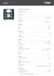
REU310X

| Mærke: | Hager |
| Kategori: | Ikke kategoriseret |
| Model: | REU310X |
Har du brug for hjælp?
Hvis du har brug for hjælp til Hager REU310X stil et spørgsmål nedenfor, og andre brugere vil svare dig
Ikke kategoriseret Hager Manualer
10 August 2025

10 August 2025
10 August 2025
10 August 2025

10 August 2025
10 August 2025
10 August 2025

10 August 2025

10 August 2025
10 August 2025
Ikke kategoriseret Manualer
- LEX
- BRIO
- Einhell
- Black Line
- Juniper
- DPM
- Virax
- Bobrick
- Meccano
- Life Fitness
- Pichler
- APPS2Car
- Duracell
- Dinex
- Sanwa
Nyeste Ikke kategoriseret Manualer

11 December 2025

11 December 2025

11 December 2025

11 December 2025

11 December 2025

11 December 2025

11 December 2025

11 December 2025

11 December 2025

11 December 2025