zKNX-DALI-2-Gateway
tunable white
iKNX-DALI-2-Gateway
wit moduleerbaar
TYA670WD2
6LE007599A 82596916
TYA670WD2
Area
Li ne
Ptcp.
Nb.
Made in G e rmany
TP/S30V
s
110-240V s
110-240V v
50/60 Hz
Description
Da+ Da- L N
TYA670WD2
Area
Line
Ptcp.
Nb.
Made in GermanyTP/S30V s
110-240V s
110-240V v
50/60 Hz
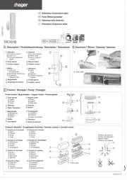
1 Keyboard for manual control
2 Push Button and LED indicator for addressing
3 KNX Connection
4 Display of DALI numbers
5 Connection to the network
6 DALI connection.
Operating mode
Control Elements
TYA670WD2
Area
Line
Ptcp.
Nb.
Made in Germany
TP/S30V s
110-
110
50/
4 Display of the DALI numbers
- 4
a
DALI Groups (1...32)
- 4
b
Individual participants (1...64)
- bc : If the display shows bc (broadcast
operation), the device is not programmed or set
to master control in the KNX configuration. All
DALI devices are then controlled jointly.
7 Key : manual control
8 LED on : Manual mode permanently enabled
9
Key : Turn on or adjust the light intensity
brighter
A LED on : Individual participant or DALI group
enabled : light intensity 1…100%
Z
Key : Turn o or adjust the light intensity
darker
E LED on : Individual participant or DALI group
disabled: light intensity 0%
R
Key
: Turn o all DALI participants.
Operating mode
Bus mode controls via push button
Short-term
manual mode
manual control using the
keyboard, automatic return to
bus mode
Permanent
manual mode
manual control exclusively via
the gateway
H- In manual mode, a bus mode is not possible.
- In the event of a failure of the bus, manual
control is possible.
- After the bus failure and a return to service, the
device operates in bus mode.
- After a power cut and a return to service, the
gateway operates in bus mode.
- Manual mode is disabled by a telegram in current
mode.
Enabling short-term manual mode
The operation of the keyboard is programmed and
is not locked.
- Press the key briefly (<1 second). 01 is
displayed on the screen, the LED remains
o or
is displayed on the screen (refer to ). In this bc
mode, individual control of the participants is not
possible.
Disabling short-term manual mode
The gateway is in short-term manual mode.
- No manipulation for 5 seconds
or
- Short press on the key (<1 second) until
the gateway exits short-term manual mode. The
display turns o.
Enabling permanent manual mode
The operation of the keyboard is programmed and
is not locked.
- Press the key for at least 5 seconds.
The LED is lit, is displayed on the screen, 01
permanent manual mode is enabled.
or
- is displayed on the screen (refer to ).bc
Disabling permanent manual mode
- Press the key for at least 5 seconds.
The LED turns o and bus mode is enabled.
Controlling the DALI participants
The gateway is in permanent or short-term manual
mode.
-
Press briefly on the key ( < 1 second) until the
number of the desired DALI participant is displayed
The and LEDs display the status.
- Control the DALI participant with the key or
with the key Short press : turns on and o
Long press : varies the light intensity brighter/
darker
The and LEDS display the status.
- In permanent manual mode, after having
been through all the available DALI participant
Product description
The DALI-2 KNX gateway is used to interface DALI
and DALI-2 lighting applications with the KNX system.
Function
System information
This device is a product of the KNX system and
complies with the KNX directives. Detailed technical
knowledge obtained in KNX training courses is a
prerequisite to proper undertsanding… The function
of this device depends upon the software. Detailed
information on loadable software and attainable
functionality as well as the software itself can be
obtained from the manufacturer's product
dartabase.
Planning, installation and commissioning of the
device are carried out with the aid of KNX-certified
software. Full functionality with KNX commissioning
software version ETS5 onwards.
An updated version of the product database,
technical descriptions and conversion programs
and other auxiliary programs are availbale on our
internet website.
Product characteristics
• Controls up to 64 DALI, DALI-2 products in up to 32
groups
• Individual control, group control or general control
• Setting the color temperature for luminaires
withDALI operating device Type 8 for Tunable
White in accordance with IEC 62386-209
• 16 scenes
• Eect control for dynamic sequences and sets of
colours
• Reading of the status of DALI products via KNX,
e.g. light intensity, light fitting fault, etc.
• Manual control of DALI groups
• Priority
• Feedback on the status of switching and the
value of light intensity in bus mode and manual
mode
• General status feedback
• General command function
• Emergency lighting function
• Inhibition function for each group
• Separate switching and tripping delay
• Timer function with cut-o pre-warning
• Movement function : in combination with a
presence detector, reduction of the light intensity
when no movement is detected before turning o
• Online or oine commissioning of DALI products
with ETS plug-ins
• Surge protection and overload protection
• Possibility to replace an individual DALI product
without software during service
• Operating hours counter
• Delivery status : job-site mode, possibility of
ordering DALI groups using the keyboard. All
DALI products are ordered jointly.
• Signal of the global switching status of the DALI
devices, e.g. to switch o the mains voltage of
the DALI devices to avoid stanby losses.
numbers, the gateway exits manual mode after an
additional press.
Turning o all the DALI participants
The gateway is in permanent manual mode.
- Press the
key.
All DALI participants are switched o.
Locking the DALI participants or groups
individually
The gateway is in permanent manual mode.
- Press briefly on the key ( < 1 second) until the
desired DALI number is displayed.
The and LEDs display the status.
- Press the and keys simultaneously for at
least 5 seconds.
The DALI number selected flashes on the display
screen.
The DALI participant or group is locked.
- Enable bus mode (leaving permanent manual
mode).
A locked DALI participant can be controlled in
manual mode.
Unlocking the DALI participants or groups
individually
The gateway is in permanent manual mode
- Press briefly on the key (<1 second) until the
desired DALI number is displayed.
- Press the and keys simultaneously for at
least 5 seconds.
The DALI participant or group is released.
The display on the screen no longer flashes.
- Enable bus mode (leaving permanent manual
mode).
HAny additional DALI power is prohibited!
Connection
TYA670WD2
Area
Line
Ptcp.
Nb.
Made in GermanyTP/S30V s
110-240V s
110-240V v
50/60 Hz
230 V 50/60 Hz
L1
L2
L3
N
da+
da -
da da N L da da N L
Bus 30 V
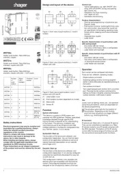
Electrical connection
Connect the device according to the diagram above.
Observe the temperature range. Ensure adequate
cooling.
When performing installation, perform the
installation in such a way that when the area is
disconnected the lines carrying both the DALI and
also the mains voltage are disconnected.
If multiple circuit breakers supply dangerous
voltages to the device or load, couple the miniature
circuit breakers or label them with a warning, to
ensure disconnection is guaranteed.
DALI devices from some manufacturers have
expanded functions and can be controlled. In the
case of upgrades of existing DALI installations,
remove all the corresponding control devices.
The DALI control voltage is a functional extra-low
voltage (FELV).
Types of compatible ballast
Under the IEC standard, ballasts are classified
based on their Device Type (DT).
Below is a list of DTs that are compatible with the
product:
DT0 = fluorescent lamp
DT2 = discharge lamp
DT3 = low-voltage halogen lamp
DT4 = power supply voltage regulator for
incandescent lamps
DT5 = DC voltage digital signal converter
DT6 = LED modules
DT7 = switching function (ON / OFF only)
DT8 = colour and colour temperature
H
The total length of the DALI command line
installed is considered the maximum length
here.
Operation of the emergency lighting
The device can be used in centrally-powered
emergency lighting systems.
G
The statutory and standard specifications vary
from country to country. In any event, the user /
technical planner should check whether the specific
specifications should be maintained.
G Observe the number of DALI devices in the
emergency luminaires used.
Emergency lighting systems with a central safety
supply are required in buildings larger than 2000 m².
Depending on the scope of functions of the system,
only the emergency luminaires are supplied by the
central safety supply (figure 1), or the KNX system
and DALI-2 gateway are also supplied (figure 2). In
the latter case, in emergency operation, the DALI-2
gateway can transmit the appropriate fault messages
to a central system and other DALI-2 gateways in the
system.
Figure 1 : Emergency lighting supplied by the
central emergency power supply
AC 230 V
C/DC 230 V
KNX
L, N
da
KNX
DALI
DALI
L, N
da
Figure 2 : Emergency lighting, KNX supply and
the DALI-2 gateway are supplied by the central
emergency power supply circuit.
C/DC 230 V
KNX
*L, N
da
KNX
DALI
DALI
L, N
da
*The KNX power supply must be adapted to the
voltage of the AC / DC safety source.
Commissioning
Downloading the physical address and the
application software
- Supply power to the product from the mains
- Connect the KNX bus
- Download the physical address
- Commission DALI system using commissioning
software
- Download the application software into the device
6LE007599A 2 6LE007599A1
Programming is not possible if the product is not
powered via the mains.
Technical data
Supply
Rated voltage 110 ... 240 V v
Mains frequency 50 / 60 Hz
Rated voltage DC 110 ... 240 V s
Power loss max. 3 W
Ambient conditions
Operating tempertaure -5 ... +45 °C
Storage /transport temperature -25 ... +70 °C
DALI
DALI power supply voltage 6 V FELV s
Number of participants max 64
DALI EN62386 protocol
Guaranteed current 128 mA
Maximum current 250 mA
Cable type Sheathed cable 230V e.g. NYM
Start-up timev <11 ms
DALI cable lenght
with Ø 1,5 mm² max. 300 m
with Ø 1,0 mm² max. 238 m
with Ø 0,75 mm² max. 174 m
with Ø 0,5 mm² max. 116 m
The total length of the DALI command line
installed is considered the maximum length here.
Housing
Fitting width 72 mm / 4 modules
Connection of power supply and DALI
Connection mode Screw terminal
single stranded 0,5 ... 4 mm²
Finely strande without conductor sleeve 0,5 ... 4 mm²
Finely strande with conductor sleeve 0,5 ... 2,5 mm²
KNX
KNX Medium TP
Commissionning mode S Mode
Rated voltage KNX 21 ... 32 V SELVs
Power consumption KNX typ. 150 mW
Connection type for bus KNX Terminal
This manual is an integral part of the product
and must be kept by the end user.
Correct Disposal of This product
(Waste Electrical & Electronic Equipment).
(Applicable in the European Union and other European
countries with separate collection systems).
This marking shown on the product or its literature indicates that
it should not be disposed with other household waste at the end
of its working life. To prevent possible harm to the environment or
human health from uncontrolled waste disposal,
please separate this from other types of waste and recycle it re-
sponsibly to promote the sustainable reuse of material resources.
Household users should contact either the retailer where they
purchased this product, or their local government oce, for details
of where and how they can take this item for environmentally safe
recycling.
Business users should contact their supplier and check the terms
and conditions of the purchase contract. This product should not
be mixed with other commercial waste for disposal.
Usable in all Europe M and in Switzerland
What to do if…
The screen displays , the connected DALI devices have no
functions, no control is possible
Cause : network voltage on the
DALI bus Solution : correct the
installation wiring fault
The screen displays bc in manual mode, control of some light
fittings is not possible.
Cause : the device has not
been programmed or is
programmed to "Broadcast"
Solution :
program the
gateway, commission the DALI
system
Individual DALI devices have no function
Cause 1 : Load is defective,
e.g. lamp
Solution : Exchange load
Cause 2 : DALI device is
defective
Solution : Exchange defective
device and switch on voltage
Press buttons 7 and 13 together for at least 10 seconds.
The device detects the exchanges DALI-2 device and loads in the
necessary data. The display shows
LE
.
G Simultaneous exchange of multiple DALI devices is only
possible with commissioning software and project data.
None of the DALI groups can be operated
Cause 1 : All DALI groups
disabled via bus or manual
operation
Solution : Cancel disabling
Cause 2 : Continuous manual
mode switched on
Solution : Deactivating permanent
manual control
Cause 3 : Application
software has been stopped,
programming LED is flashing
Solution : Perform reset:
Disconnect device from bus,
switch on again after approx. 5
seconds
Cause 4 : Application software
missing or faulty
Solution : Check programming
and correct
q• Electrical equipment must be installed and fitted by
qualified electricians only.
• Failure to observe the instructions may cause
damage to the device and result in fire or other
hazards
• This device is not suitable for disconnection of the
mains power supply.
• Risk of electric shock: always disconnect the mains
supply before working on the device or on load. Cut
in particular all circuit breakers that provide voltages
dangerous to the device or load.
• The DALI control voltage is a functional extra-low
voltage (FELV). During the installation, ensure there
is a safe separation between KNX and DALI.
• DALI-2 and interoperability: Interoperability
(guaranteed compatibility with all DALI equipment)
and certification (the product's guaranteed
interoperability with ones made by a dierent
manufacturer) are what distinguish DALI-2 from the
previous DALI version
• Note: This product is DALI-2 certified. In the event
of a fault, please check that the ballasts controlled
are DALI-2 certified.
:.?nB