Hager WST316T Manual
Hager
Ikke kategoriseret
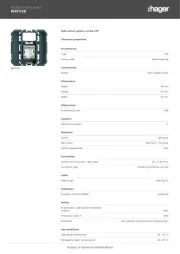
WST316T

| Mærke: | Hager |
| Kategori: | Ikke kategoriseret |
| Model: | WST316T |
Har du brug for hjælp?
Hvis du har brug for hjælp til Hager WST316T stil et spørgsmål nedenfor, og andre brugere vil svare dig
Ikke kategoriseret Hager Manualer
10 August 2025

10 August 2025
10 August 2025
10 August 2025

10 August 2025
10 August 2025
10 August 2025

10 August 2025

10 August 2025
10 August 2025
Ikke kategoriseret Manualer
- SteelBody
- Saba
- MORryde
- Maretron
- BLUEPALM
- Polarlite
- NUX
- Wallas
- Origin Effects
- Acoustic Solutions
- DeWalt
- Potenza
- LandRoller
- Miomare
- Hobart
Nyeste Ikke kategoriseret Manualer

11 December 2025

11 December 2025

11 December 2025

11 December 2025

11 December 2025

11 December 2025

11 December 2025

11 December 2025

11 December 2025

11 December 2025