Hager WXT314 Manual


Læs gratis den danske manual til Hager WXT314 (4 sider) i kategorien Ikke kategoriseret. Denne vejledning er vurderet som hjælpsom af 41 personer og har en gennemsnitlig bedømmelse på 4.1 stjerner ud af 21 anmeldelser. Har du et spørgsmål om Hager WXT314, eller vil du spørge andre brugere om produktet?

Side 1/4
1
6LE005164B
WXT30x
Gallery push-button, Tebis KNX bus,
xrockers, xinputs
WXT31x
Gallery push-button, Tebis KNX bus,
xrockers, xinputs with LED
WXT32x
Gallery push-button, Tebis KNX bus,
xrockers, xinputs with LED + 12 IR inputs
Safety instructions
Electrical equipment may only be installed and
assembled by a qualified electrician. Always
follow the relevant accident prevention
regulations of the country.
Failure to comply with these installation
instructions may result in damage to the
device, fire or other hazards.
When installing and laying cables, always
comply with the applicable regulations and
standards for SELV electrical circuits.
These instructions are an integral component
of the product and must be retained by the end
user.
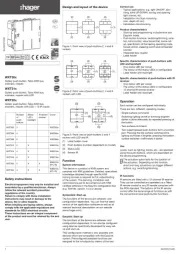
Design and layout of the device
Figure 1: Front view of push-buttons 2, 4 and 6
rockers
Figure 2: Front view of push-buttons 2, 4 and 6
rockers with LED
Figure 3:
Front view of push-buttons 2 and 4
rockers with LED and IR
(1) Label holder cover
(2) Push-buttons (number dependent on model)
(3) Status LED
(4) Sensor IR
Function
System information
This device is a product of KNX system and
complies with KNX guidelines. Detailed, specialised
knowledge obtained through specific KNX
training courses is required for full understanding
of the system. The planning, installation and
commissioning are to be carried out with KNX-
certified software or the Easylink configuration tool
(e.g. TXA100, version 1.5.0 or above).
Systemlink: Start-up
The functions of the device are software- and
configuration-dependent. You can find the latest
version of the application software as well as all
relevant technical descriptions on our website
(www.hager.com).
Easylink: Start-up
The functions of the device are software- and
configuration-dependent. It can also be configured
using devices specifically developed for easy set-
up and start-up.
This configuration method is only possible with
devices which are compatible with the Easylink
system. Preconfigured standard functions are
assigned to the in/outputs by means of the tool.
Correct use
-Typical applications: e.g. light ON/OFF, dim-
ming, blind UP/DOWN, saving and opening
light scenes, etc.
-Installation into flush mounting
(min. depth 40 mm)
-Installation into truncking
Product characteristics
-Start-up and programming in Systemlink and
Easylink mode
-Push-button functions: switching/dimming, varia-
tion, blind control, value transmitter, scene call-
up, specification of the heating operating mode,
forced control, stepping switch and comparator
function
-Integrated bus coupler
-Label holder
Specific characteristics of push-buttons with
LED and backlight
-One status LED per rocker
-The colour of the status LEDs is configurable
-Label holder with backlight
Specific characteristics of push-buttons with IR
receiver
-One status LED per rocker
-The colour of the status LEDs is configurable
-12-channel IR remote receiver
-Label holder with backlight
Operation
Each rocker can be configured individually.
There are two, dierent, operating modes:
- Single-surface command:
Switching lighting on/o or dimming brighter/
darker is done alternately by repeated pressing of
the button.
- Two-surface command:
Two superimposed push-buttons form a function
pair. Pressing the top surface switches/dims
lighting on/makes it brighter; pressing the bottom
surface switches it o/makes it darker.
Use
Loads, such as lighting, blinds, etc., are operated
using the push-buttons, which are dependent on
the device programming.
The actuation pulse lasts for the duration of
the actuation. Depending on the function,
short and long actuations can trigger dierent
actions, e.g. switching/dimming.
IR functions
IR devices are fitted with a 12 channel IR receiver.
They can be controlled and operated via a Tebis
IR remote control or any IR remote compliant with
the RC6 standard. The buttons of the IR remote
control oer the same range of functions as with
the conventional local push-button functions.
G
z
i
Number
of
push-
buttons
Status
LED +
backlight
IR remote
receiver
Cover
WXT302 2 WXE302x
WXT304 4 WXE304x
WXT306 6 WXE306x
WXT312 2 X WXE312x
WXT314 4 X WXE314x
WXT316 6 X WXE316x
WXT322 2 X X WXE312x
(FPL IR)
WXT324 4 X X WXE314x
(FPL IR)
6LE005164B
(2)
(2)
(1)
(2)
(2)
(1)
(2)
(2)
(1)
(3)
(3)
(1)(2)
(3)
(3)
(1)(2)
(3)
(3)
(1)
(2)
(3)
(3)
(1)
(2)
(3)
(3)
(1)
(2) (4) (4)
Information for electricians
Installation and electrical connection
Foreword
By default all devices are equipped with a pro-
tection cover that lets you use the product before
inserting the trim.
Mounting
Proceed as follows
zScrew the supporting frame (7) on to the
flush-mounting box which must have a min.
depth of 40 mm
Note the HAUT/TOP marking.
zConnect bus cable to the product with the
terminal block (provided in the box).
zMount push-button (4.2) on the supporting
frame (7). Note the HAUT/TOP marking.
Mounting in trunking:
zCircuit bus connection cable to push-button
(4.2) with the terminal block, directly in trunck-
ing until it locks into place. Note the HAUT/TOP
marking.
Start-up
Systemlink
zSet the desired settings in ETS.
zSwitch on bus voltage.
zPress programming button (5).
zThe programming LED (5) lights up.
G If the programming LED does not light up, there
is no bus voltage.
zLoad the physical address and application
software from ETS.
G
The physical address is only ever assigned for
one device. Only one device can ever be
in programming mode.
zThe programming LED (5) goes out.
G
Flashing status LEDs (3) indicate the application
software which has been loaded is not
compatible.
Easylink
zThe device must be mounted on the bus cou-
pling unit for Easylink mode start-up.
zPlease refer to the detailed description of the
"Easylink" service module for more information
on the configuration of the installation.
Mounting the trim
zSwitch o bus voltage.
zRemove protection cover.
zClip on trim (4.1).
zMount design plate (6).
Dismantling
zSwitch o bus voltage.
zRemove design plate (6).
zRemove push-button (4.2) from support (7),
using the notches 4.2.1 (top and bottom). Hold
on to the design plate.
zDisconnect bus line from push-button.
Comments
Changing label holder inlay
For push-buttons (4.2) with IR, the trim (4.1) is
supplied with an adapted label holder inlay (1.3).
Proceed as follows
zUnclip the label holder cover (1.1) as well as
the label holder inlay (1.2).
zReplace label holder inlay (1.2) with (1.3).
zClip on label holder cover (1.1).
Configuration mode with trim
zRemove label holder cover (1.1) to access the
programming button (5).
Appendix
Technical data
KNX Medium TP 1
Start-up mode Smode, Hager Easylink controller
Rated voltage KNX 30V SELVs
Current consumption KNX type 20 mA
Connection mode KNX bus connecting terminals
Dimensions (W x H x D) 45 x 45 x 28 mm
Degree of protection IP20
Protection class III
Operating temperature -5 ... +45°C
Storage/transport temperature -20 ... +70°C
Troubleshooting
Bus operation is not possible.
Cause: Bus voltage is not present.
Check bus connection terminals for correct polarity.
Check bus voltage by briefl y pressing the
programming button (5), red programming LED
lights up if bus voltage is present.
All status LEDs flashing
Cause: The loaded application program and appli-
cation module are not compatible.
Install new application program or mount suit-
able application module
Accessories
Sheet of labels for labelling field WST900
Bus connector TG008
Infrared remote control EE809
Trim See correlation table
on first page
Touching live parts can result in an electric
shock!
An electric shock can be lethal!
Disconnect the connecting cables before
working on the device and cover all live
parts in the area!
Correct Disposal of This product
(Waste Electrical & Electronic Equipment).
(Applicable in the European Union and
other European countries with separate
collection systems).
This marking shown on the product or its literature
indicates that it should not be disposed with other
household waste at the end of its working life. To
prevent possible harm to the environment or human
health from uncontrolled waste disposal,
please separate this from other types of waste and
recycle it responsibly to promote the sustainable
reuse of material resources.
Household users should contact either the retailer
where they purchased this product, or their local
government oce, for details of where and how they
can take this item for environmentally safe recycling.
Business users should contact their supplier and
check the terms and conditions of the purchase con-
tract. This product should not be mixed with other
commercial waste for disposal.
Usable in all Europe and in Switzerland M
Figure 4 : Mounting the product
(1.1) Label holder cover
(1.2) Label holder inlay for push-button with and without LED
(1.3) Label holder inlay for IR push-button IR receiver
(4.1) Trim (not supplied)
(4.2) Push-button
(4.2.1) Notches to unclip
(5) Illuminated programming button
(6) Design plate (not supplied)
(7) Supporting frame (not supplied)
2 6LE005164B
This device must be installed according
to the installation standards in force
in the country.
(7)
(5)
(1.1)
(1.3)
(1.2)
(4.1)
(4.2.1)
(6) (4.2)


Produkt Specifikationer

Mærke: Hager
Kategori: Ikke kategoriseret
Model: WXT314

Har du brug for hjælp?

Hvis du har brug for hjælp til Hager WXT314 stil et spørgsmål nedenfor, og andre brugere vil svare dig


Ikke kategoriseret Hager Manualer
Hager

Hager CEA225U Manual

10 Juni 2025
Hager

Hager CFA263U Manual

10 Juni 2025
Hager

Hager ADZ366C Manual

10 Juni 2025
Hager

Hager LLD100 Manual

12 Januar 2025
Hager

Hager GS11019016 Manual

30 December 2025
Hager

Hager EG203 Manual

30 December 2025
Hager

Hager MZN131 Manual

30 December 2025
Hager

Hager FN097E Manual

30 December 2025
Hager

Hager FN117E Manual

30 December 2025

Ikke kategoriseret Manualer

Nyeste Ikke kategoriseret Manualer