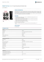
Product Information
1
2
43
Wireless Siren
8
1
7
23
4
56
CONTROL
PANEL
1
3 4 5
2
3
3
a
b
BUCKLE
PIN1
Mode B (Default) Mode B (Default)
PIN2 PIN3 PIN1 PIN2 PIN3
a
b
c
BATTERY POWER
Control Panel Siren Input
12 VDC POWER
COPYRIGHT ©2019 Hangzhou Hikvision Digital Technology Co., Ltd.
ALL RIGHTS RESERVED.
Any and all informaon, including, among others, wordings, pictures,
graphs are the properes of Hangzhou Hikvision Digital Technology Co.,
Ltd. or its subsidiaries (hereinaer referred to be “Hikvision”). This user
manual (hereinaer referred to be “the Manual”) cannot be reproduced,
changed, translated, or distributed, parally or wholly, by any means,
without the prior wrien permission of Hikvision. Unless otherwise
spulated, Hikvision does not make any warranes, guarantees or
representaons, express or implied, regarding to the Manual.
About this Manual
This Manual is applicable to Wireless Outdoor Siren.
The Manual includes instrucons for using and managing the product.
Pictures, charts, images and all other informaon hereinaer are for
descripon and explanaon only. The informaon contained in the Manual
is subject to change, without noce, due to firmware updates or other
reasons. Please find the latest version in the company website
(hp://overseas.hikvision.com/en/).
Please use this user manual under the guidance of professionals.
Trademarks Acknowledgement and other Hikvision’s
trademarks and logos are the properes of Hikvision in various jurisdicons.
Other trademarks and logos menoned below are the properes of their
respecve owners.
Legal Disclaimer
TO THE MAXIMUM EXTENT PERMITTED BY APPLICABLE LAW, THE PRODUCT
DESCRIBED, WITH ITS HARDWARE, SOFTWARE AND FIRMWARE, IS PROVIDED
“AS IS”, WITH ALL FAULTS AND ERRORS, AND HIKVISION MAKES NO
WARRANTIES, EXPRESS OR IMPLIED, INCLUDING WITHOUT LIMITATION,
MERCHANTABILITY, SATISFACTORY QUALITY, FITNESS FOR A PARTICULAR
PURPOSE, AND NON-INFRINGEMENT OF THIRD PARTY. IN NO EVENT WILL
HIKVISION, ITS DIRECTORS, OFFICERS, EMPLOYEES, OR AGENTS BE LIABLE TO
YOU FOR ANY SPECIAL, CONSEQUENTIAL, INCIDENTAL, OR INDIRECT
DAMAGES, INCLUDING, AMONG OTHERS, DAMAGES FOR LOSS OF BUSINESS
PROFITS, BUSINESS INTERRUPTION, OR LOSS OF DATA OR
DOCUMENTATION, IN CONNECTION WITH THE USE OF THIS PRODUCT, EVEN
IF HIKVISION HAS BEEN ADVISED OF THE POSSIBILITY OF SUCH DAMAGES.
REGARDING TO THE PRODUCT WITH INTERNET ACCESS, THE USE OF
PRODUCT SHALL BE WHOLLY AT YOUR OWN RISKS. HIKVISION SHALL NOT
TAKE ANY RESPONSIBILITES FOR ABNORMAL OPERATION, PRIVACY LEAKAGE
OR OTHER DAMAGES RESULTING FROM CYBER ATTACK, HACKER ATTACK,
VIRUS INSPECTION, OR OTHER INTERNET SECURITY RISKS; HOWEVER,
HIKVISION WILL PROVIDE TIMELY TECHNICAL SUPPORT IF REQUIRED.
SURVEILLANCE LAWS VARY BY JURISDICTION. PLEASE CHECK ALL RELEVANT
LAWS IN YOUR JURISDICTION BEFORE USING THIS PRODUCT IN ORDER TO
ENSURE THAT YOUR USE CONFORMS THE APPLICABLE LAW. HIKVISION
SHALL NOT BE LIABLE IN THE EVENT THAT THIS PRODUCT IS USED WITH
ILLEGITIMATE PURPOSES.
IN THE EVENT OF ANY CONFLICTS BETWEEN THIS MANUAL AND THE
APPLICABLE LAW, THE LATER PREVAILS.
2006/66/EC (baery direcve): This product contains a baery
that cannot be disposed of as unsorted municipal waste in the
European Union. See the product documentaon for specific
baery informaon. The baery is marked with this symbol,
which may include leering to indicate cadmium (Cd), lead (Pb),
or mercury (Hg). For proper recycling, return the baery to your
supplier or to a designated collecon point. For more informaon
see:www.recyclethis.info
This product and - if applicable - the supplied accessories too are
marked with "CE" and comply therefore with the applicable
harmonized European standards listed under the RE Direcve
2014/53/EU, the EMC Direcve 2014/30/EU, the LVD Direcve
2014/35/EU, the RoHS Direcve 2011/65/EU.
2012/19/EU (WEEE direcve): Products marked with this symbol
cannot be disposed of as unsorted municipal waste in the
European Union. For proper recycling, return this product to your
local supplier upon the purchase of equivalent new equipment, or
dispose of it at designated collecon points. For more informaon
see: www.recyclethis.info
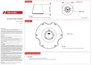
221mm
45mm
37mm
215mm
9
EN50131-4:2009
EN50131-5-3:2017
EN50131-6:2017
Security Grade 2
Environmental Class II
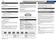
PIN1 PIN2 PIN3
a
b
c
Mode A
…… ……
Control Panel Terminal
Siren
Terminal
-12V
485+ 485- G G12V_BELL12V_AUX
Power on the security control panel. Press the funcon
buon once and then press the registraon key. Add the
siren according to the voice prompt. The green LED of the
siren will flash 8 mes aer being successfully enrolled.
Note: The distance between the security control panel and
the siren should be less than 50 cm.
Enroll the Siren Locally
1.Check Signal Strength
Enter the signal checking mode, and then hold the registraon key
for 1 to 2 s.
Solid Green for 3 s - Strong Signal (appropriate for installaon)
Solid Red for 3 s - Weak Signal
Off-No Signal
Indicator
Operaon:
Armed: Blue LED flashes once.
Disarmed: Blue LED flashes twice.
Formaed: Red LED flashes 3 mes, interval:200 ms.
Enrolled: Green LED flashes 8 mes, interval:200 ms.
Display Signal Strength:
Enter the signal strength checking mode, and then hold the
registraon key for 1 to 2 s:
Solid Green for 3 s - Strong Signal
Solid Red for 3 s - Weak Signal
Installaon
2.Loosen the set screw at the boom of the siren and
remove the front panel.
Note: You can hang the front panel on the buckle.
3.Aach the siren to the required place with the top
screw. Make the siren horizontal by resorng to the
gradienter.
4.Secure the siren with other three screws.
5.Fix the front panel on the siren body. Tighten the set
screw to complete the installaon.
English
Diagram Reference
Specification
1
TAMPER
Tampering Alarm: If the siren is disassembled, an alarm
will be triggered.
Appearance
1
Power On
2
4
Enrollment
3
Buzzer
Zone Alarm:Rapid high frequency impulsive sound.
Panic Alarm: High and low frequemcy alternated
impulsive sound.
Fire Alarm:Fire bell.
Armed: One beep.
Disarmed: Two beeps (1s gap).
Note: You can sign in web client “Device Management -
Siren - Sengs” “wireless Device” to or the mobile client
adjust the volume of buzzer.
1.Loosen the set screw at the boom of the siren and
remove the front panel.
Note: You can hang the front panel on the buckle.
2. Open the water-proof cover.
3. Power the siren on.
4. Close the water-proof cover.
Baery Power
a. Plug the jumper cap to pin2 and pin3 (mode B).
b. Install four
CR123A
baeries according to the polarity mark.
Note: Do not reverse the polarity of the baery.
12 VDC Power
a. Plug the jumper cap to pin2 and pin3(mode B).
b. Push the Cable Knock-Out away.
c. Wire the power cable.
a. Plug the jumper cap to pin1 and pin2(mode A).
b. Push the Cable Knock-Out away.
c. Connect to the control panel siren terminal.
Water-Proof Transparency Cover Buzzer
Power Terminal
Baery Connector Registraon Key
Gradienter
3 5
2
4
6
TAMPER
7
Strobe Light
8
Power
Int facer e
9
Indicator
Mode A Control Panel Siren Input:
Mode B Baery or 12 VDC Input:
UD14978B-A
Références du schéma
Français
Referências do diagrama
Português
Registre a sirene localmente
Ligue o painel de controle de segurança. Pressione o botão função
uma vez e, em seguida, pressione a tecla de registro. Adicione a
sirene de acordo com o comando de voz. O LED verde da sirene
piscará 8 vezes após um registro bem-sucedido.
Observação: A distância entre o painel de controle de segurança e a
sirene deve ser menor que 50 cm.
1. Verificar a intensidade do sinal
Entre no modo de verificação do sinal e pressione a tecla de registro
durante 1 ou 2 segundos.
Aceso em verde por 3 segundos - sinal forte (adequado para
instalação)
Aceso em vermelho por 3 segundos - sinal fraco
Apagado - sem sinal
2. Afrouxe o parafuso de ajuste na parte inferior da sirene e rere o
painel frontal.
Observação: Você pode pendurar o painel frontal na alça.
3. Fixe a sirene no local desejado com o parafuso na parte superior.
Coloque a sirene na horizontal fazendo uso do nível.
4. Fixe a sirene com os outros três parafusos.
5. Fixe o painel frontal no corpo da sirene. Aperte o parafuso de
ajuste para finalizar a instalação.
1
VIOLAÇÃO
Alarme de violação: Se a sirene for desmontada, será disparado um
alarme.
Indicador
Operação:
Armado: LED azul pisca uma vez.
Desarmado: LED azul pisca duas vezes.
Formatado: LED vermelho pisca 3 vezes. Intervalo: 200 ms.
Registrado: LED verde pisca 8 vezes. Intervalo: 200 ms.
Exibir a Intensidade do Sinal:
Entre no modo de verificação da intensidade do sinal e pressione a
tecla de registro durante 1 ou 2 segundos:
Aceso em verde por 3 segundos - sinal forte
Aceso em vermelho por 3 segundos - sinal fraco
Campainha
Alarme de zona: som impulsivo rápido de alta frequência.
Alarme de pânico: som impulsivo de alta e baixa frequências
alternadamente.
Alarme de incêndio: sino de incêndio.
Armado: um bipe.
Desarmado: dois bipes (intervalo de 1 segundo).
Observação: Você pode acessar, no cliente para web, “Gerenciamento
de disposivos - Sirene - Configurações” ou, no cliente para celular,
“Disposivo sem fio” para ajustar o volume da campainha.
1
2
4
3
1. Afrouxe o parafuso de ajuste na parte inferior da sirene e rere o
painel frontal.
Observação: Você pode pendurar o painel frontal na alça.
2. Abra a tampa à prova d’água.
3. Ligue a sirene.
Modo A: Entrada da sirene no painel de controle
a. Coloque o conector nos pinos 1 e 2 (modo A).
b. Remova a tampa destacável da passagem para cabos.
c. Conecte ao terminal da sirene no painel de controle.
Modo B: Bateria ou entrada 12 VCC
Alimentação por bateria
a. Coloque o conector nos pinos 2 e 3 (modo B).
b. Instale quatro baterias CR123A, de acordo com a marcação de
polaridade.
Observação: Não inverta a polaridade da bateria.
Alimentação 12 VCC
a. Coloque o conector nos pinos 2 e 3 (modo B).
b. Remova a tampa destacável da passagem para cabos.
c. Passe o cabo de alimentação.
4. Feche a tampa à prova d’água.
3 5
2
4
6 7
8 9
Apresentação
Tampa transparente à prova d’água Campainha
Nível
VIOLAÇÃO
Conector da bateria
Indicador Terminal de alimentação
Chave de registro
Luz estroboscópica
Avação
Registro
Instalação
Especificação
Produto
RF
Indicador
Alimentação
Interface
Campainha
Geral
Sirene sem fio
Frequência de RF
Modulação de RF
Velocidade de RF
Alimentação de RF
Método de RF
Criptografia de RF
Distância de RF
Chave de registro
Interruptor de VIOLAÇÂO
Umidade de operação
Colorida
Decibel
Operação
Nível de proteção
Instalação
Material
Dimensões (L x A x P)
LED
Fonte de alimentação
Vida úl da bateria
433/868 MHz
2GFSK
10 kbps/4,8 kbps
10 dBm
Comunicação bidirecional
AES-128
800 m (espaço aberto)
1
1
10% até 90% (sem condensação)
Branco e azul
110 dB
-25 °C até + 60 °C (-13 °F até 140 °F)
IP65
Montagem na parede
PC+ABS
221 mm x 215 mm x 45 mm (8,7" x 8,5" x 1,8")
Azul (no painel frontal), vermelho/verde (na PCB)
4 baterias CR123A (padrão) ou 12 VCC
5 anos em estado de espera
Attribuer la sirène localement
Allumez la centrale de sécurité. Appuyez sur le bouton de foncon
une fois, puis appuyez sur la touche d’enregistrement. Ajoutez la
sirène en suivant l’invite vocale. Le voyant vert de la sirène clignotera
8 fois si celle-ci a été ajoutée avec succès.
Remarque : La distance entre la centrale de sécurité et la sirène doit
être inférieure à 50 cm.
1. Vérifier la puissance du signal
Accédez au mode de vérificaon du signal, puis maintenez la touche
d’enregistrement enfoncée pendant 1 à 2 secondes.
Vert fixe pendant 3 s -Signal fort (approprié pour l’installaon)
Rouge fixe pendant 3 s - Signal faible
Éteint - Aucun signal
2. Dévissez la vis de pression en bas de la sirène et rerez le panneau
avant.
Remarque : Vous pouvez accrocher le panneau avant sur la boucle.
3. Fixez la sirène à l’endroit souhaité à l’aide de la vis supérieure.
Alignez la sirène à l’horizontale à l’aide du niveau.
4. Fixez la sirène avec les trois autres vis.
5. Placez le panneau avant sur le boîer de la sirène. Serrez la vis de
pression pour terminer l’installaon.
1
SABOTAGE
Alarme d’an-sabotage : si la sirène est démontée, une alarme sera
déclenchée.
Indicateur
Fonconnement :
Armée : le voyant bleu clignote 1 fois.
Désarmée : le voyant bleu clignote 2 fois.
Formatée : le voyant rouge clignote 3 fois à intervalle de 200 ms.
Aribuée : le voyant vert clignote 8 fois à intervalle de 200 ms.
Afficher la puissance du signal :
Accédez au mode de vérificaon de la puissance du signal, puis maintenez
la touche d’enregistrement enfoncée pendant 1 à 2 secondes :
Vert fixe pendant 3 s - Signal fort
Rouge fixe pendant 3 s - Signal faible
Aversseur
Alarme de zone : son par impulsions à hautes fréquences rapides.
Alarme de panique : son par impulsions à hautes et basses fréquences
alternées.
Alarme d’incendie : cloche d’incendie.
Armée : un bip.
Désarmée : deux bips (intervalle de 1 s).
Remarque : vous pouvez accéder à la page « Geson des appareils -
Sirène - Paramètres » dans le client web ou « Appareil sans fil » sur le
client mobile pour régler le volume de l’aversseur.
1
2
4
3
1. Dévissez la vis de pression en bas de la sirène et rerez le panneau
avant.
Remarque : Vous pouvez accrocher le panneau avant sur la boucle.
2. Ouvrez le couvercle étanche.
3. Allumez la sirène.
Mode A : entrée pour sirène sur la centrale
a. Placez le cavalier sur les broches 1 et 2 (mode A).
b. Ouvrez l’entrée pour câble défonçable.
c. Branchez la sirène à la borne pour sirène sur la centrale.
Mode B : baerie ou entrée 12 V CC
Alimentaon sur baerie
a. Placez le cavalier sur les broches 2 et 3 (mode B).
b. Installez quatre piles CR123A en respectant la polarité.
Remarque : n’inversez pas la polarité des piles.
Alimentaon 12 V CC
a. Placez le cavalier sur les broches 2 et 3 (mode B).
b. Ouvrez l’entrée pour câble défonçable.
c. Branchez le câble d’alimentaon.
4. Refermez le couvercle étanche.
3 5
2
4
6 7
8 9
Apparence
Couvercle transparent étanche Aversseur
Niveau
SABOTAGE
Connecteur de baerie
Indicateur Borne d’alimentaon
Touche d’enregistrement
Strobocope
Mise en marche
Aribuon
Installaon
Spécifications
Produit
RF
Indicateur
Alimentaon
Interface
Aversseur
Généralités
Sirène sans fil
Fréquence RF
Modulaon RF
Vitesse RF
Alimentaon RF
Méthode RF
Chiffrement RF
Distance RF
Touche d’enregistrement
Commutateur de SABOTAGE
Humidité de fonconnement
Couleur
Décibels
Fonconnement
Niveau de protecon
Installaon
Matériau
Dimensions (L x H x P)
Voyant
Alimentaon électrique
Autonomie de la baerie
433/868 MHz
2GFSK
10 kbit/s/4,8 kbit/s
10 dBm
Communicaon bidireconnelle
AES-128
800 m (espace dégagé)
1
1
De 10 % à 90 % (sans condensaon)
Blanc et bleu
110 dB
De -25 °C à+60 °C
IP65
Montage mural
PC+ABS
221 mm x 215 mm x 45 mm
Bleu (sur le panneau avant), rouge/vert (sur le circuit
imprimé)
4 piles CR123A (par défaut) ou 12 V CC
5 ans en état de veille
CAUTION
RISK OF EXPLOSION IF BATTERY IS
REPLACED BY AN INCORRECT TYPE
DISPOSE OF USED BATTERIES
ACCORDING TO THE INSTRUCTIONS
Scan the QR code to get the FAQ.
Note that mobile data charges may apply if Wi-Fi is unavailable.