Hobbywing Xerun V10 G3 Manual
Hobbywing
Radiostyret legetøj
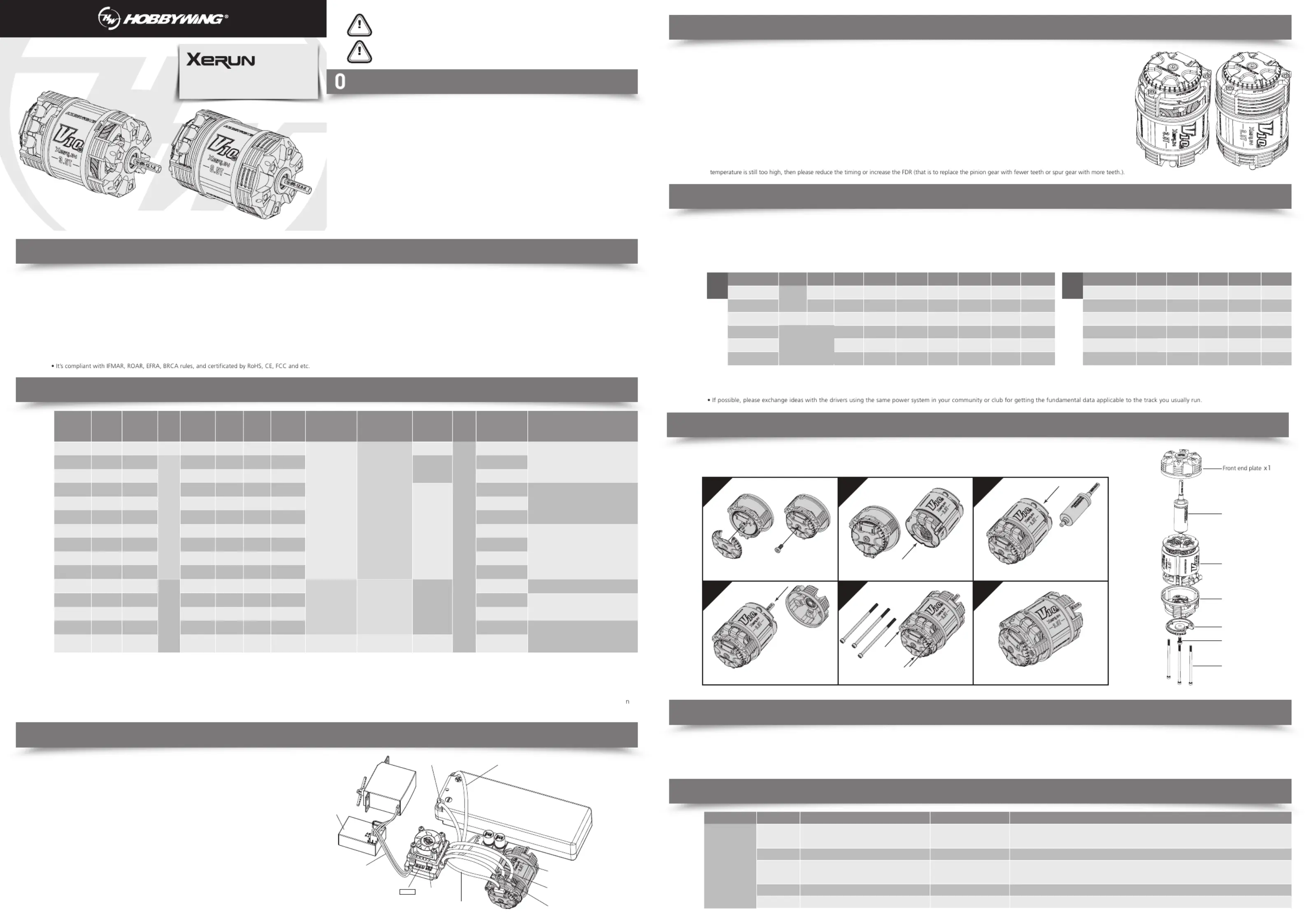
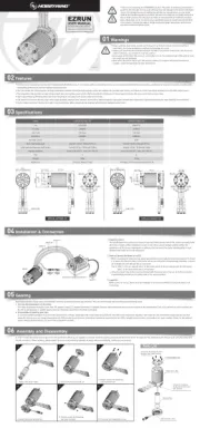
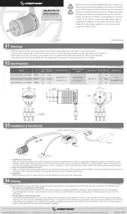
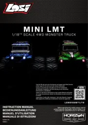
Xerun V10 G3
| Mærke: | Hobbywing |
| Kategori: | Radiostyret legetøj |
| Model: | Xerun V10 G3 |
| Vægt: | 161 g |
| Produktfarve: | Sort |
| Motortype: | Børsteløs motor |
| Motoreffekt: | 346 W |
| Produkttype: | Motor |
| Impedens: | 0.0074 ohm (Ω) |
| Normal brug: | Car, Truck |
| Kapabilitet: | 1/10th Drift, 2WD Off-road Racing |
| Mærke kompatibilitet: | Hobbywing |
| Strøm (maks.): | 100 A |
| Elektronisk hastighedskontrol (pr. ESC) type: | Børstefri |
| Motor hastighedskonstant (KV): | 4420 RPM/V |
| Batteri eliminator kredsløb (BEC) kontinuerlig strøm: | 3.3 A |
| Motor modstand: | 0.0074 ohm (Ω) |
Har du brug for hjælp?
Hvis du har brug for hjælp til Hobbywing Xerun V10 G3 stil et spørgsmål nedenfor, og andre brugere vil svare dig
Radiostyret legetøj Hobbywing Manualer

29 September 2025
28 September 2025
28 September 2025
18 August 2025
17 Juli 2025
9 Juli 2025
8 Juli 2025
29 Marts 2025
29 Marts 2025
28 Marts 2025
Radiostyret legetøj Manualer
- Multiplex
- Sharper Image
- Losi
- Maginon
- Silvergear
- Hobby Zone
- Ninco
- Joysway
- ACME
- Flyzone
- Traxxas
- Kyosho
- Velleman
- MJX
- FMS
Nyeste Radiostyret legetøj Manualer
10 November 2025

29 Oktober 2025
27 Oktober 2025
26 Oktober 2025
27 September 2025
27 September 2025
23 September 2025
15 September 2025
14 September 2025
14 September 2025