Explanation for LED Status
This is an extremely powerful brushless motor system. For your safety and the safety of those around you, we strongly recommend removing the pinion gear attached to the motor before
performing calibration and programming functions with this system. It is also advisable to keep the wheels in the air when you turn on the ESC.
• 2 select-to-use profiles applicable to RC car racing.
• Adjustable PWM & brake frequencies allows users to precisely regulate the driving & braking forces (of the motors).
• Softening function (innovative by HOBBYWING) for power delivery tuning and better driving efficiency.
• Multiple protections: low-voltage cutoff protection, ESC and motor thermal protection, fail safe (throttle signal loss protection), reverse polarity protection.
• The data recording function utilizes the OTA Bluetooth module to view various running data of the power system in the HW LINK App on mobile phones, making it easier for drivers to analyze the operation of the power
• Firmware upgrade via Hobbywing LCD Program Box Pro/G2 or OTA Programmer (item sold separately).
It is effective within the whole throttle range; it directly affects the car speed on straightaway and winding course. The ESC adjusts the timing dynamically according to the setting of the "Boost Timing Activation".
The Boost Timing is not constant but variable.
4B. Boost Timing Activation
In RPM mode, it is associated with the 4C and 4D parameter items. The actual Boost Timing is 0 when the RPM is lower than the Boost Start RPM. The Boost Timing changes as per the RPM when the RPM change is
between the Boost Start RPM and the Boost End RPM. When the RPM is higher than the Boost End RPM, the actual Boost Timing is the value you had previously set.
In Auto mode, the ESC adjusts the Boost Timing dynamically as per the throttle amount. Only at full throttle, the actual Boost Timing is the value you had previously set.
This item defines the RPM at which Boost Timing is activated. For example, when the Boost Start RPM is set to 5000, the ESC will activate the corresponding Boost Timing when the RPM goes above 5000. The specific
value is determined by the Boost Timing and the Boost End RPM you had previously set.
This item defines the RPM at which Boost Timing (you specifically set) is applied. For example, when Boost Timing is set to 10 degrees and the Boost End RPM to 15000, the ESC will activate the Boost Timing of 10
degrees when the RPM goes above 15000. The ESC will adjust the Boost Timing accordingly as per the actual RPM when the RPM goes below 15000.
This item is adjustable from 0 degree to 48 degrees, the corresponding turbo timing (you set) will initiate at full throttle. It’s usually activated on long straightaway and makes the motor unleash its maximum potential.
When “TURBO DELAY” is set to “INSTANT”, the Turbo Timing will be activated right after the throttle trigger is moved to the full throttle position. When other value(s) is applied, you will need to hold the throttle
trigger at the full throttle position (as you set) till the Turbo Timing initiates.
This item is used to define the “speed” at which Turbo Timing is released when the trigger condition is met. For example, “3 degs/0.1sec” refers to the Turbo Timing of 3 degrees that will be released in 0.1 second.
Both the acceleration and heat is higher when the “Turbo increase rate” is of a larger value.
After the Turbo Timing is activated and the trigger condition turns to not be met (i.e. vehicle slows down at the end of the straightaway and gets into a corner, full throttle turns to partial throttle, the trigger condition
for Turbo Timing turns to be not met), if you disable all the Turbo Timing in a moment, an obvious slow-down like braking will be felt and result in poor control. If the ESC can disable the Turbo
Timing at some “speed”, the slow-down will be linear and the control will be improved.
Warning Boost Timing & Turbo Timing can effectively improve the motor efficiency; they are usually used in competitions. Please take some time to read this manual and then set these two items !
carefully, monitor the ESC & motor temperatures when you have a trial run and then adjust the Timing and FDR accordingly as aggressive Timings and FDR may cause your ESC or motor to
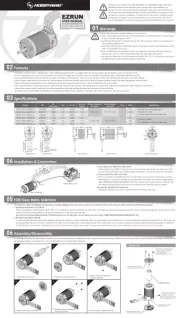
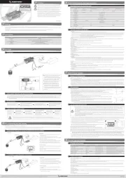
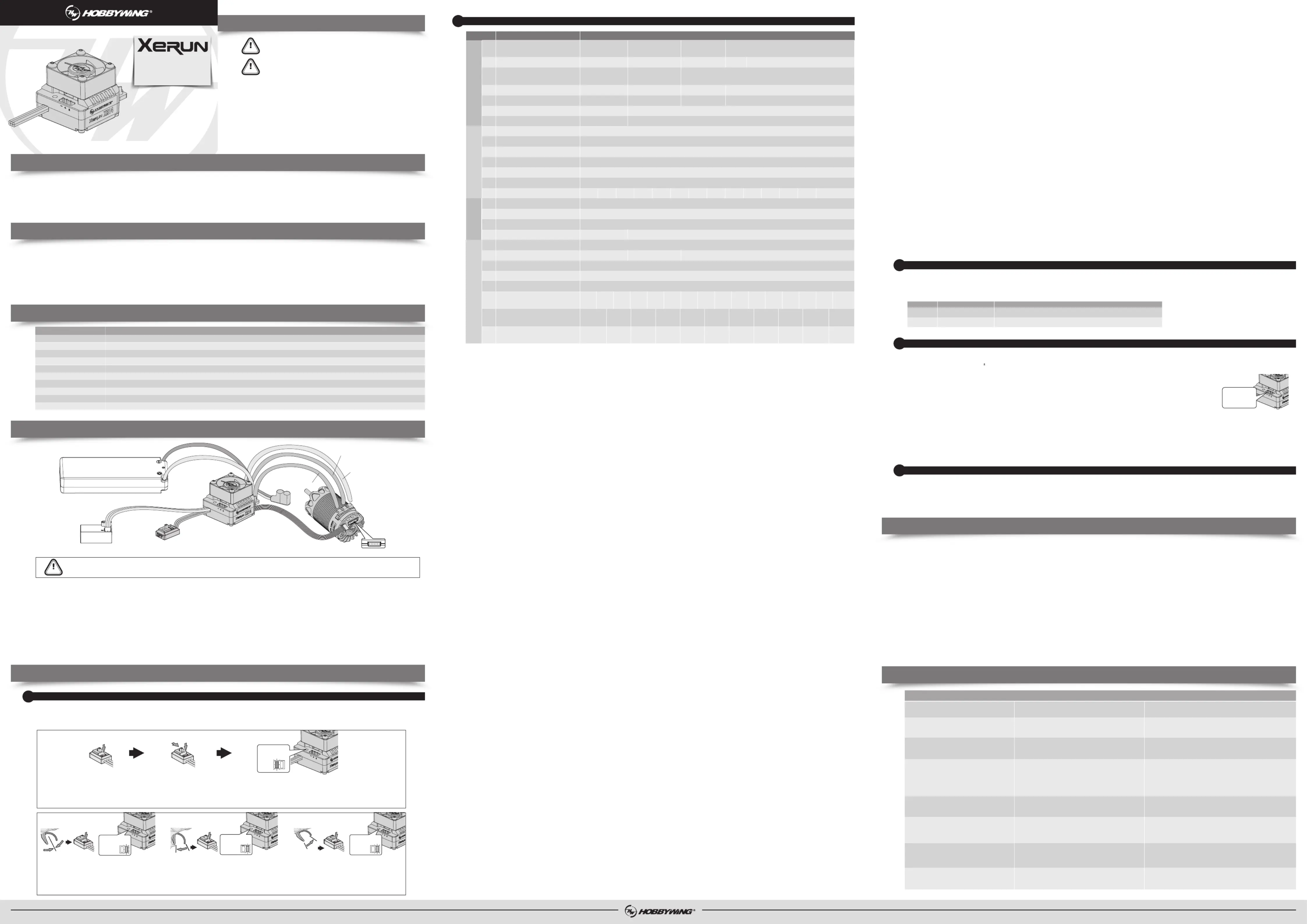
Sensored motor connection MUST connect A from the ESC to A on the motor, B to B, and C to C, with the sensor wire connected any variation of the motor to ESC connections may cause damage.
Note:If the motor direction is reversed, change the parameter item “Motor Rotation” to change the motor direction.
The throttle control cable on the ESC has to be plugged into the throttle (TH) channel on the receiver. The throttle control cable has an output voltage of ESC to the receiver and steering servo, no separate battery can
be connected to the receiver. Otherwise, your ESC may be damaged. If additional power is required, disconnect the red wire on the throttle plug from the ESC.
Proper polarity is essential. Please ensure positive (+) connects to positive (+), and negative (-) connects to negative (-) when plugging in the battery! Please note, this esc has reverse polarity protection, so reverse
connection will not damage the esc, but standard conventional external capacitor pack will be damaged.
1. During the Start-up Process
• The RED LED turns on solid indicating the ESC doesn’t detect any throttle signal or the throttle trigger is at the neutral position.
• The GREEN LED flashes rapidly indicating the neutral throttle value stored on your ESC may be different from the current value stored on the transmitter. When this happens, re-calibrate the throttle range.
• The RED LED turns on solid when the throttle trigger is in the throttle neutral zone. The RED LED will blink slowly to suitable for zero-timing/Blinky racing rules if the total value of Boost Timing and Turbo timing is 0,
and the Softening value is also set to 0 at the same time..
• The GREEN LED blinks when your vehicle runs forward. The GREEN LED turns solid when pulling the throttle trigger to the full (100%) throttle endpoint.
• The GREEN LED blinks when you brake your vehicle. The GREEN LED turns solid when pushing the throttle trigger to the full brake endpoint and setting the “maximum brake force” to 100%.
• The GREEN LED blinks when you reverse your vehicle. The GREEN LED turns solid when pushing the throttle trigger to the full brake endpoint and setting the “reverse force” to 100%.
3. When Some Protection is Activated
• The RED LED flashes a short, single flash and repeats “ , , ” indicating the low voltage cutoff protection is activated.☆ ☆ ☆
• The GREEN LED flashes a short, single flash and repeats “ , , ” indicating the ESC thermal protection is activated.☆ ☆ ☆
• The GREEN LED flashes a short, double flash and repeats “ , , ” indicating the motor thermal protection is activated.☆☆ ☆☆ ☆☆
• The RED & GREEN LEDS flash a short, single flash and repeats at the same time indicating the drive mode has been automatically switched to sensorless mode from senored mode because of abnormal
sensor signal when pairing the ESC with a sensored motor.
In order to make one firmware applicable to all different racing conditions, there are two “easy-to-select” preset modes (as shown below). Users are able to change the settings of the modes provided (and rename those
modes) as per the control feel, track, and etc.
Suitable for 1/14 on-road racing
Suitable for 1/14 off-road racing
Preset Modes for Different Racing:
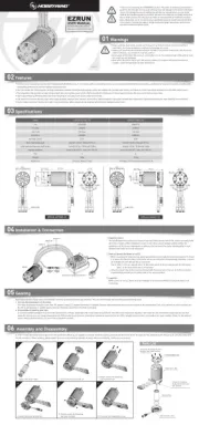
Sensored/Sensorless Brushless Motors
1/14 Scale Racing, 1/12&1/10 Light load vehicles with zero-timing(blinky) mode
KV 6000 or 8.5T 2848(380)&3650(540)size motor≤ ≥
6V/7.4V @ 4A(Switch-mode)
Powered by the BEC voltage
35.2(L) x 31.3(W) x 28.5(H)mm(w/Fan)
SHENZHEN HOBBYWING TECHNOLOGY Co., LTD. · 101-402 Building 4, Yasen Chuangxin Hi-tech Industrial Park, 8 Chengxin Road, Baolong Industrial Town, Longgang District, Shenzhen, China. October 25, 2024
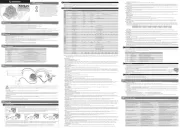
1. Program your ESC with a Multifunction LCD Program Box Pro
Connect the interface marked with "- + " on the esc to the interface marked with "ESC" on the program box using a separate programming cable(a cable with JR plugs at both ends included in the program box
packaging), then connect the esc to the battery and turn it on. Click on Parameter Settings to set the esc.【 】
2. Using the OTA Programmer for parameter settings
Insert the programming cable of the OTA Programmer into the programming interface of the esc, and use your phone to install the HW Link APP to set the esc.
3. Read the running data of esc
1) Click on the Data record on the homepage of the LCD box pro to read the five extreme values of the highest temperature of the esc, the highest temperature of the 【 】
motor, the maximum current, the lowest voltage of the battery, and the highest rpm of the motor during the operation of the esc.
2) By using the OTA Bluetooth module, you can view the five extreme values recorded above, real-time data, and historical data (curve chart) under the Data Log menu in 【 】
the HW LINK App on your phone.
• Restore the default values with a Multifunction LCD Program Box Pro
After connecting the program box to the ESC, Click on Parameter Settings and select the Reset Parameters to restore the factory settings.【 】 【 】
• Restore the default values with a OTA Programmer (& HW Link App)
After connecting the OTA Programmer to the ESC, open the HOBBYWING HW Link App on your smart phone, select “Parameters” followed by “Factory Reset” to reset the ESC.
Trouble SolutionsPossible Causes
No power was supplied to the ESC.
The throttle cable of the esc is connected incorrectly
or the throttle is not at the neutral position.
The default/popular motor rotation direction does not match
1. The receiver was influenced by some foreign interference;
2. The ESC entered the LVC protection;
3. The ESC entered the thermal shutdown protection.
1. The throttle neutral position on your transmitter
was actually in the braking zone;
2. Set the “Running Mode” improperly;
1. The (ESC-to-motor) wiring order was incorrect
2. Some soldering between the motor and the ESC was not good;
3. The ESC was damaged (some MOSFETS were burnt).
Check if all ESC & battery connectors have been well soldered or
1. Plug the throttle cable into the throttle channel (CH2) by referring to
relevant mark shown on your receiver.
2. Calibrate the esc and radio.
Adjust the parameter "Motor Rotation".
1. Check all devices and try to find out all possible causes, and check the
transmitter’s battery voltage;
2. The RED LED keeps flashing indicating the LVC protection is activated,
please replace your pack;
3. The Green LED keeps flashing indicating the thermal protection is
activated, please let your ESC cool down before using it again.
1. Recalibrate the throttle neutral position;
2. Set the “Running Mode” to “Fwd/Rev with Brk “;
3. Contact the distributor for repair or other customer service.
1. Check the wiring order;
2. Check all soldering points, please re-solder if necessary;
3. Contact the distributor for repair or other customer service.
1. Change another pack with great discharging capability;
2. Change a low-speed motor, or increase the FDR;
3. Set the Throttle Rate Control to a low level.
1. Check if the sensor cable is loose or poor contact issue exists;
2. Hall sensor inside the motor or the ESC is damaged.
After power on, the RED LED flashes
and the motor does not work.
The vehicle is going in the reversed direction
when the forward throttle is applied.
The ESC was unable to start the status LED, the
motor, after it was powered on.
The motor stuttered but couldn’t start.
The vehicle could run forward (and brake),
The motor got stuck or stopped when increasing
the throttle during the starting-up process.
The RED & GREEN LEDS on the ESC flashed rapidly
at the same time when the throttle trigger was at
The motor suddenly stopped or significantly
reduced the output in operation.
1. Poor discharging capability of the pack;
2. The RPM of the motor was too high, or the FDR
3. The Throttle Rate Control is set too high.
(When pairing with a sensored motor) the ESC
automatically switched to sensorless mode
when it detected incorrect signal from Hall sensor.
Thank you for purchasing this HOBBYWING product! Please read this instruction
manual carefully before use, once you use the product, it is understood that you
have read and agreed with all the content. Brushless power systems can be very
dangerous and any improper use may cause personal injury and damage to the
product and related devices, so please strictly follow the instruction during
installation and use. Because we have no control over the use, installation, or
maintenance of this product, no liability may be assumed for any damages or losses
resulting from the use of the product. We do not assume responsibility for any
losses caused by unauthorized modifications to our product. We have the right to
modify our product design, appearance, features and usage requirements without
notification. We, HOBBYWING, are only responsible for our product cost and
nothing else as result of using our product. With the possible differences between
the two version of the manual, for users in mainland China, please take the
Chinese version as standard; for users in other regions, please take the English
Brushless Electronic Speed Controller
Option 1: Forward with Brake
Racing mode. It has only forward and brake functions.
Option 2: Forward/ Reverse with Brake
This option is known to be the “training” mode with “Forward/ Reverse with Brake” functions. The vehicle only brakes on the first time you push the throttle trigger to the reverse/brake position.If the motor stops
when the throttle trigger return to the neutral position and then re-push the trigger to reverse position, the vehicle will reverse, if the motor does not completely stop, then your vehicle won’t reverse but still brake, you
need to return the throttle trigger to the neutral position and push it to reverse again.This method is for preventing vehicle from being accidentally reversed.
Option 3: Forward and Reverse
The motor will reverse immediately when the throttle trigger is pushed to reverse position.This mode is generally used in special vehicles.
The reverse force of the value will determine its speed. For the safety of your vehicle, we recommend using a low amount.
Sets the voltage at which the ESC lowers or removes power to the motor in order to either keep the battery at a safe minimum voltage (for LiPo batteries). The ESC monitors the battery voltage all the time, it will
reduce the power and then cut off the output about 40 seconds later when the voltage goes below the cutoff threshold. The RED LED will flash a short, single flash that repeats ( , , ) to indicate the low-voltage ☆ ☆ ☆
cutoff protection is activated. Please set the “Cutoff Voltage” to “Disabled” or customize this item if you are using NiMH batteries.
The ESC does not cut the power off due to low voltage. We do not recommend using this option when you use any LiPo battery as you will irreversibly damage the product. You need to select this option when you are
The ESC calculates the corresponding cutoff voltage for the battery shall be 7.0V(2S LiPo).
The customized cutoff threshold is a voltage for the whole battery pack (adjustable from 3.0V to 7.4V).
1D. ESC Thermal Protection
After enabling this function, when the temperature of the ESC reaches the set value, it will reduce the power and then cut off the output about 40 seconds later. The Green LED will flash a short, single flash that repeats
( , , ) to indicate the over-heat protection is activated.☆☆☆
Warning! Please do not disable this function unless you’re in a competition. Otherwise the high temperature may damage your ESC and even your motor.
1E Motor Thermal Protection
After enabling this function, when the temperature of the motor reaches the set value, it will reduce the power and then cut off the output about 40 seconds later. The Green LED will flash a short, double flash that
repeats ( , , ) to indicate the over-heat protection is activated.☆☆ ☆☆ ☆☆
Warning! Please do not disable this function unless you’re in a competition. Otherwise the high temperature may damage your motor and even your ESC. For non-Hobbywing motor, the ESC may get
this protection activated too early/late because of the different temperature sensor inside the motor. In this case, please disable this function and monitor the motor temperature manually.
It supports 6.0V/7.4V adjustable. Set a reasonable value according to the working voltage of the servo.
1G. Motor Rotation/Direction
Used to set the rotation direction of the motor. Due to differences in chassis frame structure, it is possible for the car to reverse when the throttle is applied to forward, in this case, you can solve it by adjusting this item.
2A. Throttle Rate Control
This item is used to control the throttle response. The higher the throttle rate, the more aggressive the throttle will be applied. A suitable rate can help driver to control the vehicle properly during the starting-up process.
This parameter adjusts the range of the throttle neutral area to suit different transmitters and driver habits. If the neutral position of the transmitter is unstable, causing the car to move slowly forward or backward, or
have difficulties calibrating the neutral range, the setting can be raised to correct the issue.
2C. Initial Throttle Force
It also called as minimum throttle force. You can set it according to wheel tire and traction. If the ground is slippery, please set a small throttle force. Some motors have strong cogging effect with lower FDR, if there is any
cogging with very light throttle input, you can try to increase the initial throttle force.
This function allows the motor to naturally and smoothly reduce rpm/speed, and the vehicle will not experience sudden deceleration during the throttle release process. The higher the value, the stronger the "coasting"
When a vehicle has a larger final drive ratio, the tendency of having a “drag” feel is higher. The “COAST” technology is to allow the car to roll (coast) even when the final drive ratio is high. The Coast function brings
better and smoother control feeling to racers. Some drivers will refer to this to the traditional brushed motors.
Note: The Coast setting will not work if the drag brake is not set to 0%.
The acceleration will be more aggressive at the initial stage when the drive frequency is low; a higher drive frequency is smoother but this will create more heat to the ESC.
It allows users to fine-tune the bottom end, change the driving feel, and maximize the driving efficiency at different track conditions. The higher the "Softening Value ", the softer the bottom end. Sometimes drivers
may feel the power of the bottom end is too aggressive. Little throttle input usually brings too much power to the car and make it hard to control at the corners, this is HOBBYWING's solution to help bottom end traction.
It's the range to which "Softening Value” starts and ends. If set to 30% then the softening range will be from 0 throttle to 30% throttle.
It is the braking power produced when releasing from full speed to neutral position. This is to simulate the slight braking effect of a neutral brushed motor while coasting. It’s not recommended for buggy and monster
truck. (Attention! Drag brake will consume more power and heat will be increased, apply it cautiously.)
This ESC provides proportional braking function; the braking effect is decided by the position of the throttle trigger. It sets the percentage of available braking power when full brake is applied. Large amount will
shorten the braking time but it may damage your pinion and spur.
This parameter is used to control the response of the brake. The higher the setting value, the faster the brake. A suitable rate can aid the driver to brake his vehicle correctly. Generally, you can set it to a high value to
have a quick brake response.
The brake force will be larger if the frequency is low; you will get a smoother brake force when the value is higher. Please choose the frequencies as per the actual test results of your vehicles.
Parameter ValuesSection Item
• To avoid short circuits, ensure that all wires and connections are well insulated before connecting the ESC to related devices.
• Ensure all devices in the system are connected correctly to prevent any damage to the system.
• Read the manuals of all the items being used in the build. Ensure gearing,setup, and overall install is correct and reasonable.
• Stop usage if the casing of the ESC exceeds 90 / 194 as this may cause damage to both the ESC and motor. Hobbywing recommends setting the “ESC Thermal Protection” to 105 / 221 (this refers to the internal ℃ ℉ ℃ ℉
• The battery must be disconnected after use. There is a small draw even when the system is off, and will eventually fully drain the battery. This may cause damage to the ESC, and will NOT BE COVERED UNDER WARRANTY.
Forward and ReverseForward/ Reverse with Brake
Running Mode Forward with Brake
3.0-7.4V Adjustable (Step: 0.1V)Auto (3.5V/Cell)
ESC Thermal Protection Disabled
Motor Thermal Protection Disabled
3%-10% Adjustable (Step: 1%)2B
1-15 Adjustable (Step: 1)2C
1-30 Adjustable (Step: 1)
0-15% Adjustable (Step: 1%)
0-30°Adjustable (Step: 1°)
0% 25% 30% 35% 40% 45% 50% 55% 60% 65% 70% 75%
0-48°Adjustable (Step: 1°)
500-35000RPM (Step: 500RPM)
0-48°Adjustable (Step: 1°)
3000-60000RPM (Step: 500RPM)
1deg/0.1s 2deg/0.1s 3deg/0.1s 5deg/0.1s 8deg/0.1s 12deg/0.1s 16deg/0.1s 20deg/0.1s 25deg/0.1s 30deg/0.1s
1deg/0.1s 2deg/0.1s 3deg/0.1s 5deg/0.1s 8deg/0.1s 12deg/0.1s 16deg/0.1s 20deg/0.1s 25deg/0.1s 30deg/0.1s
0.15s 0.2s 0.25s 0.3s 0.35s 0.4s 0.45s 0.5s 0.6s 0.7s 0.8s 0.9s 1.0s
0%-100% Adjustable (Step: 1%)
0%-100% Adjustable (Step: 1%)
4. Upgrade of firmware for esc
1) Using the LCD box pro or OTA programmer, download and install the HW LINK App on your phone,click on the Firmware Update button on the APP homepage to upgrade the firmware of the esc.【 】
2) Connect to the computer through the LCD box pro, download and install Hobbywing USB LINK software on the computer, and use this software to upgrade the firmware for esc.
Electronic Speed Controller
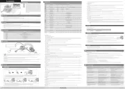
With the throttle trigger in the neutral
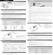
3. Set the neutral point, the full throttle endpoint and the full brake endpoint.
1) Leave the throttle trigger at the neutral position, press the SET button, the GREEN LED dies out and the GREEN LED flashes once and the motor beeps 1 time to store the neutral position.
2) Pull the throttle trigger to the full throttle, press the SET button, the GREEN LED flashes twice and the motor beeps 2 times to store the full throttle position.
3) Push the throttle trigger to the full brake, press the SET button, the GREEN LED flashes 3 times and the motor beeps 3 times to store the full brake position.
4. The motor can work normally after the throttle range calibration is complete.
Move the throttle trigger to the full throttle.
Move the throttle trigger to the full brake.
The calibration must be done on the first use of the ESC, or if a new radio or receiver is installed otherwise the ESC cannot work correctly. ,
We strongly recommend to activate the “Fail Safe” function of the transmitter and set no signal protection for throttle channel of transmitter (F/S) to “OFF” or set its value to the “Neutral
Position” to ensure the motor can be stopped when there is no signal received from the transmitter. The throttle calibration steps is as follows:
1. Turn on the transmitter, set parameters on the throttle channel like “D/R”, “EPA” and “ATL” to 100% (for transmitter without LCD, please turn the knob to the maximum) and the
throttle “TRIM” to 0 (for transmitter without LCD, please turn the corresponding knob to the neutral position). This step can be skipped if the radio's settings are default!
2. Turn off the ESC. Hold the SET button and turn on the ESC, the RED LED on the ESC starts to flash (the motor beeps at the same time), and then release the SET button.
Note : Beeps from the motor may be low sometimes, and you can check the LED status instead.