Thank you for your purchase.
Please read the following statement carefully before use.
Once used, it is considered to be an acceptance of all the contents.
Please follow the manual instructions carefully during the installation.
Modification may result in personal injury and product damage.
We reserve the rights to update the design and performance of the product
Recommend Take-off Weight: 25-27kg/rotor(54V, Sea Level)
Recommended Battery: 12-14S LiPo(Max 61V)
Maximum Thrust: 53kg+(54V, Sea Level)
Operating Temperature: -20 -50℃ ℃
Mounting Arm Tube Outer Diameter: 50mm
Total Weight: 4257g( INC. prop)
Support throttle Frequency: 50-500Hz
Continuous Current: 80A (Non-hermetic Ambient Temperature ) ≤60℃
Maximum Current.: 200A (Non-hermetic Ambient Temperature ) ≤60℃
Recommended Battery: 12-14S LiPo
Throttle Pulse Width.: 1050-1950µs
Diameter Pitch: 56*20 inch
Single propeller weight: 292g
Weight (INC. adapter): 805g
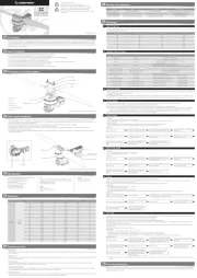
Description of light color status
Propeller Throttle (%) Thrust (g) Ampere (A) Power (W) RPM(r/min)
Flashing of LED Meaning Solution
Replace the battery (Voltage below 81V)
Replace the battery (Voltage higher 24V)
Check the motor for foreign objects and check the propeller,then power on again
• Contact after-sales service
• Check connection between signal line to the flight controller
• Check whether the remote controller and flight controller are turned on
• Check the resistance of the black and white wires, if there is a short circuit, contact the after-sales service
This problem occurs during the rotation of the motor. Please check the aircraft battery and circuit. There is a short circuit on the circuit.
Cool down the power system and power on again
Cool down the power system and power on again
• Restart after the throttle is reset to zero
• Please check if there is any foreign matter in the motor, remove the foreign matter before starting
• • Please check whether the motor circuit is intact Contact after sales service
• • Please check whether the motor is in good condition Contact after sales service
• • Please check whether the motor is in good condition Contact after sales service
• • Re-power on to return to normal Contact after sales service
• • Re-power on to return to normal Contact after sales service
• • Re-power on to return to normal Contact after sales service
Throttle not reset to zero
Mosfet overheated (Over 110℃)
Capacitor overheated Over 110( ℃)
Phase A operational amplifier is abnormal
Phase B operational amplifier is abnormal
Phase C operational amplifier is abnormal
Single long flash + Single short flash
Single long flash + 2 Short flash
Single long flash + 3 Short flashes
Single long flash + 4 Short flashes
2 long flashes + Single short flash
2 long flashes + 2 Short flash
2 long flashes + 3 Short flash
2 long flashes + 4 Short flash
*Not: The picture is only for reference, please make the object as the standard.
The COMBO-XRotor-X13 brushless power system is a plant protection power system that adapts to a single-rotor load of 25-27kg/rotor. The maximum thrust of a single-rotor is 53kg+; it is suitable for
a 50mm carbon fiber tube arm; the overall waterproof level is IPX6, and it is resistant to rain, rain pesticides, salt spray, high temperature, dust, impact, mud and sand resistance; the ESC uses FOC
vector control, based on PMSM system algorithm optimization; the system has digital throttle and analog throttle, which can make the flight more stable; the system has power-on automatic detection,
power-on voltage abnormal protection, over-current protection, stall protection and other protection functions; use CAN communication, with real-time data transmission; built-in fault storage
function, and records fault data.
• When use it please keep away from crowd, high voltage cable and obstacles and conform to safety regulations.
• Never approach to the high-speed rotating propeller & motor to avoid being injured by propeller.
• Check all the components conditions before use. If there is any damaged component, please contact after-sale service for replacement.
• Check if the mounting screws, and all connecting parts before flight.
• Always make sure the motor is horizontal before flight.
• The X13 power system is connected to a circular tube arm with a diameter of 50mm.
• The color of the power system navigation light can be selected. After removing the light housing, you can select the desired color by flipping the dial switch.
• The CAN function can only be used when the flight controller has a CAN Channel.
• This function can be realized only when the flight controller has a CAN channel.
• There is no digital throttle for serial communication. Serial communication is optional for this power system.
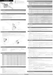
Power system installation
please specify how many screws. fastening screw
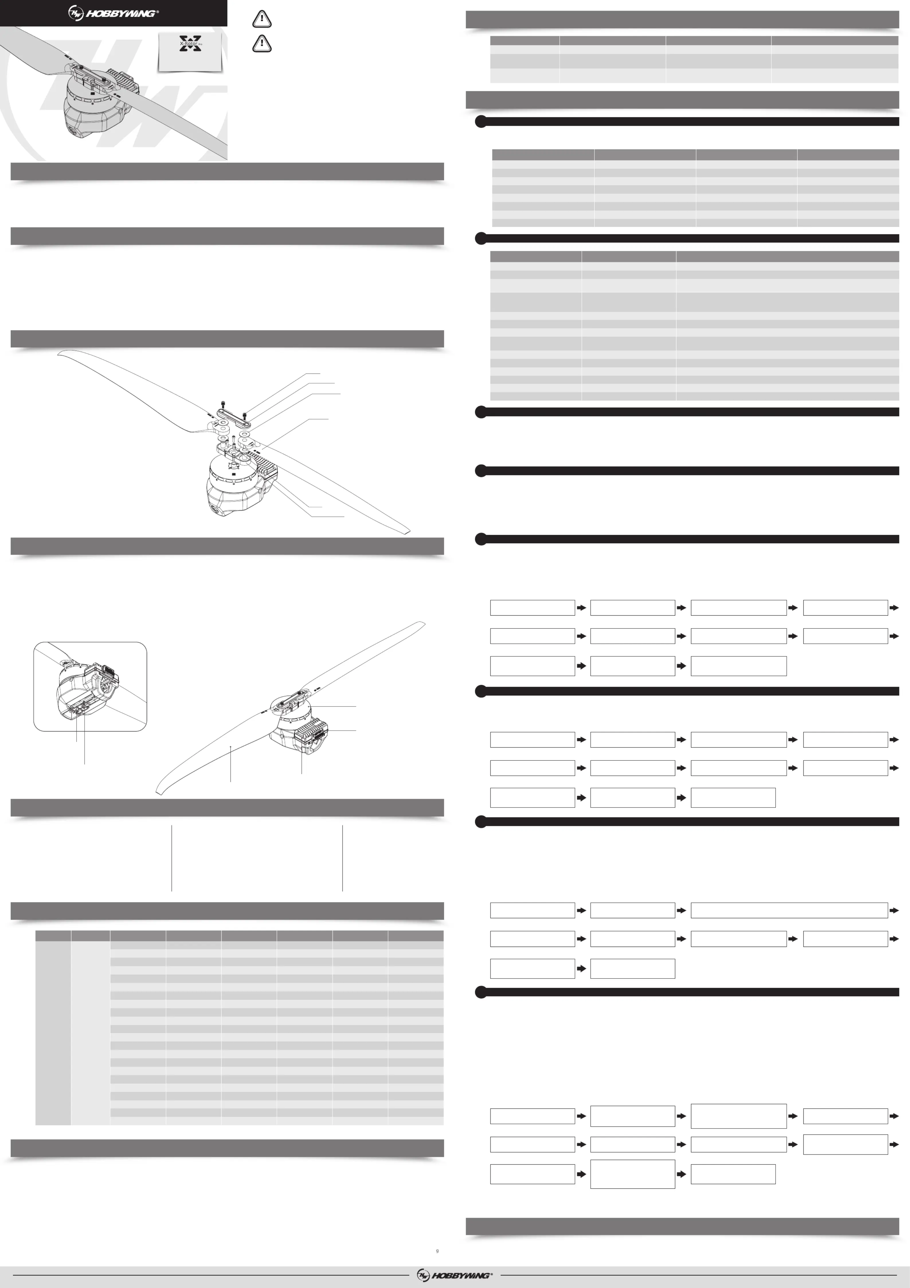
Components of the Power System
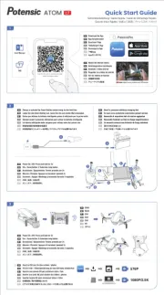
• The whole power system has been assembled before leaves the factory. Unpack and take out the power system to install on the rack agricultural as per the rotation direction of motor.
• The yellow, gray and green cables are the data output. Upgrade signal wire (ESC system is upgradable) and digital throttle using the Hobbywing CAN protocol. The yellow wire is ground wire, the
gray wire is CAN-High( CH), and the green wire is CAN-Low( CL).
• The optional serial communication power system. Yellow, red and green cables are the data output and update signal line (the ESC system can be updated).
• The black and white is the PWM throttle wire, the black wire is ground wire, and the white wire is signal wire.
• The data signal line outputs in real time; the input and output throttle, motor speed, bus current, phase current, bus voltage, capacitor temperature, Mosfet temperature and other data.
• The throttle pulse width was fixed at 1050~1950µs.
• The CAN digital throttle needs to be adapted separately by the flight controller and the Hobbywing CAN protocol. Please obtain the protocol from Hobbywing sales, after-sales service, agents,
flight control manufacturers, etc.
*Not: The picture is only for reference, please make the object as the standard.
When the power is connected normally, the ESC will first start the self-test. If the self-test is successful, it will run normally after beeping. If the self-test fails, it will not start and the flashing light will
When the ESC detects that the motor is locked, the ESC will completely turn off the output and will not restart the motor. At this time, it is necessary to power cycle to clear the error and restart the
ESC to restore power output.
When it detects that the instantaneous current abnormality reaches close to 320A, the ESC will restart immediately, and the output will be turned off if the number of detections reaches 6
consecutive times. After the motor stops, it will return to normal after power on again.
• Throttle signal loss protection:
When the ESC detects that the throttle remote control signal is lost for more than 0.25 seconds, it will immediately turn off the output to avoid greater losses caused by the continued high-speed
rotation of the propeller. After the signal is restored, the ESC will immediately restore the corresponding power output.
• Temperature protection:
This power system has no temperature protection, and will only send out an alarm when the temperature of the ESC is higher than 110°C. The flashing lights will be 1 long and 3 short, and 1 lon
and 4 short. When the temperature exceeds 130 degrees, the ESC may be burnt. Upon seeing the prompt, please land immediately.
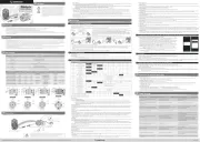
Use a tool to take out the M3×8 screws that fasten the led cover, and set the switches according to the corresponding light color below (factory default green). After the setting the switches, assemble
and fasten the led cover.
• Use the appropriate tools to take out the two propeller fastening screws and replace them with new propellers. If you need to replace the propeller clips, continue to take out the fastening screws
and replace the whole set of propeller clips and propellers.
• Installing the propeller clip blades
Firstl, install the bottom cover on the motor, followed by the propeller blades, propeller gaskets, upper cover (propeller clips) and the final screws in order; pay attention to the installation of the
After clamping, the propeller should rotate freely, and make sure that the propeller clamp and the motor fastening screw are tightened and thread locker is used at the same time.
There are two ways to update the firmware: online update via a computer or using flight control pass through. The process using the flight controller pass through are as follows.
This function uses DataLink data box, special DataLink software for upgrade package, and USB data cable.
DataLink data box version requirements, LINK-01.2.14-C or higher version, LINK-01.2.09-U or higher version; DataLink software contact Hobbywing to obtain.
Note: Please ensure that the computer has already installed the Microsoft Visual C++ 2013 before or later using. An upgrade package contains only one program for each ESC. For other programs,
please obtain a new upgrade package. For additional details, please refer to the DataLink user manual. The upgrade package can be obtained at the place of purchase; Hobbywing official
website, dealers, Hobbywing sales, Hobbywing, and after-sales service. The FOC ESC will not support any other firmware, and can only be updated to the official firmware.
Note: It can only be upgraded from the existing system. Software and hardware cannot be upgraded together.
Connect the computer and the DataLink data box with a USB cable;
ESC---->DataLink data box "yellow red green"---->"- D", any channel from D1-D8 is acceptable, and it is recommended to use D1 channel first.□
It can be obtained at the place of purchase; Hobbywing official website, dealers, Hobbywing sales, and Hobbywing after-sales service.
Note: It can only be upgraded from the existing program, and software and hardware cannot be upgraded together.
Run the DataLink software.
Click the "USB-serial port" button in the upper
right corner to enter the serial port page.
Click "Fault Analysis" to enter the page. Power on the ESC.
Select the serial port number, the default
baud rate, click "Open Serial Port" to
connect the ESC to the computer.
Connect the USB cable to the data box, connect
the ESC to the data box, check whether the
firmware of DataLink itself matches the ESC.
The serial port uses the version ending with -U, update
the firmware version to LINK-01.2.09-U or later; the
CAN ESC uses the version ending in -C, update the
firmware version to LINK-01.2.14- U or later.
Remove the USB cable and connect the serial
Select a channel, click "Read Fault
Information" to view flight faults.
After checking the fault, save the data as
needed; except for the special case of fault
data, it will be kept in the ESC until the
memory is full, and the oldest data will be
overwritten sequentially.
The equipment is powered off, there is no
sequence of power outages, and the
equipment will not be burned.
The ESC is connected to the data box, and
the data box is connected to the computer.
Enter the CAN parameter adjustment page.
Wait for the bus speed automatic setting
Click "Set ID and Throttle Channel" and
wait for the data to be saved.
Run the DataLink software.
Enter the software page, confirm the software version of DateLink in the type "DataLink", and ensure
that the program version is above LINK-01.2.14-C.
Check the prompt in the upper left corner
to see if the setting is complete.
The equipment is powered off, there is no
sequence of power outages, and the
equipment will not be burned.
In the event that the equipment of the power system is damaged, please contact Hobbywing after-sales customer service immediately. Under the premise of not affecting the performance, make sure
that you can use the Hobbywing power system kit accessories for replacement after contacting the customer service. Users are prohibited from configuring accessories by themselves (such as screws,
propeller clips, propellers) for replacement.
If there is no requirement, the default factory ID of the ESC is 1, the throttle channel is 1, and the bus speed is 500Hz.
This function is only available for CAN communication ESCs, and the serial port does not have this function. This function can communicate with the flight controller to realize digital throttle.
This function requires the additional purchase of DataLink data box.
Before using this function, ensure that the computer system is installed with the Microsoft Visual C++ 2013 software in advance to operate.
ESC---->DataLink data box "yellow gray green"---->"-CH1 CL1";
Connect the data box to the computer via USB.
Please remove the propeller to avoid danger upon changing the ID.
For the same aircraft, different ESC IDs and throttles cannot be the same. ESCs with the same ID will be recognized as one ESC upon using the CAN function.
The ESC has its own fault storage function to store the time during power-on, flight time, and fault time information. This function makes it convenient for flight fault analysis. Please note that this
function only records the data at the time of failure, and not all flight data.
This function requires the use of DataLink data box, serial port assistant, DataLink software, and USB data cable.
Note: DataLink software can be obtained from Hobbywing official website, dealers, Hobbywing sales, and Hobbywing after-sales.
DataLink data box version requirements, LINK-01.2.14-C or later; serial port assistant requirements, USB to TTL; DataLink software requires a fault storage version, which can be obtained from the
official website, WeChat official account or after-sales.
The DataLink box has three power supply methods; USB data cable, serial port assistant, and external power supply cable. You can choose one of the power supply methods, and there is no need to
use multiple power supply methods.
Note: For detailed steps, please refer to the DataLink user manual.
Serial assistant ----> DataLink data box "GND 5V TX RX" ----> "- + RX2 TX2";
CAN communication ESC ----> DataLink data box "yellow gray green" ----> "- CH1 CL1", multiple ESCs can be used in parallel.
Note: Upon using multiple ESCs in parallel, the ID and throttle number must be set differently in order for one ESC to be recognized.
Serial communication ESC---->DataLink data box "yellow red green"---->"- D", any channel of D1-D8 is acceptable, and it is recommended to use D1 channel first.□
Note: This function requires the serial port assistant. Before using it, please ensure that the serial port assistant is in working coditions. If it cannot be used, please replace the serial port assistant and
Run the DataLink software.
Select the "Scan" button first, and then
After the channel on the page is ticked,
select the "Stop" button.
After the hardware and firmware information
In "Available Version", select the desired
firmware and click "Update".
The USB cable is connected to the data box,
and the ESC is connected to the data box.
Click "DataLink" of the software,Check the data
box firmware and update the firmware version to
Click "Uart->ESC(FAST)", the ESC firmware
Wait for the upgrade to complete, if the
upgrade fails, please scan for the upgrade
After the upgrade is complete, please scan
again to confirm that the program is
There is no sequence of power off, and the
equipment will not be burned.
Connect the computer and the DataLink data box with a USB cable;
ESC---->DataLink data box "yellow red green"---->"- D", any channel from D1-D8 is acceptable, and it is recommended to use D1 channel first.□
Run the DataLink software.
Select the "Scan" button first, and then
After the channel on the page is ticked,
select the "Stop" button.
After the hardware and firmware information
In "Available Version", select the desired
firmware and click "Update".
The USB cable is connected to the data box,
and the ESC is connected to the data box.
Click "DataLink" of the software,View data box
firmware, firmware version LINK-01.2.14-C or later.
Click "CAN->ESC(FAST)", ESC firmware
Wait for the upgrade to complete, if the
upgrade fails, please scan for the upgrade
After the upgrade is complete, please scan
again to confirm that the program is
The equipment is powered off, there is no
sequence of power outages, and the equipment
SHENZHEN HOBBYWING TECHNOLOGY Co., LTD. · 101-402 Building 4, Yasen Chuangxin Hi-tech Industrial Park, 8 Chengxin Road, Baolong Industrial Town, Longgang District, Shenzhen, China.
Motor fails to start after power on
Motor fails to start after pown on
The power-on voltage is lower than
Possible causesToneSymptom
“Beep beep beep” rapid monotone
“Beep, Beep, Beep” (2 second for each interval)
“Beep , Beep , Beep” (1 second for each interval)
Throttle is not reset to zero
No throttle signal input on the receiver throttle channel
Battery voltage is too low or too high
Push the throttle to the lowest point or recalibrate the throttle point
Check if transmitter and receiver is normal.
Check if wiring of throttle channel is normal
Replace with a suitable battery