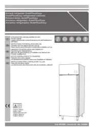
Hoshizaki PT1A-FG-FG Manual
Læs nedenfor 📖 manual på dansk for Hoshizaki PT1A-FG-FG (48 sider) i kategorien Køleskab. Denne guide var nyttig for 11 personer og blev bedømt med 4.4 stjerner i gennemsnit af 6 brugere
Side 1/48

Models
Upright A-Series
Instruction Manual
Issued: 11-21-2019
Revised: 2-6-2020
hoshizakiamerica.com
Steelheart Series
Refrigerated Kitchen Equipment

2
WARNING
Only qualied service technicians should install and service the appliance. To
obtain the name and phone number of your local Hoshizaki Certied Service
Representative, visit www.hoshizaki.com. No installation or service should be
undertaken until the technician has thoroughly read this Instruction Manual.
Likewise, the owner/manager should not proceed to operate the appliance until the
installer has instructed them on its proper operation. Failure to install, operate, and
maintain the appliance in accordance with this manual may adversely affect safety,
performance, component life, and warranty coverage. Proper installation is the
responsibility of the installer. Product failure or property damage due to improper
installation is not covered under warranty.
Hoshizaki provides this manual primarily to assist qualied service technicians in the
installation, maintenance, and service of the appliance.
Should the reader have any questions or concerns which have not been satisfactorily
addressed, please call, send an e-mail message, or write to the Hoshizaki Technical
Support Department for assistance.
Phone: 1-800-233-1940; (770) 487-2331
Fax: 1-800-843-1056; (770) 487-3360
E-mail: techsupport@hoshizaki.com
618 Highway 74 South
Peachtree City, GA 30269
Attn: Hoshizaki Technical Support Department
Web Site: www.hoshizaki.com
NOTE: To expedite assistance, all correspondence/communication MUST include the
following information:
• Model Number
• Serial Number
• Complete and detailed explanation of the problem.

3
CONTENTS
Important Safety Information 4 .................................................................................................
I. Installation Instructions 7 .......................................................................................................
A. Location 7 ........................................................................................................................
B. Checks Before Installation 8 .............................................................................................
C. Setup 9 .............................................................................................................................
D. DT1A-HS Heated Condensate Pan Installation ........................................................... 10
E. Food Cart Ramp (Roll-In/Roll-Thru Appliances) .......................................................... 12
F. Door Reversal .............................................................................................................. 14
1. Full Solid Door Reversal ......................................................................................... 14
2. Half Solid Door Reversal........................................................................................ 17
3. Full Glass Door Reversal 22 .......................................................................................
4. Half Glass Door Reversal 27 ......................................................................................
G. Electrical Connection 33 ..................................................................................................
H. Final Checklist 34 .............................................................................................................
II. Operating Instructions 35 ......................................................................................................
A. Important Notes About Usage 35 ....................................................................................
B. Startup 37 ........................................................................................................................
C. Controls and Adjustments 37 ...........................................................................................
1. Temperature Display ............................................................................................... 37
2. Adjusting the Temperature Setpoint ....................................................................... 38
3. Changing the Temperature Display Scale (°F or °C) 38 .............................................
4. Light Control for Glass Door Models 38 ......................................................................
D. Control Module Buttons and Icons 39 ..............................................................................
E. Defrost 40 .........................................................................................................................
F. Food Storage 41 ...............................................................................................................
G. Alarm Safeties ............................................................................................................. 42
H. Safety Devices 43 ............................................................................................................
I. Cooling Performance 43 ....................................................................................................
J. Cabinet Condensation 43 .................................................................................................
III. Cleaning and Maintenance Instructions 44 ..........................................................................
A. Cleaning 44 ......................................................................................................................
B. Maintenance 45 ................................................................................................................
IV. Preparing the Appliance for Periods of Non-Use 46 ............................................................
V. Disposal 47 ...........................................................................................................................
IMPORTANT
This manual should be read carefully before the appliance is installed and
operated. Read the warnings and guidelines contained in this booklet carefully as
they provide essential information for the continued safe use and maintenance of
the appliance. Retain this booklet for any further reference that may be necessary.

5
WARNING
The appliance should be destined only to
the use for which it has been expressly
conceived. Any other use should be
considered improper and therefore
dangerous. The manufacturer cannot be
held responsible for injury or damage
resulting from improper, incorrect, and
unreasonable use. Failure to install,
operate, and maintain the appliance
in accordance with this manual will
adversely affect safety, performance,
component life, and warranty coverage.
To reduce the risk of death, electric
shock, serious injury, or re, follow
basic precautions including the
following:
• Only qualied service technicians should
install and service the appliance.
• Wear appropriate personal protective
equipment (PPE) when servicing the
appliance.
• The appliance must be installed in
accordance with applicable national, state,
and local codes and regulations.
• Appliance is heavy. Use care when lifting
or positioning. Work in pairs when needed
to prevent injury or damage.
• To reduce the risk of electric shock, do not
touch the plug with damp hands.
• Unplug the appliance before servicing.
• The appliance requires an independent
power supply of proper capacity. See the
nameplate for electrical specications.
Failure to use an independent power
supply of proper capacity can result in a
tripped breaker, blown fuse, damage to
existing wiring, or component failure.
This could lead to heat generation or re.
WARNING, continued
• THE APPLIANCE MUST BE
GROUNDED. The appliance is equipped
with a NEMA5-15 three-prong grounding
plug to reduce the risk of potential
shock hazards. It must be plugged into a
properly grounded, independent 3-prong
wall outlet. If the outlet is a 2-prong outlet,
it is your personal responsibility to have
a qualied electrician replace it with a
properly grounded, independent 3-prong
wall outlet. Do not remove the ground
prong from the power cord and do not use
an adapter plug. Failure to follow these
instructions may result in death, electric
shock, or re.
• Do not use an extension cord.
• Do not use an appliance with a damaged
power cord. The power cord should not be
altered, jerked, bundled, weighed down,
pinched, or tangled. Such actions could
result in electric shock or re. To unplug
the appliance, be sure to pull the plug, not
the cord, and do not jerk the cord.
• The GREEN ground wire in the
factory-installed power cord is connected
to the appliance. If it becomes necessary
to remove or replace the power cord, be
sure to connect the power cord's ground
wire.
• Do not splash, pour, or spray water
directly onto or into the appliance. This
might cause short circuit, electric shock,
corrosion, or failure.
• Do not make any alterations to the
appliance. Alterations could result in
electric shock, injury, re, or damage to
the appliance.
• The appliance is not intended for use by
persons (including children) with reduced
physical, sensory, or mental capabilities,
or lack of experience and knowledge,
unless they have been given supervision
or instruction concerning use of the
appliance by a person responsible for
their safety.

6
WARNING, continued
• Do not put warm or hot foods in the cabinet.
Let them cool rst, or they will raise the
cabinet temperature and could deteriorate
other foods in the cabinet or overload the
appliance.
• Food storage and handling must comply with
applicable codes and regulations.
• All foods should be wrapped in plastic lm
or stored in sealed containers. Otherwise
foods may dry up, pass their smells onto
other foods, cause frost to develop, result in
poor appliance performance, or increase the
likelihood of cross-contamination. Certain
dressings and food ingredients, if not
stored in sealed containers, may accelerate
corrosion of the evaporator, resulting in
failure.
• Do not store items near air outlets.
Otherwise, items may freeze up and
crack or break causing a risk of injury or
contamination of other food.
• Do not place more than 20 lb. (9 kg) on
the top panel. Items must be stable and
secure to prevent items from falling off of the
appliance.
• Care should be used when placing items
on top of the appliance. Do not store liquid
containers or items that could fall through
the louvers on top of the appliance. This
could cause electric shock or re.
NOTICE
• Protect the oor when moving the appliance
to prevent damage to the oor.
• Keep ventilation openings, in the appliance
enclosure or in the built-in structure, clear of
obstruction.
• Do not allow the appliance to bear any
outside weight.
• To prevent deformation or cracks, do not
spray insecticide onto the plastic parts or let
them come into contact with oil.
• To avoid damage to the gasket, use only the
door handle when opening and closing.
WARNING, continued
• Children should be properly supervised
around the appliance.
• Do not climb, stand, or hang on the
appliance or doors or allow children or
animals to do so. Do not climb into the
appliance or allow children or animals to
do so. Death or serious injury could occur
or the appliance could be damaged.
• Be careful not to pinch ngers when
opening and closing the doors or when
handling food pans. Be careful when
opening and closing the doors when
children are in the area.
• Open and close the doors with care.
Opening the doors too quickly or forcefully
may cause injury or damage to the
appliance or surrounding equipment.
• Do not use combustible spray or place
volatile or ammable substances in or
near the appliance. They might catch re.
• Keep the area around the appliance clean.
Dirt, dust, or insects in the appliance
could cause harm to individuals or
damage to the equipment.
• Do not throw anything onto the shelves
or load any single shelf with more than
120lb. (54.5 kg) of product. They might fall
off and cause injury.
• The appliance is designed only for
temporary storage of food. Employ
sanitary methods. Use for any other
purposes (for example, storage of
chemicals or medical supplies such
as vaccine and serum) could cause
deterioration of stored items.
• Do not place any product on the oor of
the cabinet. All product must be placed on
properly installed shelves.
• Do not block air inlets or outlets, otherwise
cooling performance may be reduced.
• Do not tightly pack the cabinet. Allow
some space between items to ensure
good air ow. Also allow space between
items and interior surfaces.

7
I. Installation Instructions
WARNING
• This appliance must be installed in accordance with all applicable national, state,
and local regulations.
• Appliance is heavy. Use care when lifting or positioning. Work in pairs when
needed to prevent injury or damage.
• Do not tilt the appliance more than 45°.
A. Location
WARNING
• This appliance is not intended for outdoor use.
• Normal operating ambient temperature:
– Refrigerators and Solid Door Freezers 45°F to 100°F (7°C to 38°C)
– Glass Door Freezers 45°F to 80°F (7°C to 27°C)
Operation of the appliance, for extended periods, outside of this normal
temperature range may affect appliance performance.
For best operating results:
• The appliance should not be located next to ovens, grills, or other high heat producing
equipment.
• The location should provide a rm and level foundation for the appliance.
• The appliance should not be located in a corrosive environment.
• Minimum Clearance:
Models Side RearTop
Reach-In Refrigerators and Freezers
(Except Roll-In's, Roll-Thru's, Pass-Thru's, and 2-Section Freezers) 0" (0 cm) 0" (0 cm) 3" (8 cm)
Reach-In Refrigerators Roll-In's 0" (0 cm) 10" (25 cm) 0" (0 cm)
Reach-In Refrigerators Roll-Thru's and Pass-Thru's 0" (0 cm) 0" (0 cm) N/A
2-Section Freezers 0" (0 cm) 10" (25 cm) 3" (8 cm)

8
B. Checks Before Installation
WARNING
Refer to the nameplate for electrical specications. The nameplate is located on the
right side wall of the 1 and 2 section cabinet interior and the rear wall of the
3 section cabinet interior. For more electrical connection details, see "I.G. Electrical
Connection." We reserve the right to make specication and design changes
without prior notice.
• Visually inspect the exterior of the shipping package and immediately report any damage
to the carrier. Upon opening the package, any concealed damage should also be
immediately reported to the carrier.
• Remove the shipping carton, tape, and packing material. Remove the protective plastic
lm from the exterior panels on all models and from the interior door panels on solid
door models. If the appliance is exposed to the sun or to heat, remove the lm after the
appliance cools.
• Remove all accessory containers before discarding the packing materials. Dispose of all
packing materials in a proper and environmentally responsible manner.
• Check for missing or damaged accessories.
Nameplate
Fig. 1
Nameplate
Model Shown: R1A-FS
Model Shown: R3A-FS

9
Front of Appliance (standard models)
or Service (control module) Side
(pass-thru models)
Locking Casters
Fig. 2
b) Legs: Optional 6 in. legs available. Attach and tighten the optional adjustable 6 in. legs
to the bottom of the appliance.
WARNING
When using legs, avoid sliding the appliance across the oor after legs are installed.
b) Leveling the Appliance
After installing the casters or optional 6 in. legs, lower the appliance to the oor and
check the level of the appliance.
a) Casters: If the appliance is out of level, follow the instructions and steps found in
HS-3590 provided in the accessories bag. Otherwise, continue to the next section.
NOTICE! Make sure the casters are tight and no slack is left between the
casters, shim plates, and appliance.
b) Legs: If the appliance is out of level , turn the bottom portion of the leg for height
adjustment. Otherwise, continue to the next section. NOTICE! Make sure the legs
are tight and no slack is left between the leg and appliance.
2. Install the Shelves
Shelf support clips are provided in the accessory pack.
1) Place the shelf support clips into the pilasters (4 shelf
support clips per shelf). Indexing holes are provided on the
pilasters in evenly spaced intervals to assist in positioning
the support clips at the same height. See Fig. 3.
2) Place the shelves in position on the shelf support clips.
3. Check the Refrigeration Circuit
1) Visually check that the refrigerant lines do not rub or touch other lines or surfaces and
that the condenser fan blade turns freely.
2) Check that the compressor is snug on all mounting pads.
Shelf
Support
Clip
Indexing
Holes
Pilaster Shelf
Fig. 3
C. Setup
1. Caster or Optional 6 in. Leg Installation and Leveling the Appliance
a) Caster or Optional 6 in. Leg Installation
1) Move as close to the nal location as possible.
2) Remove the 2 bolts securing the appliance to the pallet, then remove the appliance
from the pallet. Block the appliance securely at a height of 8" (20cm) off the oor.
Do not lay the appliance down. NOTICE! Do not allow the door(s) to bear the weight
of the appliance.
a) Casters: Attach and tighten the casters to the bottom of the appliance. Locking casters
should be attached to the front of the appliance for standard models and on the
service (control module) side on pass-thru models. See Fig. 2.
NOTICE! Ensure casters are completely threaded into appliance and tight.

10
3) Remove the channel cover from the back of the appliance. See Fig. 5.
4) Remove the heated condensate pan receptacle cover from the heated condensate pan
receptacle. Next, plug the heated condensate pan plug into the heated condensate pan
receptacle. See Fig. 6.
Fig. 4
Heated
Condensate
Pan
Heated
Condensate
Pan Bracket
Heated
Condensate
Pan Assembly
Heated
Condensate
Pan Plug
Heated
Condensate
Pan Receptacle
Cover
Heated
Condensate Pan
Receptacle
Fig. 5
Fig. 6
Channel Cover
D. DT1A-HS Heated Condensate Pan Installation
WARNING
Failure to install the heated condensate pan in accordance with this manual could
adversely affect safety and result in costly water damage.
1) Remove the heated condensate pan and heated condensate pan bracket from the
accessory bag.
2) Place the heated condensate pan in the heated condensate pan bracket, then using the
4 screws provided in the accessory bag, secure the heated condensate pan bracket to
the rear of the appliance. See Fig. 4.

11
5) Replace the channel cover in its correct position.
6) Route the drain hoses into the heated condensate pan assembly. See Fig. 7.
Warning! Conrm that the drain hoses does not contact the heater. Adjust as
necessary.
7) Using a nylon tie from the accessory bag, secure the heated condensate pan power
supply cord to one of the drain hoses. See Fig. 8.
8) Place the appliance in its nal location.
Fig. 7 Fig. 8
Nylon Tie
Heated
Condensate
Pan Power
Supply Cord
Drain Hoses
Drain Hoses
Heated
Condensate
Pan Assembly

12
E. Food Cart Ramp (Roll-In/Roll-Thru Appliances)
Conrm the area where the appliance is to be installed is at and level.
1) Place the appliance in position, then seal the perimeter where the appliance contacts
the oor with approved caulk compound in a smooth and easily cleanable manner.
See Fig. 9.
Food Cart Ramp
Truss Head Screws
Fig. 9
Body
Door
Door Hinge
Body
Door
Caulk Compound
Fig. 10
Fig. 11
Body
2) Remove the 2 ller screws from the bottom of the appliance. See Fig. 10. Next, loosen
the 4 truss head screws at the bottom of the appliance 3 to 4 mm (1/8"), then lay the
ramp onto the loosened truss head screws. See Fig. 10.
3) Seal around the ramp as shown in Fig. 11 with an approved caulk compound.
Caulk Compound
Caulk Compound
Filler Screws

13
Fig. 12
Fig. 13
4) Loosen the door sweep bracket adjustment screws. See Fig. 12.
5) Adjust the door sweep so that the door sweep touches the ramp when the door is
closed. See Fig. 13. Once in its correct position, tighten the door sweep bracket
adjustment screws.
Fig. 14
6) Drill three 1/8" pilot holes in the positions shown in Fig. 14. Use the 3 screws provided in
the accessory bag to secure the door sweep to the door sweep bracket and the door.
Ramp
Ramp
Ramp
Ramp
Door Sweep Bracket
Adjustment Screws
Door Sweep Bracket
Door Sweep
Door Sweep
Adjust so that door sweep
touches ramp with door closed.
Door Sweep Bracket
Adjustment Screws
Door Sweep
Door Sweep
Ramp
Door Sweep
Bracket
Door Sweep
Screws 1/8"
pilot holes
Door Sweep
Screws
Door Sweep
Bracket
Door Sweep
Ramp
Door
Door Sweep
Door Open Door Closed

15
4) Remove the lower hinge bracket and thrust washer. See Fig. 17. Retain thrust washer
for opposite side lower hinge bracket installation. Remove the ller screws from the
opposite side lower hinge bracket holes and mount them into the holes of the removed
lower hinge bracket. NOTICE! Be sure to reuse the bracket screws for mounting the
bracket as the bracket screws are 5×12 and ller screws are 5×10.
5) Secure the lower hinge bracket to the opposite side lower hinge bracket location, then
place the thrust-washer on the lower hinge bracket. See Fig. 18.
6) Remove the screw and washer securing the upper hinge bracket to the spring cartridge.
Remove the 2 screws securing the spring cartridge to the door, then remove the spring
cartridge from the door. See Fig. 19.
Fig. 17 Fig. 18
Fig. 19
Lower Hinge
Bracket
Thrust
Washer
Thrust
Washer
Nylon Bearing
Filler Screws
Filler Screws
Nylon Bearing
Nylon Bearing Hole
Formerly Spring
Cartridge Hole
Fig. 20 Fig. 21
7) Rotate the door 180 degrees, to its new orientation. Remove the nylon bearing and ller
screws. See Fig. 20. NOTICE! Care should be taken not to damage the door. Mount
the nylon bearing and ller screws into the holes left by the spring cartridge in the lower
section of the door. See Fig. 21.
Upper Hinge Bracket Screw
Upper Hinge Bracket
Spring Cartridge
Door
Spring Cartridge Screws Upper Hinge Bracket Washer
Filler
Screws
Filler Screws

16
9) Make sure the thrust washer is in place, then mount the door onto the lower hinge
bracket (nylon bearing over lower hinge bracket pin). See Fig. 24.
10) Secure the upper hinge bracket to the appliance. See Fig. 25.
11) Verify swing. Move the control panel hole plugs to the other side, then replace and
secure the control panel and front panel in their correct positions. Verify the door switch
and lock function.
Fig. 22
8) Clear foam from the spring cartridge hole to allow for spring cartridge installation. Install
the spring cartridge and secure it to the door using the spring cartridge screws removed
in step 6. See Fig. 22. Next, align the upper hinge bracket to the door in the orientation
that allows for closed door installation. See Fig. 23. Secure the upper hinge bracket to
the door using the screw and washer removed in step 6.
Fig. 23
Fig. 24
Upper Hinge
Bracket Screw Upper Hinge Bracket
Spring Cartridge
Door
Spring Cartridge Screws
Upper Hinge
Bracket Washer
Upper Hinge Bracket
Door
Lower Hinge
Bracket
Thrust
Washer
Fig. 25
Upper Hinge Bracket
Cabinet

17
2. Half Solid Door Reversal
Note: Hinge brackets, and spring cartridge are universal and can be used in both left and
right-hinged applications.
Example shows change from right hinged to left hinged.
1) Lock the casters.
2) Remove the front panel, then being careful not to pull the wires on the control module
and door switch(es), remove the control panel. Secure the control panel so that it does
not interfere with the hinge bracket and will not fall. See Fig. 26.
3) While maintaining a hold on the upper door, remove the upper hinge bracket then lift
the door off the center hinge bracket. See Fig. 27. Retainthe upper center hinge bracket
thrust-washer for opposite side hinge bracket installation.
Fig. 26
Fig. 27
Front Panel
Control Panel
Filler Screws
Upper Hinge Bracket
Fig. 28
Spring Cartridge Screw and Washer
Rotate 180
degrees CCW
Thrust Washers (2)
4) Rotate the upper hinge bracket 180 degrees counter clockwise. SeeFig.28.
Next, remove the spring cartridge screw and washer, then remove the upper hinge
bracket and thrust washers (2). Set the door aside. Retainthe upper hinge bracket
thrust washers for opposite side hinge bracket installation.
Upper Hinge Bracket
Center Hinge
Bracket Upper
Thrust Washer

18
5) Remove the ller screws from the opposite side upper hinge bracket holes and mount
them into the holes of the removed upper hinge bracket. NOTICE! Be sure to reuse the
hinge bracket screws for mounting the hinge bracket as the hinge bracket screws
are 5×12 and ller screws are 5×10.
6) While maintaining a hold on the lower door, remove the lower hinge bracket from the
cabinet, then lower the door off the center hinge bracket and set aside. SeeFig. 29.
Retainthe center hinge thrust washers for opposite side installation.
7) Remove the center hinge bracket from the cabinet. Remove the ller screws from the
opposite side lower and center hinge bracket holes and mount them into the holes of
the removed lower and center hinge brackets. NOTICE! Be sure to reuse the hinge
bracket screws for mounting the hinge brackets as the hinge bracket screws are
5×12 and ller screws are 5×10.
Fig. 29
Center Hinge
Bracket
Filler Screws
Filler Screws
Lower Hinge Bracket
Thrust Washers
8) Remove the door latch from the lower door. See Fig. 30.
Latch
Screw-Bolt with Threadlocker
(5×16, SS) Fig. 30

19
9) Remove the lower hinge bracket spring cartridge screw, washer, and thrust washers
from the door. Set the door aside. Next, secure the lower hinge bracket to the opposite
side. Make sure the lower thrust-washers are in place. See Fig. 31.
Lower Hinge Bracket
Fig. 33
12) Make sure the lower hinge bracket thrust washers (2) are in place, then with the lower
door (rotated upper door) in the open position, place the door onto the lower maximum
hinge bracket. See Fig. 33.
The spring cartridge shaft should slide into the lower hinge bracket and be ush with
the bottom of the lower hinge bracket.
Fig. 31
Washer
Spring Cartridge Screw Thrust Washers (2)
Lower Hinge Bracket
10) Rotate the former upper door 180 degrees to its new lower door orientation.
NOTICE! Care should be taken not to damage the door.
11) Attach the lower door latch to the newly rotated lower door (former upper door).
See Fig. 32.
Latch
Screw-Bolt with Threadlocker
(5×16, SS)
Fig. 32
Lower Hinge Bracket
Thrust Washers (2)
Thrust Washers (2)
Lower Hinge Bracket
Lower Door

21
Upper Door
16) Make sure the center hinge bracket upper thrust washer is in place on top of the center
hinge bracket upper pin.
17) Align the upper hinge bracket to the upper door in the orientation that allows for closed
door installation. Make sure the thrust washers are in place between the upper hinge
bracket and upper door, then secure the upper hinge bracket to the door using the
spring cartridge screw and washer removed earlier. The spring cartridge shaft should
slide into the upper hinge bracket and be ush with the top of the doors upper hinge
bracket.
18) With the door in the closed position, place the upper doors nylon bearing onto the
center hinge bracket upper pin, then secure the upper hinge bracket to the cabinet with
the upper door in the closed position. See Fig. 36.
19) Verify swing. Move the control panel hole plugs to the other side, then replace and
secure the control panel and front panel in their correct positions. Verify light switch and
lock function and adjust as necessary.
Upper Hinge Bracket
Washer
Spring Cartridge Screw
Thrust Washers (2)
Center Hinge Bracket
Nylon Bearing
Thrust Washer
Upper Hinge Bracket
Mounting Screws
Fig. 36
Cabinet
Lower Door

22
3. Full Glass Door Reversal
Special Tools and Item Required:
Wrench A: 1 - 11/16" (17 mm) Thin Open End Tappet Wrench
Wrench B: 1 - 5/16" (8 mm) Thin Open End Tappet Wrench
Loctite Thread Locker Blue 242 or 243
Note: Hoshizaki wrenches and Loctite Thread Locker Blue are available through your
local distributer.
Wrench A: 3A8298-01,
Wrench B: 3A8299-01, and
Loctite Thread Locker Blue 243: 8504-0304 (10 ml bottle).
Hinge brackets are universal and can be used in both left and right-hinged
applications.
Example shows change from right hinged to left hinged.
1) Lock the casters.
2) Remove the front panel, then being careful not to pull the wires on the control module
and door switch(es), remove the control panel. Secure the control panel so that it does
not interfere with the hinge bracket and will not fall. See Fig. 37.
3) At the upper hinge bracket, place wrench B on the tension rod and hold (prepare for
tension pressure), then using wrench A, loosen the lock nut. See Fig. 38.
Control Panel
Upper Hinge Bracket
Wrench A
Fig. 37 Fig. 38
Fig. 39 Fig. 40
4) Turn wrench B counter-clockwise to relieve tension on the tension rod. Without releasing
the pressure on wrench B and the tension rod, use wrench A to tighten the lock nut.
See Fig. 39.
5) Grip wrench B in a new position on the tension rod and hold (prepare for tension
pressure), then using wrenchA, loosen the lock nut again. See Fig. 40.
6) Once loose, turn wrench B counter-clockwise to relieve tension on the tension rod.
Repeat until all tension is released from the tension rod.
Front Panel
Wrench B
Tension Rod
Lock Nut
Upper Hinge Bracket
Wrench A
Wrench B
Tension Rod
Lock Nut
Upper Hinge Bracket
Wrench A
Wrench B
Tension Rod
Lock Nut

23
7) Open the door. Using a at head screwdriver, unhinge the lower hinge arm from the
lower hinge bracket. See Fig. 41.
8) Close the door, then remove the screws securing the upper hinge bracket. See Fig. 42.
9) Lift the door off the lower hinge bracket and set aside.
10) Remove the lower hinge bracket from the cabinet.
11) Move the upper and lower ller screws to the opposite side of the cabinet. See Fig. 43.
NOTICE! Be sure to reuse the bracket screws for mounting the bracket as the
bracket screws are 5×12 and ller screws are 5×10.
Fig. 41
Fig. 42
Fig. 43
Lower Hinge
Bracket
Filler Screws
Lower Hinge
Arm
Lower Hinge
Bracket
Lower Hinge
Arm
Upper Hinge
Bracket
Lower Hinge
Bracket
Filler Screws

24
12) Remove the hardware from the lower hinge bracket. Apply Loctite Thread Locker Blue
242 or 243 to the bottom hinge bushing threads then place it and the slide pin in place
on the lower hinge bracket. See Fig. 44. Note: Make sure the ttings are properly
aligned, then start the connection by hand to ensure that it is not cross threaded. Just
snug the ttings, do not tighten the ttings at this time.
14) Remove the upper and lower hinge brackets from the door. See Fig. 46.
13) Place and secure the new lower hinge bracket in its correct position on the cabinet.
See Fig. 45.
Fig. 44
Fig. 45
Fig. 46
Lower Hinge
Bracket
Lower Hinge
Bracket
Slide Pin
Slide Pin
Bottom Hinge
Bushing
Backer Plate
Apply Loctite to
Threads Here
Backer Plate
Bottom Hinge
Bushing
Lower Hinge
Bracket
Lower Hinge
Bracket
Upper Hinge
Bracket
Door (Top)
Door (Bottom)

25
15) Rotate the door 180 degrees and place the lower hinge in its new position and secure.
See Fig. 47.
16) Place the upper hinge in its new position on the door.
17) Place the door on the lower hinge bracket in the closed position, then secure the upper
hinge bracket to the cabinet. See Fig. 48.
Fig. 47
Fig. 48
18) Open the door and connect the lower hinge arm to the lower hinge bracket. See Fig. 49.
Fig. 49
Lower Hinge
Bracket
Upper Hinge
Bracket
Door (Top)
Door (Bottom)
Lower Hinge
Bracket
Upper Hinge
Bracket
Lower Hinge
Bracket
Lower Hinge
Arm
Lower Hinge
Arm
Lower Hinge
Bracket
Tension Rod

26
19) Close the door. Make sure the upper hinge bracket lock nut is loose.
20) Level the door by sliding the backer plate to the left or to the right, then tighten the slide
pin and bottom hinge bushing with a wrench until it is tight. See Fig. 50. Next, mark a
reference line on the bracket and bushing then tighten the tting an additional 1/8 turn.
Fig. 50
21) Place wrench B on the tension rod and rotate counter-clockwise to add tension to the
tension rod. Without releasing the pressure on wrench B and the tension rod, use
wrench A to tighten the lock nut. See Fig. 51.
22) Grip wrench B in a new position on the tension rod and hold (prepare for tension
pressure), then using wrenchA, loosen the lock nut.
23) Once loose, turn wrench B counter-clockwise to add tension on the tension rod. Without
releasing the pressure on wrench B and the tension rod, use wrench A to tighten the
lock nut.
24) Verify swing. Open the door and test the opening and closing tension. Adjust as needed
until the door opens and closes correctly.
25) Move the control panel hole plugs to the other side, then replace and secure the control
panel and front panel in their correct positions. Verify light switch and lock function and
adjust as necessary.
Fig. 51
Lower Hinge
Bracket
Lower Hinge
Arm
Lower Hinge
Bracket
Slide Pin
Backer Plate
Lower Hinge
Bushing
Lower Hinge
Bushing
Reference Lines
Slide Pin
Backer Plate
Slide left or right to level door
Backer Plate
Upper Hinge Bracket Wrench A
Wrench B Lock Nut
Tension Rod
Wrench B
Upper Hinge Bracket
Lock Nut
Tension Rod

27
4. Half Glass Door Reversal
Special Tools Required:
Wrench A: 1 - 11/16" (17 mm) Thin Open End Tappet Wrench
Wrench B: 1 - 5/16" (8 mm) Thin Open End Tappet Wrench
Note: Hinge brackets are universal and can be used in both left and right-hinged
applications.
Example shows change from right hinged to left hinged.
1) Lock the casters.
2) Remove the front panel, then being careful not to pull the wires on the control module
and door switch(es), remove the control panel. Secure the control panel so that it does
not interfere with the hinge brackets and will not fall. See Fig. 52.
3) At the center hinge, place wrench B on the tension rod and hold (prepare for tension
pressure), then using wrench A, loosen the lock nut. See Fig. 53.
4) Turn wrench B counter-clockwise to relieve tension on the tension rod. Without releasing
the pressure on wrench B and the tension rod, use wrench A to tighten the lock nut.
See Fig. 54
5) Grip wrench B in a new position on the tension rod and hold (prepare for tension
pressure), then using wrenchA, loosen the lock nut again.
6) Once loose, turn wrench B counter clockwise to relieve tension on the tension rod.
Repeat until all tension is released from the tension rod.
Fig. 53 Fig. 54
Fig. 52
Control Panel
Front Panel
Center Hinge
Bracket
Wrench A
Wrench B Tension Rod
Lock Nut
Center Hinge
Bracket
Wrench A
Wrench B Tension Rod
Lock Nut

28
7) Open the upper door. Using a at head screwdriver, unhinge the upper hinge arm from
the upper hinge bracket. See Fig. 55.
8) Close the upper door, while maintaining a hold on the door, remove the upper hinge
bracket, then lift the door off the center hinge bracket upper pin and set aside.
See Fig. 56. Retain the upper door thrust washer and the center hinge bracket thrust
washers and washer for opposite side hinge bracket installation. NOTICE! Thrust
washers must be in place to prevent wear and damage to the hinge brackets.
Fig. 55
Fig. 56
Upper Hinge
Bracket Upper Hinge
Arm
Upper Hinge
Bracket Upper Hinge
Arm
Lower Hinge
Bracket
Lower Hinge
Arm
Lower Hinge
Bracket
Lower Hinge
Arm
9) Open the lower door. Using a screwdriver, unhinge the lower hinge arm from the lower
hinge bracket. See Fig. 57
Fig. 57
Upper Door
Upper Hinge
Bracket
Center Hinge
Bracket
Center Hinge
Bracket

29
12) Rotate the upper hinge bracket 180 degrees, then place and secure it in the new lower
hinge bracket position. See Fig. 60. NOTICE! Be sure to reuse the bracket screws for
mounting the bracket as the bracket screws are 5×12 and ller screws are 5×10.
Lower Hinge
Bracket
Fig. 60
10) Close the lower door. While supporting the lower door, remove the screws supporting
the center hinge bracket, then lift the lower door (with center hinge bracket) from the
lower hinge bracket and set aside. See Fig. 58.
11) Remove the lower hinge bracket, then move the ller screws for the upper, center, and
lower hinge brackets to the opposite side of the cabinet. See Fig. 59.
Fig. 58
Fig. 59
Lower
Door
Center Hinge
Bracket
Lower Hinge
Bracket
Center Hinge
Filler Screws
Upper Hinge
Filler Screws
Lower Hinger
Filler Screws

30
Fig. 61
Right Hinge Door Left Hinge Door
13) Remove the lock nut and tension rod from the center hinge bracket. See Fig. 61 Rotate
the center hinge bracket 180 degrees, then replace the tension rod and lock nut on the
center hinge bracket.
14) Rotate the upper door (making it the lower door) 180 degrees and place the center
hinge bracket lower pin into the top of the now lower door. See Fig. 62
15) Conrm the thrust washer is in place between the lower door and the lower hinge
bracket.
16) Place the now lower door onto the lower
hinge bracket in the closed position.
See Fig. 63. While supporting the lower
door, secure the center hinge bracket to the
cabinet.
17) Open the door and connect the lower hinge
arm to the slide pin, then close the door.
See Fig. 64. NOTICE! Thrust washers
must be in place to prevent wear and
damage to the hinge brackets.
Lower Hinge
Bracket
Lower Hinge
Arm
Fig. 62
Fig. 64
Fig. 63
Center Hinge
Bracket
Upper Door
Center Hinge
Bracket
Lower Hinge
Bracket
Lower Door
Upper Hinge
Arm
Lower Door
Lower Hinge
Arm
Center Hinge
Bracket
Center Hinge
Bracket
Center Hinge
Bracket
Center Hinge
Pin Center Hinge
Pin
Center Hinge
Pin
Center Hinge Pin
Thrust
Washer Thrust
Washer
Washer Washer
Nut Nut

31
19) While supporting the upper door and upper
hinge bracket, place the upper door onto
the upper center hinge pin on the center
hinge bracket in the closed position, then
secure the upper hinge bracket to the
cabinet. See Fig. 66. NOTICE! Be sure to
reuse the bracket screws for mounting
the bracket as the bracket screws are
5×12 and ller screws are 5×10.
Slide Pin
Upper Hinge
Arm
Upper Door
Center Hinge
Pin
Upper Hinge
Bracket
Upper Hinge
Bracket
18) Rotate the lower door (making it the upper door) 180 degrees. Rotate the lower hinge
bracket 180 degrees. Conrm the thrust washer is in place on the door, then place the
new upper hinge bracket onto the upper door pin. See Fig. 65.
Fig. 65
Lower Door
Upper Hinge
Arm
Upper Door
Lower Hinge
Arm
Upper Hinge
Bracket
20) Open the upper door and connect the
upper hinge arm to the slide pin on the
upper hinge bracket, then close the door.
See Fig. 67.
Fig. 66
Fig. 67
Upper Hinge
Bracket 5×12
Mounting Screws

32
23) Place wrench B on the tension rod and rotate counter-clockwise to add tension to the
tension rod. Without releasing the pressure on wrench B and the tension rod, use
wrench A to tighten the lock nut. See Fig. 69.
24) Grip wrench B in a new position on the tension rod and hold (prepare for tension
pressure), then using wrenchA, loosen the lock nut.
25) Once loose, turn wrench B counter-clockwise to add tension on the tension rod. Without
releasing the pressure on wrench B and the tension rod, use wrench A to tighten the
lock nut. See Fig. 70.
21) Make sure the center hinge bracket lock nut is loose.
22) Level the doors. If the doors are out of level, loosen the backer plate of the appropriate
hinge bracket, slide the backer plate to the left or to the right, then tighten the slide
pin and bottom hinge bushing with a wrench until it is tight. See Fig. 68. Next, mark a
reference line on the bracket and tting then tighten the tting an additional 1/8 turn.
Do this for both the upper and lower hinge.
Fig. 70
Fig. 69
Lower Hinge
Bracket
Lower Hinge
Bracket
Slide Pin
Backer Plate
Bottom Hinge
Bushing
Bottom Hinge
Bushing
Reference Lines Slide Pin
Backer Plate
Slide left or right to
level door
Fig. 68
Center Hinge
Bracket
Wrench A
Wrench B
Tension Rod
Lock Nut
Center Hinge
Bracket
Wrench A
Wrench B
Tension Rod
Lock Nut
26) Verify swing. Open the doors and test the opening and closing tension of each door.
Adjust as needed until the doors open and close correctly.
27) Move the control panel hole plugs to the other side, then replace and secure the control
panel and front panel in their correct positions. Verify light switch and lock function and
adjust as necessary.

33
G. Electrical Connection
WARNING
• Electrical connection must meet national, state, and local electrical code
requirements. Failure to meet these code requirements could result in death,
electric shock, serious injury, re, or severe damage to equipment.
• This appliance requires an independent power supply of proper capacity. See
the nameplate for electrical specications. Failure to use an independent power
supply of proper capacity can result in a tripped breaker, blown fuse, damage to
existing wiring, or component failure. This could lead to heat generation or re.
• 115VAC Models: THIS APPLIANCE MUST BE GROUNDED: This appliance
is equipped with a NEMA 5-15 three-prong grounding plug to reduce the
risk of potential shock hazards. It must be plugged into a properly grounded,
independent 3-prong wall outlet. If the outlet is a 2-prong outlet, it is your personal
responsibility to have a qualied electrician replace it with a properly grounded,
independent 3-prong wall outlet. Do not remove the ground prong from the plug
and do not use an adapter plug. Failure to follow these instructions may result in
death, electric shock, or re.
• 208/230VAC Models: THIS APPLIANCE MUST BE GROUNDED: This appliance
is equipped with a NEMA L14-20 four-prong locking, grounding plug to reduce
the risk of potential shock hazards. It must be plugged into a properly grounded,
independent 4-prong wall outlet. If the outlet is a 3-prong outlet or a 4-prong
non-locking outlet, it is your personal responsibility to have a qualied electrician
replace it with a properly grounded, independent 4-prong locking wall outlet. Do
not remove the ground prong from the plug and do not use an adapter plug. After
plugging in, twist the plug clockwise to lock it into place. Failure to follow these
instructions may result in death, electric shock, or re.
• To reduce the risk of electric shock, do not touch the plug with damp hands.
• Press and hold the standby button to turn "OFF" before unplugging the appliance
to reduce the risk of electric shock.
• Do not use an extension cord.
• Do not use an appliance with a damaged power cord. The power cord should not
be altered, jerked, bundled, weighed down, pinched, or tangled. Such actions
could result in electric shock or re. To unplug the appliance, be sure to pull the
plug, not the cord, and do not jerk the cord.
• The GREEN ground wire in the factory-installed power cord is connected to the
appliance. If it becomes necessary to remove or replace the power cord, be sure
to connect the power cord's ground wire.
• Usually an electrical permit and services of a licensed electrician are required.
• The maximum allowable voltage variation is ±10 percent of the nameplate rating.

34
H. Final Checklist
1) Is the appliance level?
2) Have the front casters been locked?
3) Is the appliance in a site where the ambient temperature is as specied below all year
around?
– Refrigerators and Solid Door Freezers 45°F to 100°F (7°C to 38°C)
– Glass Door Freezers 45°F to 80°F (7°C to 27°C)
4) Have the minimum clearance requirements specied below been met?
Models Side RearTop
Reach-In Refrigerators and Freezers Except
2-Section Freezers 0" (0 cm) 0" (0 cm) 3" (8 cm)
2-Section Freezers 0" (0 cm) 10" (25 cm) 3" (8 cm)
5) Have the shipping carton, tape, and packing material been removed from the
appliance? Hasthe protective plastic lm been removed from the exterior panels on all
models and from the interior door panels on solid door models?
6) Have the appliance and accessories been checked for shipping damage?
7) Has the power supply voltage been checked or tested against the nameplate rating?
Is the power supply a properly grounded, independent wall outlet? Does the electrical
connection meet all national, state, and local code and regulation requirements.
8) Have the refrigerant lines been checked to make sure they do not rub or touch other
lines or surfaces? Has the condenser fan blade been checked to make sure it turns
freely? Is the compressor securely attached?
9) Have the shelves been properly installed?
10) Has the end user been given the instruction manual, and instructed on how to operate
the appliance and the importance of the recommended periodic maintenance?
11) Has the end user been given the name and telephone number of an authorized service
agent?
12) Has the warranty card been lled out and forwarded to the factory for warranty
registration?

35
II. Operating Instructions
A. Important Notes About Usage
DANGER
Risk of Fire or Explosion
Flammable Refrigerant Used
• Do not use mechanical devices to defrost.
• Do not puncture refrigerant tubing. Risk
of re or explosion due to puncture
of refrigerant tubing; follow handling
instructions carefully.
• Do not place any potential ignition sources
in or near the appliance.
Risque De Feu Ou D'Explosion
Le Frigorigène Est Inammable
• Ne pas utiliser d'appareils mécaniques
pour dégivrer le réfrigérateur.
• Ne pas perforer la tubulure contenant le
frigorigène. Risque de feu ou d'explosion
si la tubulure contenant le frigorigène
est perforée; suivre les instructions de
manutention avec soin.
• Ne placez aucune source d’inammation
potentielle dans ou près de l’appareil.
WARNING, continued
• The appliance is not intended for use by
persons (including children) with reduced
physical, sensory, or mental capabilities,
or lack of experience and knowledge,
unless they have been given supervision
or instruction concerning use of the
appliance by a person responsible for
their safety.
• Children should be properly supervised
around the appliance.
• Do not climb, stand, or hang on the
appliance or doors or allow children or
animals to do so. Do not climb into the
appliance or allow children or animals to
do so. Death or serious injury could occur
or the appliance could be damaged.
• Be careful not to pinch ngers when
opening and closing the doors. Be careful
when opening and closing the doors when
children are in the area.
• Open and close the doors with care.
Opening the doors too quickly or forcefully
may cause injury or damage to the
appliance or surrounding equipment.
• Do not use combustible spray or place
volatile or ammable substances in or
near the appliance. They might catch re.
• Keep the area around the appliance clean.
Dirt, dust, or insects in the appliance
could cause harm to individuals or
damage to the equipment.
• Do not throw anything onto the shelves
or load any single shelf with more than
120lb. (54.5 kg) of product. They might fall
off and cause injury.
• Do not place more than 20 lb. (9 kg) on
the top panel. Items must be stable and
secure to prevent items from falling off of
the appliance.
• Care should be used when placing items
on top of the appliance. Do not store liquid
containers or items that could fall through
the louvers on top of the appliance. This
could cause electric shock or re.
WARNING
• Only qualied service technicians should
install and service the appliance.
• Wear appropriate personal protective
equipment (PPE) when servicing the
appliance.
• Failure to install, operate, and maintain
the appliance in accordance with this
manual may adversely affect safety,
performance, component life, and
warranty coverage.
• To reduce the risk of electric shock, do
not touch the plug with damp hands.
• Do not splash, pour, or spray water
directly onto or into the appliance. This
might cause short circuit, electric shock,
corrosion, or failure.

36
WARNING, continued
• The appliance is designed only for
temporary storage of food. Employ
sanitary methods. Use for any other
purposes (for example, storage of
chemicals or medical supplies such
as vaccine and serum) could cause
deterioration of stored items.
• Do not block air inlets or outlets, otherwise
cooling performance may be reduced.
• Do not tightly pack the cabinet. Allow
some space between items to ensure
good air ow. Also allow space between
items and interior surfaces.
• Do not put warm or hot foods in the
cabinet. Let them cool rst, or they will
raise the cabinet temperature and could
deteriorate other foods in the cabinet or
overload the appliance.
• Food storage and handling must comply
with applicable codes and regulations.
• All foods should be wrapped in plastic
lm or stored in sealed containers.
Otherwise foods may dry up, pass their
smells onto other foods, cause frost
to develop, result in poor appliance
performance, or increase the likelihood of
cross-contamination. Certain dressings
and food ingredients, if not stored in
sealed containers, may accelerate
corrosion of the evaporator, resulting in
failure.
• Do not store items near air outlets.
Otherwise, items may freeze up and
crack or break causing a risk of injury or
contamination of other food.
• Do not place any product on the oor of
the cabinet. All product must be placed on
properly installed shelves.
NOTICE
• Protect the oor when moving the
appliance to prevent damage to the oor.
• Keep ventilation openings, in the
appliance enclosure or in the built-in
structure, clear of obstruction. Blockage
of airow could negatively affect
performance and damage the appliance.
• Do not allow the appliance to bear any
outside weight.
• To prevent deformation or cracks, do not
spray insecticide onto the plastic parts or
let them come into contact with oil.
• To avoid damage to the gasket, use
only the door handle when opening and
closing.
• Do not leave the doors open.

37
B. Startup
WARNING
• All parts are factory-adjusted. Improper adjustments may adversely affect safety,
performance, component life, and warranty coverage.
• To reduce the risk of electric shock, do not touch the plug with damp hands.
IMPORTANT
At startup, there is a slight delay before the compressor starts.
1) Plug the appliance into the electrical outlet. IMPORTANT! Perimeter heater, mullion
heater, and drain tube heater (drain tube heater on freezer models only), energize
once appliance is plugged into the electrical outlet and remain energized even
while the control module is in "OFF" mode. Appliance must be unplugged from
the electrical outlet to de-energize the heaters.
2) If the cabinet temperature is not displayed
on the control module, press and hold the
standby button on the control module until
"ON" appears in the display. See Fig. 71.
Factory default is "ON".
3) Allow the appliance to cool down prior to
loading it with food products.
Note: If the defrost thermistor is above
50°F (10°C), the evaporator fan motor is
de-energized until the defrost thermistor is
below 50°F (10°C).
C. Controls and Adjustments
1. Temperature Display
The cabinet temperature is displayed on the control module. See Fig. 72. The display
default is °F, but it can be changed to read °C. To change, see "II.C.3. Changing the
Temperature Display Scale (°F or °C)."
Control
Module
Front Panel
Fig. 71
ECO °C
°F
V
V
Fig. 72
Up
Button
Down
Button
Front
Panel
Standby and Light
(glass door models)
Button
Manual
Defrost
Button
Control Module
Compressor Icon
Defrost
Icon Evaporator Fan
Motor Icon
Alarm
Icon
Standby Button

38
2. Adjusting the Temperature Setpoint
The temperature setpoint is the value for the average cabinet temperature. The
temperature differential for the compressor to turn on and off is ±3°F (±1.7°C) of the
temperature setpoint. For example, for a refrigerator temperature setpoint of 36°F (2°C),
the compressor comes on at 39°F (3.7°C), and the compressor goes off at 33°F (0.3°C).
If necessary, adjust the temperature setpoint temperature as follows:
1) To change the temperature setpoint, press and release the up or down button.
The current temperature setpoint appears. Press the up or down button until the
desired value is displayed. After a few seconds, the display returns to the current
cabinet temperature and the temperature setpoint is saved. NOTICE! Do not adjust
the temperature setpoint more than 2°F (1°C) at a time. Allow the temperature to
stabilize for a minimum of 8hours before making further temperature setpoint
adjustments.
• For refrigerators, the temperature setpoint is adjustable between 31°F and 52°F
(-0.5°C and 11°C). The factory default is 38°F (3°C).
• For freezers, the temperature setpoint is adjustable between -10°F and +12°F (-24°C
and -11°C). The factory default is -2°F (-19°C).
3. Changing the Temperature Display Scale (°F or °C)
To change the temperature display scale, press either the up or down button for
5seconds. The factory default is °F.
4. Light Control for Glass Door Models
Glass door models feature lights that are controlled by the Standby/Light control button
located on the control module. See Fig. 73. Press the standby/light button quickly to turn
the light on or off.
Fig. 73
Standby and Light Control for
Glass Door Models
Front Panel
Control Module
Control Panel

39
D. Control Module Buttons and Icons
Control module icons inform you of energized components and if the appliance is in
alarm.
Control Module Icons
Icon Meaning
Compressor
Compressor running.
Defrost
Appliance is in defrost cycle. See "II.E. Defrost" for details.
Evaporator Fan Motor
Evaporator fan motor is running. Evaporator fan motor de-energizes when door is open
(except DT1A).
Alarm
Appliance is in alarm. See "II.G. Alarm Safeties" for details.
ECO °C
°F
V
V
Fig. 74
Control Module
Compressor Icon
Defrost
Icon Evaporator Fan
Motor Icon
Alarm
Icon
Standby and
Light Button (glass
door models)
Manual
Defrost
Button Up Arrow Button
Down Arrow Button

40
E. Defrost
DANGER
Risk of Fire or Explosion Flammable Refrigerant Used
• Do not use mechanical devices to defrost.
• Do not puncture refrigerant tubing. Risk of re or explosion due to puncture of
refrigerant tubing; follow handling instructions carefully.
Risque De Feu Ou D'Explosion Le Frigorigène Est Inammable
• Ne pas utiliser d'appareils mécaniques pour dégivrer le réfrigérateur.
• Ne pas perforer la tubulure contenant le frigorigène. Risque de feu ou d'explosion si la
tubulure contenant le frigorigène est perforée; suivre les instructions de manutention
avec soin.
1. Refrigerators
Refrigerators use a time-initiated, off-cycle defrost. Defrost occurs when either the
2-hr.cumulative compressor run timer terminates or the 2-hr. continuous compressor run
timer terminates. When either the 2-hr.cumulative compressor run timer or the
2-hr. continuous compressor run timer terminates, defrost begins. The 5-min. minimum
defrost timer and the 1-hr. maximum defrost timer starts. If energized, the compressor
de-energizes and the evaporator fan motor continues. Cabinettemperature is not
displayed during defrost; "dEF" is displayed in its place along with defrost icon. After
the 5-min. minimum defrost timer terminates and the defrost thermistor warms to 44°F
(6.6°C), defrost terminates. The defrost icon turns off and the compressor energizes.
"dEF" is displayed during defrost and continues for 15 min. after defrost termination.
Once the 15-min. "dEF" display timer terminates, cabinet temperature returns to the
display. Note: If the defrost thermistor is above 50°F (10°C) the evaporator fan motor
de-energizes until the defrost thermistor drops to 49°F (9°C).
2. Freezers
Freezers use a time-initiated, heated defrost. Defrost occurs when either the
5-hr.cumulative compressor run timer terminates or the 4-hrcontinuous compressor
run timer terminates. When either the 5 hr. cumulative compressor run timer or the
4-hrcontinuous run timer terminates, defrost begins. The 5-min. minimum defrost timer
and the 1-hr. maximum defrost timer starts. If energized, the compressor and evaporator
fan motor de-energizes. Cabinettemperature is not displayed during defrost; "dEF"
is displayed in its place along with the defrost icon. After the 5-min. minimum defrost
timer terminates and the defrost thermistor warms to 77°F (25°C), defrost terminates
(defrost heater de-energizes). A 3-min. compressor delay timer starts. Once the 3-min.
compressor delay timer terminates, the compressor energizes and a 4-min. evaporator
fan motor delay timer (drip time) starts. Once the 4-min. evaporator fan motor delay timer
(drip time) terminates, the evaporator fan motor energizes, the defrost icon turns off, and
the 15-min. temperature display delay timer starts. Once the 15-min. temperature display
delay timer terminates, cabinet temperature is displayed. Note that the 4-min. evaporator
fan motor delay time is a maximum; if the defrost thermistor cools to 15°F (-9.5°C) before
the 4-min. evaporator fan motor delay timer terminates, the evaporator fan motor will
energize. Note: If the defrost thermistor is above 32°F (0°C) the evaporator fan motor
de-energizes until the defrost thermistor drops to 29°F (-0.5°C).
3. Manual Defrost
To initiate a manual defrost, press the manual defrost button, defrost begins.

41
F. Food Storage
WARNING
• This appliance is designed only for storage of food. Employ sanitary methods. Use
for any other purposes (for example, storage of chemicals or medical supplies
such as vaccine and serum) could cause deterioration of stored items.
• Do not block the cabinet air inlet or outlet, otherwise cooling performance may be
reduced.
• Do not tightly pack the cabinet. Allow some space between items to ensure good
air ow. Also allow space between items and interior surfaces.
• Do not place any product on the oor of the cabinet. All product must be placed on
properly installed shelves.
• Do not put warm or hot foods in the cabinet. Let them cool rst, or they will raise
the cabinet temperature and could deteriorate other foods in the cabinet or
overload the appliance.
• All foods should be wrapped in plastic lm or stored in sealed containers.
Otherwise foods may dry up, pass their smells onto other foods, cause frost
to develop, result in poor appliance performance, or increase the likelihood of
cross-contamination. Certain dressings and food ingredients, if not stored in
sealed containers, may accelerate corrosion of the evaporator, resulting in failure.
• Do not store items near the air outlet. They might freeze up and crack or break
causing a risk of injury or contamination of other food.

42
G. Alarm Safeties
Alarm signals are designed to protect the appliance and food product. These alarms
give information or warnings in the event the appliance is operating out of acceptable
parameters. Should one of the alarms occur, follow the instructions in the table below to
address the alarm. The alarm code and alarm icon ash with audible alarm.
Alarm Signals
Alarm Code Problem Corrective Action/Reset Details
dor
Door Switch Alarm: Door has remained
open for more than 2 minutes.
Door Is Open or The Door Switch has
failed
If obvious corrections such as closing doors does not
correct the alarm, call a qualied service technician.
Beeps for 10 seconds, then silent for 50 seconds.
To silence the alarm, press and release the up
button.
E01
Cabinet Thermistor Malfunction Alarm
Cabinet thermistor has failed.
Call a qualied service technician.
Beeps for 10 seconds, then silent for 50 seconds.
To silence the alarm, press and release the up
button.
Appliance cycles 5 min. on, 5 min. off.
E02
Defrost Thermistor Malfunction Alarm
Defrost thermistor has failed.
Call a qualied service technician.
Beeps for 10 seconds, then silent for 50 seconds.
To silence the alarm, press and release the up
button.
Appliance cycles on and off with cabinet thermistor.
Hi
High Temperature Alarm
Refrigerator: Cabinet temperature has
remained above 57°F (13.9°C) for more
than 2hours.
Freezer: Cabinet temperature has
remained above 26°F (-3.3°C) for more
than 2hours.
If obvious corrections such as closing doors and
cleaning the air lter and/or condenser do not bring
temperature back in range, call a qualied service
technician.
Beeps for 10 seconds, then silent for 50 seconds.
To silence the alarm and clear "Hi" from the display,
press and release the up button. The alarm icon
stays on.
Automatically resets when temperature returns to
normal.
Lo
Low Temperature Alarm
Refrigerator: Cabinet temperature has
remained below 26°F (-3.3°C) for more
than 2hours.
Freezer: Cabinet temperature has
remained below -23°F (-30.6°C) for more
than 2hours.
If obvious corrections do not bring the temperature
back in range, call a qualied service technician.
Beeps for 10 seconds, then silent for 50 seconds.
To silence the alarm and clear "Lo" from the display,
press and release the up button. The alarm icon
stays on.
Automatically resets when temperature returns to
normal.
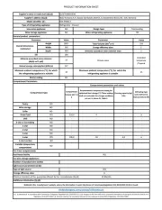
Produkt Specifikationer
Mærke: | Hoshizaki |
Kategori: | Køleskab |
Model: | PT1A-FG-FG |
Har du brug for hjælp?
Hvis du har brug for hjælp til Hoshizaki PT1A-FG-FG stil et spørgsmål nedenfor, og andre brugere vil svare dig
Køleskab Hoshizaki Manualer

11 Januar 2025

26 December 2024

29 August 2024

29 August 2024

29 August 2024

29 August 2024

29 August 2024

29 August 2024

29 August 2024

29 August 2024
Køleskab Manualer
- Køleskab Kenwood
- Køleskab Orima
- Køleskab Dacor
- Køleskab Kolpak
- Køleskab Bifinett
- Køleskab Beverage-Air
- Køleskab Wells
- Køleskab Mestic
- Køleskab Vedette
- Køleskab Nemco
- Køleskab Hotpoint Ariston
- Køleskab Azure
- Køleskab Crosley
- Køleskab Les Petits Champs
- Køleskab MSW
Nyeste Køleskab Manualer

10 Juni 2025

10 Juni 2025

10 Juni 2025

10 Juni 2025

10 Juni 2025

10 Juni 2025

10 Juni 2025

10 Juni 2025

10 Juni 2025

10 Juni 2025