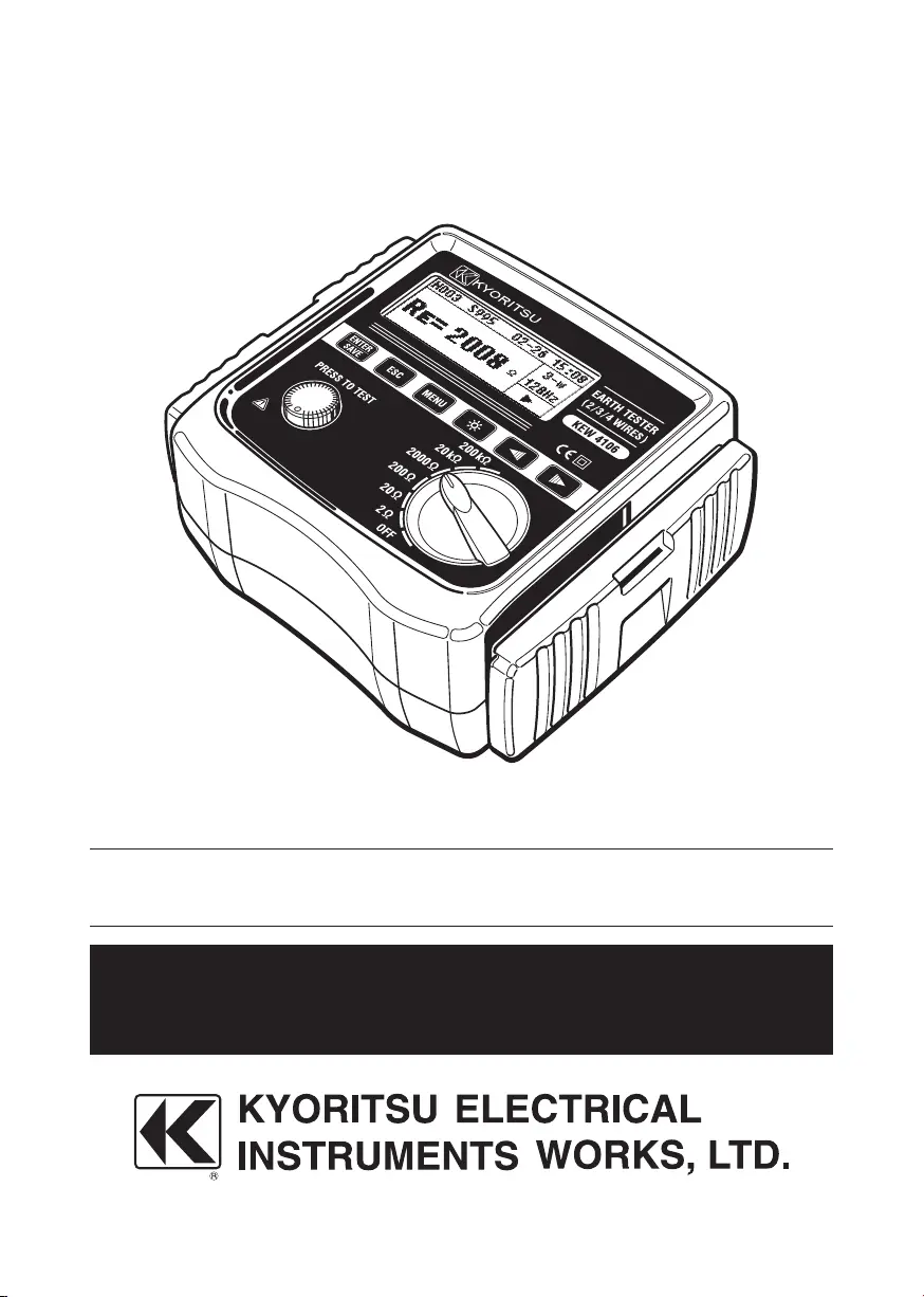
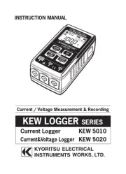
Kyoritsu KEW 4106 Manual


Læs gratis den danske manual til Kyoritsu KEW 4106 (50 sider) i kategorien Måleudstyr. Denne vejledning er vurderet som hjælpsom af 21 personer og har en gennemsnitlig bedømmelse på 4.5 stjerner ud af 11 anmeldelser. Har du et spørgsmål om Kyoritsu KEW 4106, eller vil du spørge andre brugere om produktet?

Side 1/50
InstructionManual
EarthResistance/EarthResistivityTester
KEW 4106
 Contents
1.SafetyWarnings...............................................................................................1
2.HowtostoretheCover....................................................................................5
2-1MethodofremovingtheCover...............................................................5
2-2MethodofstoringtheCover...................................................................5
3. Features.............................................................................................................6
4. Specifications...................................................................................................7
5. InstrumentLayout.......................................................................................... 10
6. MarksandmessagesontheLCD.............................................................. 14
7. MeasurementPrinciple................................................................................. 15
7-1PrincipleofEarthResistanceMeasurements................................... 15
7-2PrincipleofEarthResistivity(ρ)Measurements.............................. 15
8. PreparationforMeasurement....................................................................... 16
8-1BatteryVoltageCheck........................................................................... 16
8-2Settings................................................................................................... 16
 8-2-1SettingItems................................................................................... 16
 8-2-2SettingforMeasurementMethod................................................ 17
 8-2-3SettingforMeasurementFrequency............................................ 17
 8-2-4Site(location)No.Setting............................................................ 18
 8-2-5SettingfortheintervalbetweenAuxiliaryEarthSpikes
   atEarthResistivity(ρ)Measurements....................................... 19
 8-2-6DateandTimeSetting.................................................................... 19
 8-2-7Settingfortheresidualresistance(Rk)ontheTestLeads..... 22
8-3Backlight................................................................................................. 23
8-4Auto-Power-Off....................................................................................... 23
8-5SeriesInterferenceVoltage(EarthVoltage)Measurement............. 24
8-6AuxiliaryEarthResistanceMeasurement.......................................... 24
8-7ConnectionofEarthTestLeadsandSimplified
 MeasurementProbes............................................................................. 24
1
1.SafetyWarnings
This instrument has been designed, manufactured and tested according to
IEC 61010: Safety requirements for Electronic Measuring apparatus, and
deliveredinthebestconditionafterpassingqualitycontroltests.
This instruction manual contains warnings and safety rules which have to
be observedby the user to ensure safe operationof the instrument and
to maintain it in safe condition. Therefore, read through these operating
instructionsbeforeusingtheinstrument.
#WARNING
●Readthroughandunderstandtheinstructionscontainedinthismanual
beforeusingtheinstrument.
Keep themanualathandto enablequick reference whenever
necessary.
●Theinstrumentistobeusedonlyinitsintendedapplications.
Understand and followallthesafetyinstructions contained in the
manual.
Failure to follow the instructions may cause injury, instrument damage
and/or damage to equipment under test. Kyoritsu is by no means liable
for any damage resulting from the instrument in contradiction to this
cautionarynote.
The symbol # indicatedontheinstrument,means thattheuser
must refer to the related parts in the manual for safe operation of the
instrument.
○Readtheinstructionsfollowingcarefullyeach#symbolinthemanual.
#DANGER:is reserved for conditions and actions that are likely to
causeseriousorfatalinjury.
#WARNING:is reserved for conditions and actions that can cause
seriousorfatalinjury.
#CAUTION:is reserved for conditions and actions that can cause
injuryorinstrumentdamage.
2
#DANGER
●Never make measurement on a circuit in which electrical potentials
exceedingAC/DC300Vexist.
●Do not attempt to make measurement in the presence of flammable
gasses. Otherwise, the use of the instrument may cause sparking,
whichcanleadtoanexplosion.
●Never attempttousethe instrument ifitssurface or your handare
wet.
●Becarefulnottoshort-circuitthepowerlinewiththemetalpartofthe
testleadswhenmeasuringavoltage.Itmaycausepersonalinjury.
●Donotexceedthemaximumallowableinputofanymeasuringrange.
●DonotpresstheTestButtonbeforeconnectingtheTestLeads.
●NeveropentheBatterycoverduringameasurement.
●The instrument should be used only in its intended applications or
conditions. Otherwise, safety functions equipped with the instrument
donotwork,andinstrumentdamageorseriouspersonalinjurymaybe
caused.
#WARNING
●Never attempt to make any measurement if any abnormal conditions,
such as a broken cover or exposed metal parts are present on the
InstrumentandTestLeads.
●DonotrotatetheRangeSwitchwiththeTestLeadsconnectedtothe
equipmentundertest.
Do not install substitute parts or make any modification to the
instrument.
Return the instrument to your local KEW distributor for repair or
re-calibrationincaseofsuspectedfaultyoperation.
●Donotreplacebatteriesiftheinstrumentiswet.
●Ensurethatthetestleadsarefirmlyinsertedintotheterminal.
●SettheRangeswitchtoOFFpositionwhenopeningtheBatterycover
forbatteryreplacement.
●Stopusingthetestleadiftheouterjacketisdamagedandtheinner
metalorcolorjacketisexposed.
4
Symbols
Instrumentwithdoubleorreinforcedinsulation
#
Usermustrefertotheexplanationsintheinstructionmanual.
Earth
This instrument satisfies the marking requirement defined in the
WEEE Directive (2002/96/EC). This symbol indicates separate
collectionforelectricalandelectronicequipment.
Measurementcategories(Over-voltagecategories)
Toensuresafeoperationofmeasuringinstruments,IEC61010establishes
safety standards for various electrical environments, categorized as O to
CATIV,andcalledmeasurementcategories.
Higher-numbered categories correspond to electrical environments with
greatermomentaryenergy,soameasuringinstrumentdesignedforCATIII
environments can endure greater momentary energy than one designed for
CATII.
O :Circuitswhicharenotdirectlyconnectedtothemainspower
supply.
CATII :Primary electrical circuits of equipment connected to an AC
electricaloutletbyapowercord.
CATIII :Primaryelectricalcircuitsoftheequipmentconnecteddirectly
to the distribution panel, and feeders from the distribution
paneltooutlets.
CATIV :Thecircuitfromtheservicedroptotheserviceentrance,and
tothepowermeterandprimary overcurrentprotectiondevice
(distributionpanel).
O: Device which is
not directly
connected to the
mains power supply
5
2.HowtostoretheCover
This instrument has a dedicated Cover to protect against impacts from
theoutsideandprevent the instrumentbody from becoming dirty.The
Cover can be detached and put on the backside of the main body during
measurements.
2-1MethodofremovingtheCover
Slideandpullthe Coverin
thedirectionofanarrow.
2-2MethodofstoringtheCover
TurntheCover, slideand
pushitinthedirectionof
arrow.
fig.1
fig.2
6
3.Features
KEW4106 is a2/ 3/4-Wire Digital Earth Resistance/ Earth Resistivity
Tester equipped with a microcomputer and can measure earth resistances
andcalculateearthresistivities (ρ).Thisinstrumentcan measureearth
resistancesonpowerdistributionlines,in-housewiringsystemandelectrical
appliancesetc.duetothelowoutputvoltage:approx10Vrmsorless.
●Designedtomeetfollowingsafetystandards.
 IEC61010-1,IEC61010-2-030(CATIII300V,CATIV150V,Pollution
degree2)
 IEC61010-031(Requirementsforhand-heldProbes)
 IEC61557-1,5(EarthResistanceTester)
●Stablemeasurement results canbeobtained under anoisy environment
byintroducingtheFFT(FastFourierTransform)technology.
●Dot-matrix192x64,MonochromeLCD
●Backlightfunctiontoviewthetestresultsindimlyareas
●Canswitchfrequenciesofmeasuringsignal
 4-kindoffrequencies:94/105/111/128Hz,areselectablebyhand
orautomatically.
●Rk Function is available to cancel the residual resistance on the Test
Leads.
●BatteryCheckFunction
●CanmeasureSeriesInterferenceVoltage/Frequency
 VoltagevaluesandfrequenciesaredisplayedwhenSeries
 Interferencevoltage(AC)exist.
●AuxiliaryEarthResistanceMeasurementFunction
 Auxiliaryearthresistancesaremeasuredanddisplayed.
●WarningforAuxiliaryEarthResistanceMeasurements
 WarningsaredisplayedontheLCDwhenauxiliaryearthresistancesare
toohighandmayresultininaccuratemeasurements.
●Auto-Power-OffFunction
 Theinstrumentisautomaticallypoweredoffwhen5minpasseswithout
anyKeyoperation.
●MemoryFunction
 Cansave800measuredresults.
●CommunicationInterface
 Can transfer the saved data in the instrument to a PC via a supplied
OpticalAdaptor.
7
4.Specification
●ApplicableStandards
 IEC61010-1 MeasurementCATIII300V,CATIV150VPollution
degree2
 IEC61010-2-030 MeasurementCATIII300V,CATIV150VPollution
degree2
 IEC61010-031 Standardforhand-heldProbes
 IEC61557-1,5 EarthResistanceTester
 IEC61326-1 EMCStandard
 IEC60529 IP54
 EN50581 RoHS
●Measuringrangeandaccuracy(23ºC±5ºC,relativehumidity45
˜
75%RH)
Function Range Resolution MeasuringRange Accuracy
Earth
Resistance
Re
(Rgatρ
measurement)
0.001Ω 0.030〜2.099Ω ±2%rdg.±0.03Ω
20Ω 0.01Ω 0.03〜20.99Ω
Note1)
±2%rdg.±5dgt
200Ω 0.1Ω 0.3〜209.9Ω
2000Ω 3〜2099Ω
20kΩ 10Ω 0.03k〜20.99kΩ
200kΩ 100Ω 0.3k〜209.9kΩ
AuxiliaryEarth
Resistance
Rh,Rs
8%ofRe+Rh+Rs
Earth
Resistivity
ρ
0.1Ω
m
~1Ω
m
Auto-
ranging
0.2〜395.6Ω
Note2)
ρ= 2×π×a×Rg
20Ω 0.2〜3956Ω
200Ω 20〜39.56Ω
2000Ω 0.2395.6Ω
20kΩ
2.01999Ω
200kΩ
Series
Note3)
Interference
Voltage
Ust(A.Conly)
50V 0.1V 0
~
50.9Vrms
±2%rdg.±2dgt
(50/60Hz)
±3%rdg.±2dgt.
(40
~
500Hz)
Frequency
Fst
Auto-
ranging
0.1Hz
1Hz
40Hz
~
499.9Hz ±1%rdg.±2dgt
Note1)Auxiliaryearthresistanceis100ΩwithRkcorrection
Note2)DependingonthemeasuredRg.Interval[a]betweenauxiliaryearth
spikesis1.0
~
30.0m
Note3)Thisinstrumentisnotdesignedtomeasurevoltagesoncommercial
powers.
8
●MeasuringmethodforEarthResistance
  
Fall-of-potentialmethod(currentsandvoltagesmeasuredviatheProbes)
●MeasurementmethodofEarthResistivity(ρ)
  Wenner4-polemethod
●OutputCharacteristics
  MeasuringVoltageUm (max.) approx 10Vrms 94Hz, 105Hz, 111Hz,
128Hz
  MeasuringCurrentIm (max.)approx80mA,however,Im×(Re+Rh)
<Um
●MeasuringMethodforSeriesInterferenceVoltage(earthvoltage)
  RMSRectifier(betweentheE-STerminals)
●MemoryCapacity:800data
●CommunicationInterface :Model8212USBOpticalAdaptor
●LCD Dot-matrix192×64,monochrome
Backlight
Earthresistance :max209.9kΩ
Earthresistivity :1999kΩ・m
SeriesInterferenceVoltage :max50.9V
●LowBatteryWarning :Batterymarkappears.
●ContinuousMeasurement :400timesormorewithmanganesebatteries;
repeatingmeasurementsatevery30sec
withaloadof1Ωat2ΩRange.
●Over-rangeIndication :OL
Auto-Power-Off :automaticallypoweredoffwhen5min
passeswithoutanyKeyoperation.
●Locationforuse :
Indoor/Outdooruse(Notcompletelywaterproof),
altitude2000morless
●Applicablerange :
Testingearthresistanceonpowerdistribution
lines, in-house wiringsystem and electrical
appliances
●Temperature&Humidityrange(guaranteedaccuracy):
  23℃±5℃ ,relativehumidity85%orless(nocondensation)
●OperatingTemperature&Humidityrange:
  -10℃
~
50℃ ,relativehumidity75%orless(nocondensation)
●StorageTemperature&Humidityrange:
  -20℃
˜
60℃ ,relativehumidity75%orless(nocondensation)
●OverloadProtection:betweenE-S(P)andbetweenE-H(C)terminals
  AC280V/10sec
●WithstandVoltage :betweentheelectricalcircuitandenclosure
AC3540V(50/60Hz)/5sec
●InsulationResistance :betweentheelectricalcircuitandenclosure
50MΩormore/DC1000V
9
●Dimension 167(L)x185(W)x89(D)mm
●Weight approx900g(includingbatteries)
●PowersourceDC12V:sizeAAmanganesedrybattery(R6P)x8pcs
*Inauseofthisinstrumentunderlowtemperaturebelow0ºC,auseof
alkalinebatterieswithlowtemperaturespecisrecommended.
●Operatinginstrumentaluncertainty
 
Operatinginstrumentaluncertainty(B)isanerrorobtainedwithintherated
operating conditions, and calculated with the intrinsic error (A), which is
anerroroftheinstrumentused,andtheerror(En)duetovariations.
          
)15.1(
2
5
2
4
2
3
2
2
EEEEAB ++++±=
A:Intrinsicerror
E
2
:Variationduetochangingthesupplyvoltage
E
3
:Variationduetochangingthetemperature
E
4
:Variationduetoseriesinterferencevoltage
E
5
:Variation due to resistance of the probes and auxiliary earth electrode
resistance
●Rangetokeepthemaximumoperatingerror
 Measurement range within which the maximum operating error (±30%)
applies.
2ΩRange :0.5Ω
˜
2.099Ω
20ΩRange :2Ω
˜
20.99Ω
200ΩRange :20Ω
˜
209.9Ω
2000ΩRange:200Ω
˜
2099Ω
20kΩRange :2kΩ
˜
20.99kΩ
200kΩRange :20kΩ
˜
209.9kΩ
  VariationofSupplyVoltage:untiltheBatteryWarningmarkappears
  TemperatureVariation:-10℃
~
50℃
SeriesInterference Voltage: 162/3Hz, 50Hz, 60Hz,400Hzand
DC3V
  *Noneed toconsider DC Seriesinterference voltagesat 2Ω &20Ω
Ranges
  Auxiliary earth electrode resistance : within following range or 50kΩ
orlesswhicheversmaller(Atρmeasurements,"Re"inthisformulais
replacedwith"Rg".)
Rh,Rslimit Accuracy
Re<0.40Ω 1kΩ
±5%rdg±1%fs
0.4Ω≦Re<1.00Ω 2kΩ
1.00Ω≦Re<2.00Ω 3.5kΩ
2.00Ω≦Re =Rex100+5kΩ(Rh,Rs<50kΩ)
10
5.InstrumentLayout
●InstrumentbodyandConnector
① LCD
② ENTER/SAVEKey
③ ESCKey
④ MENUKey
⑤ BacklightKey
⑥ CursorKey
⑦ TESTButton
⑧ RangeSwitch
⑨ EarthTerminalE
⑩ ProbeTerminalESfortheEarthTerminalside
⑪ ProbeTerminalS
⑫ AuxiliaryEarthTerminalforCurrentH
⑬ TerminalsforOpticalAdaptor
11
●LCDIndications
●Accessories
#DANGER
●
DonotconnectthePrecisionMeasurementTestLeadswhereelectrical
potentialsexceeding33Vrmswithpeakvalueof46VorDC70V.
 
PleaseusetheSimplifiedMeasurementTestLeadsforvoltagemeasurement.
The Alligator clips need to be attached and used under CAT III / IV test
environmentsandtheFlatTestBarsareunderCATIItestenvironment.
 PrecisionMeasurementTestLeadsMODEL7229A
 (red40m,yellow20m,black20m,green20m)
SimplifiedMeasurementTestLeadsMODEL7238A
MemoryNo.
SiteNo.
Month-Day
Time
Wiring
Measuringsignal
frequency
CursorKeyisactive.
MainDisplay
ResultDisplayScreen
12
[Howtoattach]
Firmlyinsertandconnecttheadapteryouwanttousetotheendof
thecord(withbananaplugsatbothends).
Inserttheplugoftestleadsfirmlyintoeachterminal.Iftheyarenot
insertedfirmly,thelooseconnectionmaycauseinaccuratereadings.
ProtectiveFingerguard:It is a part providing protection against electrical
shock and ensuring the minimum required air and
creepagedistances.
#DANGER
To avoidgetting electricalshocks,ensure thattestleads are
disconnectedfromtheinstrumentwhenreplacingthemetaltipor
adapterfortestleads.
Alligator clip
Protective
Fingerguard
Banana plugs, both ends
Flat test bar
Protective
Fingerguard
13
AuxiliaryEarthSpikeMODEL8032x2sets(4spikesintotal)
CordReelMODEL8200-04x1set(4reelsintotal)(forMODEL7229A)
OpticalAdaptorMODEL8212USBx1set
CommunicationSoftwareCD-ROMKEWReportx1pce
SizeAAManganesebattery(R6P)x8pcs
CarryingcaseMODEL9125
Shoulderstrapx1pce
14
6.MarksandMessagesdisplayedontheLCD
Followingmarksandmessagesaredisplayedwhilemeasurements.
MarksandMessages Details
Batteryvoltageislow.Replacethebatteries.
Thismarkisbeingdisplayedduringameasurement.
MeasuringrangefortheselectedRangeis
exceeded. In case of Ust measurements, 50V or
moreisdetected.
Failedtomakesuccessfulmeasurements
Rkisexceededthelimitvalue;exceeding2Ωat2
ΩRangeandexceeding9Ωat20ΩRange.
SettingforRkcanbemadeat20Ωorlower
Setting for Rk can be made only at 2w, 3w, 4w
measurements.
UstisRegulatedvalueormore.
Rh and Rsvaluesexceed the allowable range.
Correctresultsmightnotbeobtained.
Nosaveddataexists.
Memoryisfull.Nomoredatacansavedin.
Aconfirmationmessagebefore deleting the
selecteditem.
A confirmation message beforedeletingthe all
items.
Allitemshavebeendeleted.
NxxxisaMemoryNo.,andtheleftmessage
saying 95 data have been stored. (Displayed at
theDataReviewScreen.)
Indicatingthemeasuredresultissavedwith
MemoryNo.N003.
The characterS standsforSite. Selectable
from000to999.
Dataissuccessfullysaved.
15
7.MeasurementPrinciple
7-1PrincipleofEarthResistanceMeasurements
Thisinstrumentmakesearthresistancemeasurementswithfall-of-potential
method,whichisamethodtoobtainearthresistancevalueRxbyapplying
ACcurrentI between the measurement objectE (earthelectrode) and
H(C)(currentelectrode),andfindingoutthepotentialdifferenceVbetween
E (earth electrode) andS(P) (potential electrode). This unit outputs test
voltageUmto generateAC currentI. Earth resistancevalueRxis
determinedbytheACcurrentIandpotentialdifferenceV.SeeFig. 3.
7-2PrincipleofEarthResistivity(ρ)Measurements
AccordingtotheWenner4-polemethod,applyACcurrentIbetweenthe
E(earthelectrode)andH(C)(currentelectrode)tofindoutthepotential
differenceV between the potential electrodeS(P)and auxiliary earth
electrodesES.(Fig.4)
ToobtaintheearthresistanceRg(Ω),devidethepotentialdifferenceV
byACcurrentI;wheretheintervalbetweenelectrodedsisa(m).Then
useaformula:ρ= 2・π・a・Rg(Ω・m)
Fig.3
Fig.
4
16
8.PreparationforMeasurement
8-1BatteryVoltageCheck
Powerontheinstrument.IfthedisplayisclearwithouttheLowbatterymark
"
"showing,batteryvoltageissufficient.Ifthedisplayblanksorthe
Lowbatterymarkisindicated(Fig.5),replacethebatteriesaccordingto11.
forBatteryandFuseReplacement.
Note)Measurements cannot be made, even the Test Button is pressed,
whiletheLowBatteryMarkisdisplayedontheLCD.Measurements
arehaultwhentheLowBatteryMarkappearsontheLCD.
8-2Settings
8-2-1SettingItems
This instrument starts with Measurement mode (Fig.6 Main Screen) when
itispoweredonwhiletheRangeSwitchhasbeensettothepositionother
thanOFF.
Measurementconditionsshouldbesetbeforestartingmeasurements.
Settingthedateandtimeenablesasavingmeasureddata with time
information.Pressthe
KeyandenterintotheSYSTEMMENU
(Fig.7).ThenselectCONFIGSETTINGwithCursorKeys,andpressthe

KeytoenterintotheCONFIGSETTINGmode.(Fig.8) Pressing
the KeytwiceexitsfromtheCONFIGSETTINGmodeandreturns
toMeasurementmode.
Fig.6MainScreen
Fig.7 Fig.8
Fig.5Lowbatterymark
17
Settingsoffollowingparameterscanbemadeonthisinstrument
●Wire :Measurementmethod(WiringSystem)
●Freq :Measurementfrequency
●Site :Site(location)No
●Lh :IntervaloftheauxiliaryearthspikesatEarthresistivity(ρ)
measurement
●Date/Time :Year/Month/Day,Time(24-hourdisplay)
●Rk :ResidualresistanceontheTestLeads
8-2-2SettingforMeasurementMethod
Measurement methodisselectable from:2-wire(2-wire system),3-wire
(3-wiresystem),4-wire(4-wiresystem)andρ(earthresistivity).
SelectWirewiththeCursorKeyontheCONFIGSETTINGScreenand
pressthe
KeytoproceedtotheWiringSettingScreen.(Fig.9)
SelecttheappropriateWiringSystemwiththeCursorKeyandpressthe
 Key.ThentheCONFIGSETTINGScreenwiththeselectedWiring
Systemwillbedisplayed.
8-2-3SettingforMeasurementFrequency
Measurementsignalfrequenciescanbeselectedfromfollowingfour
frequency bands with this instrument in order to minimize the influence of
theseriesinterferencevoltage(earthvoltage).
*Auto*94Hz*105Hz*111Hz*128Hz
Theinstrumentautomaticallyselectthebestsuitablefrequencywhen
selectingAuto and output the frequency signal. SelectFreq with the
CursorKeyontheCONFIGSETTINGScreenandpressthe Keyto
displaytheFrequencySettingScreen(Fig.11).
Fig.
9
Fig.
10
Fig.
11
18
SelectingadesirablefrequencywiththeCursorKey,andpressingthe

KeyreturnstotheCONFIGSETTINGScreen(Fig.12)withthe
selectedfrequency.
8-2-4Site(location)No.Setting
Thesite(location)wheremeasurementsdonecanbesavedwithnumbers.
SelectSite with the CursorKey on the CONFIGSETTING Screen, and
pressthe KeytodisplaytheSiteNumberSettingScreen(Fig.13).
SelectanydigittobechangedwiththeCursorKey,andpressthe 
Key.Thentheselecteddigitishighlightedandreadytobechanged.(Fig.14)
Press theRight CursorKey toincrease numbersand theLeft Cursor
Key toreducenumbers.KeeptheCursorKeypresseddowntochange
numbersquickly.Pressthe Keytoconfirmanumber.
Repeat this procedure to change the other digits. Press the Key
whensettingsaredone.ThentheCONFIGSETTING Screen (Fig.15)with
theselectedSiteNo.willbedisplayed.
Note)SiteNo.isselectablefrom000to999.
Fig.12
Fig.13
Fig.14
Fig.15
19
8-2-5SettingfortheintervalbetweenAuxiliaryEarthSpikesatEarth
Resistivity(ρ)Measurements
Makingsettingoftheintervalsbetweenauxiliaryearthspikesisnecessary
tomeasureearthresistivity(ρ).
SelectLhwiththeCursorKeyontheCONFIGSETTINGScreen,and
pressthe
KeytodisplaytheLengthSettingScreen(Fig.16).
SelectanydigittobechangedwiththeCursorKey,andpressthe 
Key.Thentheselecteddigitishighlightedandreadytobechanged.(Fig.17)
Press the Right Cursor Key to increase numbers and the Left Cursor
Key toreducenumbers.KeeptheCursorKeypresseddowntochange
numbersquickly.Pressthe Keytoconfirmanumber.
Repeat this procedure to change the other digits. Press the Key
whensettingsaredone.ThentheCONFIGSETTINGScreen(Fig.18)witha
newintervalwillbedisplayed.
Note)Intervalscanbesetwithinarangeof1.0to30.0m.Ifalongerinterval
out of this range is entered at the Setting Screen, it automatically
changedto30.0mwhenpressingthe Key.
Note)Intervals up to 20m can be selected with the supplied Test Leads
MODEL7229A.
8-2-6DateandTimeSetting
Thisinstrumenthasaclockfunctionandcansavethemeasureddatawith
timeanddateinformation.Theclockwillnotberesetonceithasbeenset
evenafterpowering off theinstrument.Amanualadjustment isrequiredto
keeptheclocktimealwaysright.
Fig.
16
Fig.
17
Fig.
18
20
TimeSettingcanbedoneinfollowingprocedure.
SelectDate/TimewiththeCursorKeyontheCONFIGSETTINGScreen,
and press the
Key to display the Time and Date Setting Screen
(Fig.19).
(1)TimeSetting
PutthecursoronTimeandpressthe KeytodisplaytheTime
SettingScreen(Fig.20).
SelectaparametertobechangedwiththeCursorKey,andpressthe 
Key.Thentheselecteddigitishighlightedandreadytobechanged.(Fig.21)
Theclockis24-hourdisplay.
Press theRightCursorKey to increase numbers and the Left Cursor
Key toreducenumbers.KeeptheCursorKeypresseddowntochange
numbersquickly.Pressthe
Keytoconfirmanumber.
Repeatthisproceduretochangetheotherdigits.Pressingthe Key
whensettingsaredonereturnstotheTime/DateSettingScreen(Fig.22).
Tochangethedate,proceedtoStep(2).Pressthe Keyagaintoexit
from the setting mode and return to the CONFIGSETTING Screen. Then
theclockstarts.
Fig.
19
Fig.
20
Fig.
21
Fig.
22
21
(2)DateSetting
Dateisdisplayedinthefollowingorder:Month/Day/Year.
PutthecursoronDateandpressthe
KeytodisplaytheDate
SettingScreen(Fig.23).
SelectaparametertobechangedwiththeCursorKey,andpress
the  Key. Then the selected digit is highlighted and ready to be
changed.(Fig.24)
Press the RightCursor Key
to increasenumbers and the Left Cursor
Key toreducenumbers.KeeptheCursorKeypresseddowntochange
numbersquickly.Pressthe
Keytoconfirmanumber.
Repeatthisproceduretochangetheotherdigits.Pressingthe
Key
whensettingsaredonereturnstotheTime/DateSettingScreen(Fig.25).
Pressthe Keyagaintoexitfromthesettingmodeandreturntothe
CONFIGSETTINGScreen.Thentheclockstarts.
Note)The second is not displayed on the Main Screen; only hours and
minutesaredisplayed.
Note)Thebackupbatterymaybeexhaustedwhenclockbecomeswrong
after powering on/off the instrument. In this case, please contact
ourlocaldistributor.Thelifetimeofthebackupbatteryisapprox5
years.
Fig.
23
Fig.
24
Fig.
25
22
8-2-7Settingfortheresidualresistance(Rk)ontheTestLeads
This instrument can store the residual resistance (Rk) of the Test Leads
beforestartingRemeasurements on2/ 3/4-wire system,and candeduct
theresistancefrom themeasuredresult.The settingofRkcanbedonein
followingprocedure.
Note)ConnectionsofTestleadsvarybymeasurementmethods.
 Seethecorrespondingpagesforfurtherdetails.
Note)Rk cannot besavedwhiletheLowBattery Mark
or
isdisplayedontheLCD.
Selectthe2Ωor20ΩRange.
SelectRk with the Cursor Key on the CONFIGSETTING Screen, and
pressthe
KeytodisplaytheRkSettingScreen(Fig.26)
PresstheTestButtontomeasureRk.Themeasuredresultswillnotbesaved
untilthe
Buttonispressed.TheCONFIGSETTINGScreen(Fig.27)
isdisplayedwhentheButtonispresseddownandthedataissaved.
TheRk valueisbeingkepteven poweringoff theinstrument.Toclearthe
savedRkvalues,selectClearontheRkSettingScreen(Fig.28)andpress
the
Key.Thenthevaluerestoresto0.000Ω.
ThenCONFIGSETTINGScreen(Fig.29)isdisplayedagain.
Note)Rkvaluesexceedingfollowingvaluescannotbesaved.
2ΩRange:max2Ω,20ΩRange:max9Ω
AmessageshowninFig.30isdisplayedwhenthemeasured
Rkisexceedingabovevalues.
Note)ThemessageshowninFig.30isalsodisplayedwhenafuseblows.
Fig.
26
Fig.
27
Fig.
28
Fig.
29
23
Followingmessageappearsandshowsthatthedatacannotbesavedwhen
the
Keyispressedwithabovedisplay.
Note)Following message appears and shows that the data cannot be
saved when trying to save Rk at 200kΩ or upper Ranges. The Rk
valuessavedat2Ωand20ΩRangesarekepteffectiveat200kΩor
upperRanges.
Note)Following message appears and shows that the data cannot be
savedwhentryingtosaveRkatWire(ρ)measurements.
8-3Backlight
To facilitate workingin dimlylit situationsor innight time,a backlight
functionisprovidedwhichilluminatesthe LCD. Press the
Key to
operatethisfunction.Thebacklightwilllightupforabout30secandturned
off automatically. Pressing the Key while the backlight is oncan
turnitoffbymanual.
8-4Auto-Power-Off
This instrument is automatically powered off about in 5 min after the last
switch operation.Toexitfromtheauto-power-off mode, settheRange
SwitchtoOFFpositiononce,and re-set ittotheRangeatwhicha
measurementtobeconducted.
Fig.
30
Fig.
31
Fig.
32
Fig.
33
24
8-5SeriesInterferenceVoltage(EarthVoltage)Measurement
Measurementsareautomaticallystarted during a measurement of earth
resistances and earth resistivities, and the results can be checked on the
Resultdisplayscreen.
Warning messageVoltage High! is displayed on the Main display when
theearthvoltage(Ust)ishigh.
2Ω/20ΩRange :VoltageHigh!warningappearswhenthe
voltageis12Vorhigher.Earthresistance
measurement cannot be made when the voltage
exceeds15V.
200Ω〜 200kΩRange
:VoltageHigh!warningappearswhenthe
voltageis15Vorhigher.Earthresistance
measurement cannot be made when the voltage
exceeds20V.
Note)DCseriesinterferencevoltagescannotbemeasured.
8-6AuxiliaryEarthResistanceMeasurement
This instrument can measure and displaythe auxiliary earth resistances
(Rh, Rs).When the Rh or Rs value is more than Regulated value or50k
Ω,awarningmessage
or appear.TheLCD
showsRh=OL Ω orRs=OL when the Rh or Rs values exceed 50kΩ
.Theseparametersaremeasuredautomaticallyatauxiliaryearthresistance
measurements,andcanbecheckedontheResultDisplayScreen.
Note)Rhand Rs stand for Auxiliary Earth PoleH(C) and the Auxiliary
EarthResistanceofS(P)respectively.
8-7ConnectionofEarthTestLeadsandSimplifiedMeasurementProbes
Connect the Earth Test Leads and Simplified Measurement Probes to the
connectorsontheinstrumentfirmly.Otherwise,acontactfailureoccursand
wrongresultsmaybereadoutontheLCD.
Note)SomenumbersotherthanOLmaybedisplayedontheLCDwhen
makingmeasurementwithoutconnectinganycordorprobeat200Ω
orupperRanges.Thisisnotamalfunction.
25
9.MeasurementMethod
#DANGER
●Novoltageshouldbeappliedbetweenthemeasuringterminalsatearth
resistancemeasurements.
9-1EarthResistanceMeasurement
#CAUTION
●Themeasuredresultsmaybeinfluencedbyinductionifmeasure-ments
are made with the Test Leads twisted or in touch with each other.
WhenconnectingtheProbes,theyshouldbeseparated.
Note)Whenmeasuringmulti-earthedsystemsuchasinterconnectedtowers
andelectricalpoleswith thisinstrument, themeasured results
smaller than the valuesofsingle-earthedsystemareobtainedsince
these earth resistance can be considered that they are connected
inparallel. Letsregard earthresistanceundertestasRx,andthe
otherearthresistancesasR1,R2,•••Rn.
Oftheseearthresistances,R1,R2,•••Rncanbeconsideredthattheyare
connectedinparallel. And can beregardedas a combinedresistanceRs.
The Rs can be regarded small enough against Rx since it is a combined
resistanceconsists ofseveralresistances.Sothemeasuredvalues
obtained by using this instrument will be quite small since Rs values are
measuredactually.Tomeasureearthresistancesofmulti-earthedsystem,a
useofourDigitalEarthClampMODEL4200isrecommended.
=
=
26
9-1-1PreciseMeasurement(3-Wire)*withEarthTestLeadsMODEL7229A
Thisisastandardmethodtomeasureearthresistances.Themeasuredearth
resistancesarefreeofauxiliaryearthresistancesbuttheresistancesonthe
Eterminalarecontained.
Terminalstobeused :E,S(P),H(C)Terminals
TestLeads :connecttotheE,S(P),H(C)Terminals
AuxiliaryEarthSpike :2pcs,connecttotheS(P)andH(C)terminal
(1)SettingofWiringSystem
SelectWire (3) with reference to8-2-2 Setting for Measurement
Methodinthismanual.
(2)SettingofRk
1.Firmly inserteach plugof 3test leads(green, yellow, red) to the
correspondingconnectorsontheinstrument.
2.Selectthe2Ωor20ΩRange.
3.Engage3Alligatorclipstoshort-circuitallofthem.
4.SavetheRkvalues withreference to8-2-7Settingfor theresidual
resistanceontheTestLeads.
Note)A break in Test Leads or burnout of Fuse is suspected when the
LCDshowsRk=OLΩwhile3TestLeadsarebeingshorted.
(3)ConnectionofAuxiliaryEarthSpikesandTestLeads
SticktheAuxiliaryEarthSpikesS(P) andH(C) into the ground
deeply.Theyshouldbealignedatanintervalof5-10mfromtheearthed
equipmentundertest.Connect thegreenTestLeadto theearthed
equipmentundertest,theyellowTestLeadtotheAuxiliaryEarthSpike
S(P) andtheredTestLeadtotheAuxiliaryEarthSpikeH(C).
(Fig.34)
YellowYellow
Red
Green
Earthed Electrode
under Test
Auxiliary
earth spikes
Fig.
34
27
(4)EarthResistanceMeasurement
Select a Range (any Range is ok) when the connection is done, and
presstheTESTButton.Amessage
isdisplayed
attheupperrightontheLCD.ThemeasuredearthresistancesReare
displayedontheLCDwhenameasurementisfinished.(Fig.35)
PressingtheCursorKey
displaystheResultDisplayScreen
(Fig.36)tovieweachparameter.
Pressthe KeytoreturntotheMainScreen.
Note)
Thereadingsmaynotcorrect when the auxiliaryearthresistanceis
toohigh.SticktheAuxiliaryEarthSpikesS(P)andH(C)inthemoist
part of thesoil.Ifa message
or 
appear on the LCD, auxiliary earth resistance is too high to make
measure-ments.RechecktheconnectionofTestLeads.
Giveenoughwaterwherethespikeshavetobestuckintothedry,
stony or sandy part of the earth so that it may become moist. In
caseofconcrete,laytheAuxiliaryEarthSpikedownandwaterit,or
putawetclothetc.onthespikewhenmakingmeasurements.
Fig.
35
Fig.
36
28
#DANGER
TheRemeasurementcannotbemadewhenawarningmessageVoltage
High!!likeshowninFig.37appearontheLCD.Voltagesmorethan15V
existbetweentheEandS(P)terminals.
Pressingthe
KeyshiftsthedisplayasshowninFig.38.
ThemessageUst=OLVmeanstheUstismorethan50V.
To avoid this, make measurements after reducing the earth voltages by
turningoffthepowersupplyoftheequipmentundertestetc.
9-1-2PreciseMeasurement(4-Wire)*withEarthTestLeadsMODEL7229A
TheESTerminalisalsousedwiththeotherterminalsusedatthe3-wire
Precise measurements.In this case, more precise results can be obtained
becauseauxiliary earth resistancesofthemeasuredearthresistances
are excluded, moreover, resistance of the Test Leads connected to the E
Terminalcanbecanceled.
Terminalstobeused :E,ES,S(P),H(C)Terminals
TestLeads :connecttotheE,ES,S(P),H(C)Terminals
(theES Test Lead should be connected to the
earthedequipmentunder test wheretheETest
Leadisconnected.)
AuxiliaryEarthSpike :2pcs
(1)SettingofWiringSystem
SelectWire(4) withreference to8-2-2 Settingfor Measurement
Methodinthismanual.
Fig.
37
Fig.
38
29
(2)SettingofRk
The measured results obtained at 4-Wire system are not be influenced
bytheTestLeadsConnectedtotheETerminal,butsettingofRkcan
bemadeonthisinstrument.
1.Firmlyinserteachplugof4TestLeads(green,black,yellow,red),to
thecorrespondingconnectorsontheinstrument.
2.Selectthe2Ωor20ΩRange.
3.Engage4Alligatorclipstoshort-circuitallofthem.
4.Save theRkvalueswithreferenceto8-2-7 Settingfortheresidual
resistance(Rk)ontheTestLeads.
Note)A break in Test Leads or burnout of Fuse is suspected when the
LCDshowsRk=OLΩwhile4TestLeadsarebeingshorted.
(3)ConnectionofAuxiliaryEarthSpikesandTestLeads
SticktheAuxiliaryEarthSpikesS(P)andH(C)intothegrounddeeply.
Theyshouldbealignedatanintervalof 5-10m fromtheearthed
equipment undertest.Connect thegreen TestLeadto theearthed
equipmentundertest,theyellowTestLeadtotheAuxiliaryEarthSpike
S(P)andtheredTestLeadtotheAuxiliaryEarthSpikeH(C).
TheblackTestLeadconnectedtotheESTerminalshouldbe
connectedtotheearthedequipmentundertest.(Fig.39)
(4)EarthResistanceMeasurement
Select a Range (any Range is ok) when the connection is done, and
presstheTESTButton.ThemeasuredearthresistancesReare
displayed on the LCD. The operation procedure is same to that for
3-Wiremeasurements.
Fig.
39
YellowYellow
Red
Green
Earthed Electrode
under Test
Auxiliary
earth spikes
30
Note)Ifamessage or appearontheLCD,
auxiliaryearthresistanceistoohightomakemeasurements.
RechecktheconnectionofTestLeads.
9-1-3SimplifiedMeasurement(2-Wire)*withSimplifiedTestProbesMODEL7238A
#DANGER
●Use a Voltage detector to check the earth of the commercial power
supply.
●Donotusetheinstrumenttochecktheearthofthecommercialpower
supply. A danger will be caused because the voltage may not be
displayedwhenincaseofaliveconductorwhentheconnectionofthe
earthelectrodetobemeasuredhascomeoff,orwhentheconnection
ofthetestleadsoftheinstrumentisnotcorrectetc.
Do not use this instrument tomeasurethevoltageofcommercial
Powersupply.Thisinstrumentisnotdesignedtomeasurevoltagesof
commercialpowersupply.
Whenusingthe supplied SimplifiedTest Probes, theS(P)and
H(C)Terminalswill be short-circuited andthe input impedancewill
be reduced.Theresidualcurrent circuit breaker may operate when
makingmeasurementsofthevoltageinthecircuitwiththebreaker.
●
ELCBsmaytripwhenperformingsimplifiedmeasurementsontheoutlet
ofthecircuitwithELCBssincethisinstrumenthaslargetestcurrents.
Use this method when the Auxiliary Earth Spike cannot be stuck. In this
method, an existing Earth Electrode with a low earth resistance, such as
ametalwaterpipe,acommonearthofacommercialpowersupplyandan
earthterminalofabuilding,canbeusedwiththe2-Wiremethod.
However, the measuredearthresistances containtheauxiliaryearth
resistanceandtheresistanceoftheETestLead.
ThisinstrumentissuppliedwithasetofSimplifiedMeasurementTestLeads
forwhichbothofAlligatorClipsandFlatTestBarcanbereplacedandused
ifnecessary.
Terminalstobeused :E,S(P),H(C)Terminals
TestLeads :one to theE Terminal, Simplified Measurement
Probesto theS andH Terminals and short-
circuittheseTerminals.
AuxiliaryEarthSpike :Noneisused
31
(1)SettingofWiringSystem
SelectWire (2) with reference to8-2-2 Setting for Measurement
Methodinthismanual.
(2)SettingofRk
1.PuttheAlligatorClipstothe2TestLeads(green,red),andconnect
thegreenPlug totheE Terminal and thetwo red Plugsto the
S(P)andH(C)Terminalsrespectively.
2.Selectthe2Ωor20ΩRange.
3.Engage2Alligatorclipstoshort-circuitbothofthem.
4.Save theRkvalueswith reference to8-2-7 Settingfortheresidual
resistance(Rk)ontheTestLeads.
Note)A break in Test Leads or burnout of Fuse is suspected when the
LCDshowsRk=OLΩwhile4TestLeadsarebeingshorted.
(3)Connection
ConnecttheTestLeadsasshowninFig.40.
Note)WhenthesuppliedSimplifiedMeasurementProbesarenotused,the
S(P)andH(C)Terminalsshouldbeshorted.
(4)EarthResistanceMeasurement
SelectahighresistanceRangewhentheconnectionisdone,andpress
theTESTButton. Then the earthresistancevaluesRe aredisplayed
ontheLCD.SelectalowerRangeforthelowearthresistances.
Earthed
Electrode
under Test
Secondary
Primary
Side
Side
Be sure to check
earthed side of
a commercial
power supply.
Supply Transformer
Where earth for mains supply is used.
Fig.
40
32
(5)Measuredresistancesatsimplifiedmeasurements
Two-Wiremethodisusedforthesimplifiedmeasurements.Inthis
method,earthresistanceofthe earthedelectrode(re) connectedtothe
S(P)TerminalisaddedtothetrueearthresistanceRxandshownas
anindicatedvalueRe.
Re(indicatedvalue)=Rx+re
IftheRe is knownbeforehand,trueearthresistancevalue Rx is
calculatedasfollows.
Rx=Re-re
Note)TherecannotbecanceledbythesettingofRk.
9-2EarthResistivity(ρ)Measurement
#CAUTION
●Themeasuredresultsmaybeinfluencedbyinductionifmeasure-ments
are made with the Test Leads twisted or in touch with each other.
WhenconnectingtheProbes,theyshouldbeseparated.
Making a setting of the interval between Auxiliary Earth Spikes first and
measuringtheearthresistanceswiththe4AuxiliaryEarthSpikesstuckinto
thegroundatevenintervals.Thentheinstrumentcancalculateanddisplay
earthresistivityontheLCDautomatically.
Terminalstobeused :E,ES,S(P),H(C)Terminals
TestLeads :connecttotheE,ES,S(P)andH(C)Terminals
AuxiliaryEarthSpike :4pcs
(1)SettingofWiringSystem
SelectWire )with reference to8-2-2 Setting for Measurement
Methodinthismanual.
Note)The instrument doesn't accept any setting change onRk while
measuringearthresistivity(ρ).
(2)ConnectionofAuxiliaryEarthSpikesandTestLeads
StickthefourAuxiliaryEarthSpikesintothegrounddeeply.Theyshould
bealigned atanintervalof1-30m.Thedepth shouldbe5%orlessof
theintervalbetweenthespikes.
33
(e.g.Thespikeshouldbestuckinthedepthof25cmorlesswhenthe
intervaloftheAuxiliaryEarthSpikesis5m.)
IftheSpikesstucktoodeep,itmayresultininaccurateearthresistivity
measurement.
Note)ThesuppliedTestLeadsMODEL7229AcanbeusedfortheSpikes
stuckattheintervalofmax20m.
Note)The lengthof thesupplied AuxiliaryEarth SpikeMODEL 8032 is
20cm.
Connect thegreen, black, yellowTest Leads connected totheE,ES,
S(P)andH(C)TerminalsontheinstrumenttotheAuxiliaryEarthSpikes
fromtheclosesttothefarthestinthisorder.(Fig.41)
(3)SettingoftheIntervalbetweenAuxiliaryEarthSpikes
The interval of the Spikes should be entered according to the setting
made at the step of8-2-5 Setting for the interval between Auxiliary
EarthSpikesatEarthResistivity(ρ)Measurements.
(4)EarthResistivity(ρ)Measurement
Select a Range (any Range is ok) when the connection is done, and
press the TEST Button.Then the measuredearth resistivity (ρ) and
the earth resistanceRg between the ES-S Terminals are displayed.
(Fig.42)
Fig.
42
Fig.
41
34
PressingtheCursorKey
displays parameters like shown in
Fig.43.
Pressthe KeytoreturntotheMainScreen.
IftheRgvalueistoolarge,thedisplayreadsasshowninFig.44.
Inthiscase,rotatetheRangeSwitchandselectanupperRange.
Pressing the Keywhile the measuredresult of ρis being
displayed switches the display as indicated in Fig.16. Then setting of
intervalbetweenauxiliaryearthspikes(Lh)canbemade.Clause8-2-5
describesthedetailedsettingprocedure.
Note)Thedepthshouldbe5%orlessoftheintervalbetweenthespikes.
Ifthe Spikesstuck toodeep, itmay resultin inaccurate earth
resistivitymeasurement.
Note)Accurate earth resistivity measurement will be affected and errors
in measured result becomes large if theRg value is smaller than
the full-scale value at the selectedRange.When theRg andρ
values vary widely at each Range, measurements should be made
againatproperRgRange.
Note)If a message
 o r appear onthe
LCD, auxiliary earthresistance is too high to make measurements.
RechecktheconnectionofTestLeads.
Fig.
43
Fig.
44
Fig.
16
35
10.Store/RecalltheMeasurementResults
Measurementconditionsandmeasuredresultscanbesavedinthememory
oftheinstrument.(max800)
ThestoreddatacanbetransferredtoaPCviaanOpticalAdaptor
Model8212USBbyusingaspecialsoftwareKEWReport.
10-1Howtosavethedata
Pressthe
Keywhenanearthresistancemeasurementisfinished.
ThentheLCDreadsasshowninFig.45.
Pressthe
Keyagain,andthensavedisdisplayedwithhighlighted
atthelowerrightoftheLCDandthemeasuredvaluesaresaved.(Fig.46)
Pressthe KeytoreturntotheMainScreen.
Note)PressingtheTESTButtonagaininitiatesanothermeasurement.
Note)Data cannot be saved while the Low Battery Mark is displayed on
theLCD.
Note)Whenthesaveddatareachestothemaxlimitofthecapacity(800),
FullisdisplayedattheupperleftontheLCDasshown in Fig.47
andnomoredatacanbesaved.
Whentryingtosavedatawithmemorycapacityisfull,amessageshownin
Fig.48isdisplayed.Pressthe KeyandreturntotheMainScreen.
To save new data, it is necessary to delete the old data first. See10-3
Howtodeletethesaveddatatodeletethesaveddatainthememory.
Fig.
45
Fig.
46
Fig.
47
Fig.
48
36
10-2Howtorecallthesaveddata
ThesaveddatacanbedisplayedontheLCDaccordingtofollowing
sequence.
Pressthe
KeyontheMainScreentodisplaytheSYSTEMMENU
Screen.(Fig.49)
PutthecursortoReviewDataandpressthe
Keytodisplaythe
ReviewScreen.(Fig.50)ThenthemeasureddataissavedwithaMemory
No,SiteNoanddate/timeinformation.
PresstheCursorKeys
or KeyandselectDataNo.
KeepaCursorKeypresseddowntoalterthenumberquickly.
Note)Whennodatahasbeensavedinthememory,followingmessageis
displayedontheLCD.(Fig.51)
Pressthe KeytoreturntotheMainScreen.
10-3Howtodeletethesaveddata
Thesaveddatacanbedeletedaccordingtofollowingsequence.
10-3-1Deletethedataonebyone
PresstheCursorKeys and ontheReviewScreen(Fig.52)
andselectthedatatobedeleted.
Pressthe
Keytodeletetheselecteddata.(Fig.53)
Fig.
49
Fig.
50
Fig.
51
Fig.
52
Fig.
53
37
Pressingthe
or KeywhilethecursorisontheCancel
returnstotheReviewScreenwithoutdeletingdata.
PutacursortoDeleteandpressthe
Key.(Fig.54)Thena
confirmationmessageisdisplayedontheLCD.(Fig.55)
Pressthe KeytoreturntotheReviewScreenwithoutdeletingdatawhile
amessageshowninFig.55isdisplayedontheLCD.Pressthe
Keyto
deletetheselecteddata.ThentheReviewScreenisdisplayedwiththenextdata.
Note)Numberof thesaveddata isdecreasedafter deletingsome data,
but the Data No will not be changed. So the last Memory No. may
becomebiggerthantheNo.showingthenumberofthesaveddatain
thememory.(Fig.56)FuturedatawillbesavedwiththeemptyMemory
No.automaticallyandtheexistingdatawillnotbeoverwritten.
10-3-2Deletethewholedataone-time
Pressthe
KeyattheReviewScreen,andselectDelAllwiththe
CursorKeys.Thenpressthe
Keyagain.(Fig.57)
ThenaconfirmationmessageisdisplayedontheLCD.(Fig.58)
Fig.
54
Fig.
55
Fig.
56
Fig.
57
Fig.
58
38
Pressthe
KeytoreturntotheReviewScreenwithoutdeletingdata.
Pressthe
Keytodeletethewholedata.Thenafollowingmessage
isdisplayedontheLCD.(Fig.59)
Pressingthe
KeyreturnstotheSYSTEMMENUScreen.Another
pressofthe KeyreturnstotheMainScreen.MemoryNo.is
restoredtoN001.
10-4HowtotransferthestoreddatatoaPC
Thestoreddatacanbetransferredaccordingtofollowingsequence.
ThespecialsoftwareKEWReportshouldbeinstalledbeforehand.
(1)ConnectModel8212USBtotheUSBterminalofaPC.
(2)Disconnect the TestLeads fromthe instrument,and connect Model
8212USBasshowninFig.60.
(3)PowerontheinstrumentwhilesettingtheRangeSwitchtoanyposition.
(4)Start the special softwareKEW Report on your PC, and then click
Downloadcommand.Thedataintheinstrumentwillbetransferredto
your PC. For further details, please refer to the instruction manual for
Model8212USBandtheHELPofKEWReport.
Fig.
59
Fig.
60
39
11.BatteryandFuseReplacement
#DANGER
●Neverattempttoreplacebatterieswhilemakingmeasurements.
 WhenreplacingtheFuse,usetheonewithsamespecification.
#WARNING
●Toavoidelectricalshockhazard,disconnecttheTestLeadsfromthe
instrumentbeforeopeningtheBatteryCompartmentCover.Screwand
fastentheCoverwhenareplacementworkcompletes.
#CAUTION
●Donotmixnewandoldbatteries.
Install batteries in the orientation as shown inside the Battery
Compartment,observingcorrectpolarity.
●Whendisposingtheoldbatteries,pleasefollowyourlocalregulations.
11-1BatteryReplacement
1.Set the Range Switch to theOFF position, and disconnect the Test
Leadsfromtheinstrument.
2.Unscrew the Battery-Compartment-fixing screws, and remove the Cover
andreplacethebatterieswithnewones.Replaceall8batteries.
3.FixtheCoverafterreplacingbatteriesandscrewuptheCover.
11-2FuseReplacement
1.Set the Range Switch to theOFF position, and disconnect the Test
Leadsfromtheinstrument.
2.UnscrewtheBattery-Compartment-fixingscrews,andremovetheCover.
Replacethefusewithnewone.(Fig.61)
FuseSpec:F500mA/600V,dia.6.35x32mm.
3.FixtheCoverafterreplacingafuseandscrewuptheCover.
40
SPAREFUSE
SCREW
FUSE
BATTERY
Fig.
61
41
12.CaseandShoulderstrapAssembly
Byhangingtheinstrumentaroundtheneck,bothhandswillbeletfreefor
testing.
PasstheShoulderstrapdownthrough Adjustthestrapforlengthand
thebucklefromthetop.(Fig.62) secure.(Fig.63)
Fig.
62
Fig.
63
42
13.BeforeSendingforService
If this instrument should fail to operate correctly, return it to your nearest
Distributorstatingtheexactnatureofthe fault. Before returning the
instrument,followthetrouble-shootingguideshownbelow.
●Instrumentdoesn'tpoweron
 OpentheBatteryCompartmentCoveratthebacksideoftheinstrument,
andcheckwhetherbatteries are missing orthey areinstalledincorrect
polarity.(Referto11.BatteryandFuseReplacement)Batteriesarenot
installedintheinstrumentatthetimeofshipment.
●IncapableofsettingRk(Fig.64,65)
 SelectableRkvaluesat 2Ωand20ΩRangesare upto9Ω.Arethe
TestLeadsshort-circuited?AbreakinTestLeadsorburnoutofFuseis
suspectedwhentheLCDreadsOLwhiletheconnectioniscorrectand
thecordsareshorted.
 Rksettingisavailableat20ΩorlowerRanges.(Fig.66)
 Rkcannotbesetwhenmeasuringearthresistivity.(Fig.67)
 (Refer to8-2-7 Setting for the residual resistance (Rk) on the Test
Leads).
Fig.
64
Fig.
65
Fig.
66
Fig.
67
43
●Incapableofmeasuringearthresistance
 Voltagesof20VormorearebeingappliedbetweentheEandS(P)
Terminals.(Fig.68)
 Theupperlimitofthemeasuringrangemaybeexceeded.(Fig.69)
 SelectanupperRange.
 TheTestLeadsmaybeloose.(Fig.69)
 Checktheconnectionsagain.
●MarksshowninFig.70and71aredisplayedatRemeasurements
 The Rh or Rs value is more than (500+Re×100)Ω or 50kΩ or more;
itresultsininaccuratemeasurement.Checktheconditionofthe
Earth Spikes stuck into the ground. (Refer to9-1 EarthResistance
Measurement)
●TheLCDreadsρ=OLorRg=OLatearthresistivitymeasurements.
Remeasurements.(Fig.72)
TheRgvalueexceedstheupperlimitoftheRange.SelectanupperRange
and test again. At earth resistivity measurements, the display readsOL
when the intervals between the spikes become longer although a proper
Rangeisselected.Maxindicationoftheearthresistivityvalueis1999kΩ.
(RefertoMeasuringrangeandtolerancedescribedat4.Specificationand
9-2.EarthResistivity(ρ)Measurement. )
Fig.
68
Fig.
69
Fig.
70
Fig.
71
Fig.
72
44
●Incapableofsavingdata
 TheLCDreadsasshowninFig.73.
Thememorycapacityisfull.(800data)Tosavenewdata,olddatashould
bedeletedfirst.(See10.Save/RecalltheMeasurementResults)
●IncapableoftransferringdatatoPC
 Instrumentispoweredon?
 MODEL8212USBCableandthePCareconnectedproperly?
 MODEL 8212 USB Cable is properly connected to the Communication
Connectoroftheinstrument?
 DatatransferwillbeinterferediftheInfraredCommunicationTerminalis
dirt;cleantheTerminalwithacleancottonswab.
Fig.
73
5-18 92-1962D
DISTRIBUTOR
Kyoritsureservestherightstochangespecificationsordesignsdescribedinthis
manualwithoutnoticeandwithoutobligations.


Produkt Specifikationer

Mærke: Kyoritsu
Kategori: Måleudstyr
Model: KEW 4106

Har du brug for hjælp?

Hvis du har brug for hjælp til Kyoritsu KEW 4106 stil et spørgsmål nedenfor, og andre brugere vil svare dig


Måleudstyr Kyoritsu Manualer

Kyoritsu

Kyoritsu 8128 Manual

23 Februar 2025
Kyoritsu

Kyoritsu KEW3125B Manual

2 September 2024
Kyoritsu

Kyoritsu KEW 8148 Manual

29 August 2024
Kyoritsu

Kyoritsu KEW 8146 Manual

29 August 2024
Kyoritsu

Kyoritsu KEW 4140 Manual

29 August 2024
Kyoritsu

Kyoritsu KEW 8121 Manual

29 August 2024
Kyoritsu

Kyoritsu KEW 8115 Manual

29 August 2024
Kyoritsu

Kyoritsu KEW 8035 Manual

29 August 2024
Kyoritsu

Kyoritsu KEW 5010 Manual

29 August 2024
Kyoritsu

Kyoritsu KEW 4300 Manual

29 August 2024

Måleudstyr Manualer

Nyeste Måleudstyr Manualer

Uni-T

Uni-T UT220 Manual

3 April 2025
Uni-T

Uni-T UT681C Manual

3 April 2025
Uni-T

Uni-T UT216C Manual

3 April 2025
Uni-T

Uni-T UT611 Manual

3 April 2025
Uni-T

Uni-T UT210D Manual

3 April 2025
Uni-T

Uni-T UT210C Manual

3 April 2025
Uni-T

Uni-T UT210B Manual

3 April 2025
Uni-T

Uni-T UT682 Manual

3 April 2025
Uni-T

Uni-T UT275 Manual

3 April 2025
Uni-T

Uni-T UT08A Manual

3 April 2025