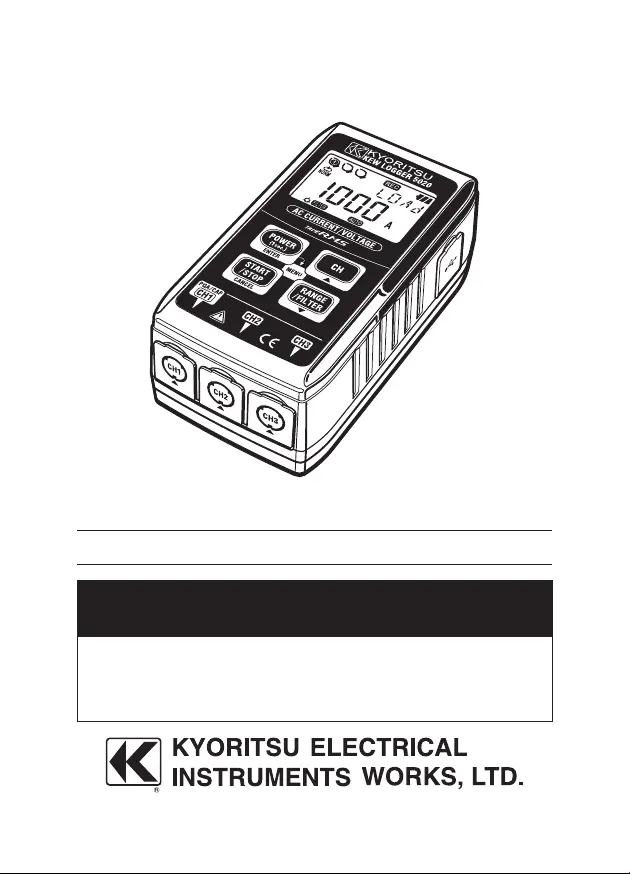
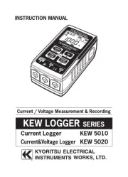
Kyoritsu KEW 5020 Manual
Kyoritsu
Måleudstyr
KEW 5020
Læs gratis den danske manual til Kyoritsu KEW 5020 (56 sider) i kategorien Måleudstyr. Denne vejledning er vurderet som hjælpsom af 12 personer og har en gennemsnitlig bedømmelse på 4.4 stjerner ud af 6.5 anmeldelser. Har du et spørgsmål om Kyoritsu KEW 5020, eller vil du spørge andre brugere om produktet?
Side 1/56

INSTRUCTION MANUAL
KEW LOGGER
SERIES
Current Logger KEW 5010
Current&Voltage Logger
KEW 5020
Current / Voltage Measurement & Recording

Introduction
Thank you for purchasing KEW LOGGER 5010/5020.
◦
Follow the procedure below and set time on the instrument before use.
1) Install the KEW LOG SOFT 2 and the USB Driver according to the
instructions written in the Install Manual for KEW LOG Soft 2.
2) Run KEW LOG SOFT 2 once install is completed. (Refer to
4. Start
KEW LOG SOFT 2
in the Install Manual.)
3) Confirm that the LOGGER and a PC is firmly connected with a USB
Cable and click
Time Synchronizing
.
4) Confirm that the Logger connected with the PC is listed on the
List of detected loggers
. (The USB Driver might not be installed
correctly when a message
No Logger is detected.
is displayed.
Refer to the backside of the
Cautions for installing USB Driver
install
or
6. Trouble shooting
of the Install Manual and re-install
the USB Driver.)
5) Click
Time Synchronizing
Button while the LOGGER is powered on
and checks are marked in the box for each connected LOGGER to
set time.
◦
Read this manual and do your desirable settings. (Setting should be done
by using
KEW LOG Soft 2
. Settings for some Recording modes can be
done on the LOGGER.
◦
Read through
1. Safety Warnings
in this manual before using the
LOGGER in order to ensure safe operation of the instrument.

Contents
1. Safety warnings
…………………………………………………………
1
2. Features
…………………………………………………………………
4
3. Instrument layout
………………………………………………………
5
3-1) Panel
………………………………………………………………
5
3-2) LCD
…………………………………………………………………
5
3-3) Displayed message
………………………………………………
7
3-4) Function of Button
…………………………………………………
8
3-5) Range/ Filter function
……………………………………………
9
4. Recording procedures
…………………………………………………
10
Step1: Start-up
………………………………………………………
11
Step2: Confirmation of set value
……………………………………
12
Step3: Preparation before a recording
………………………………
13
Step4: Start of recording
……………………………………………
15
Step5: Stop of recording
………………………………………………
17
5. Recording modes and conditions
………………………………………
18
Normal recording mode
………………………………………………
19
Trigger recording mode
………………………………………………
22
Capture recording mode
………………………………………………
24
Power Quality Analysis mode (only 5020)
……………………………
24
6. Recording modes
………………………………………………………
25
Flashing Detection LED
…………………………………………………
28
7. Simplified Power Integration Function
…………………………………
31
(available on KEW LOG Soft 2)
8. Other settings (Setting2)
………………………………………………
34
9. Confirmation of recorded data (CALL)
…………………………………
39
10. Data transfer to PC
……………………………………………………
43
11. Battery replacement
……………………………………………………
45
12. Auto-power off Function & External power supply
……………………
46
13.Trouble-shooting
…………………………………………………………
47
14.Specification
……………………………………………………………
49

1
1. Safety Warnings
This instrument has been designed, manufactured and tested according to
IEC 61010: Safety requirements for Electronic Measuring apparatus, and
delivered in the best condition after passed the inspection. This instruction
manual contains warnings and safety rules which must be observed by
the user to ensure safe operation of the instrument and retain it in safe
condition. Therefore, read through these operating instructions before using
the instrument.
WARNING
◦
Read through and understand the instructions contained in this manual
before using the instrument.
◦
Keep the manual at hand to enable quick reference whenever necessary.
◦
The instrument is to be used only in its intended applications.
◦
Read this full instruction manual which contains full details on this
instrument first, and then use the quick manual as a handy reference.
◦
To ensure safe operation of the instrument and clamp sensors, please
carefully read the instruction manual for the clamp sensor.
◦
Understand and follow all the safety instructions contained in the manual.
Failure to follow the instructions may cause injury, instrument damage and/
or damage to equipment under test. Kyoritsu is by no means liable for any
damage resulting from the instrument in contradiction to this cautionary
note.
The symbol indicated on the instrument means that the user must refer to the
related parts in the manual for safe operation of the instrument. It is essential to
read the instructions wherever the symbol appears in the manual.
DANGER is reserved for conditions and actions that are likely
to cause serious or fatal injury.
WARNING is reserved for conditions and actions that can cause
serious or fatal injury.
CAUTION is reserved for conditions and actions that can cause
injury or instrument damage.
DANGER
◦
Never make measurement on a circuit in which voltage over AC300V
exists.
◦
Do not make measurement while thunder is rumbling. Stop
measurement immediately and disconnect the instrument from the
object under test.
◦
Do not attempt to make measurement in the presence of flammable
gasses. Otherwise, the use of the instrument may cause sparking, which
can lead to an explosion.

2
◦
Transformer jaw tips are designed not to short the circuit under test.
If equipment under test has exposed conductive parts, however, extra
precaution should be taken to minimize the possibility of shorting.
◦
Never attempt to use the instrument if its surface or your hand is wet.
◦
Do not exceed the maximum allowable input of any measuring range.
◦
Never open the Battery Cover during a measurement.
◦
Verify proper operation on a known source before use or taking action
as a result of the indication of the device.
◦
Use only the voltage test leads supplied with the instrument.
◦
Connect to the measurement line only after connecting the instrument
and the voltage test leads.
◦
Always connect the voltage test leads to the secondary side of a circuit
breaker; the primary side may have large current capacity and may
cause danger.
◦
Use the clamp sensors dedicated to this instrument.
◦
Connect to the measurement line only after connecting the instrument
and the test leads.
◦
Do not touch two measurement lines at the same time, when opening
the jaws, with the metal part.
WARNING
◦
Never attempt to make measurement if any abnormal conditions, such
as broken case and exposed metal parts are found on the instrument.
◦
Do not install substitute parts or make any modification to the
instrument. For repair or re-calibration, return the instrument to your
local KEW distributor from where it was purchased.
◦
Do not try to replace the batteries if the surface of the instrument is wet.
◦
Disconnect all the cords and cables from the object under test and
power off the instrument before opening the Battery Cover for Battery
replacement.
◦
Stop using the test lead if the outer jacket is damaged and the inner
metal or color jacket is exposed.
CAUTION
◦
Put the instrument on a stable place where is free from vibrations or shocks.
◦
Keep away Floppy Disks, Mag Cards, PCs and Displays from the
magnet, which is attached to the backside of the instrument.
◦
Do not expose the instrument to the direct sun, high temperature and
humidity or dewfall.
◦
Be sure to power off the instrument after use. When the instrument will not
be in use for a long period, place it in storage after removing the batteries.
◦
Use a cloth dipped in water or neutral detergent for cleaning the
instrument. Do not use abrasives or solvents.
◦
Keep your fingers and hands behind the protective fingerguard during
measurement.

3
Measurement categories (Over-voltage categories)
To ensure safe operation of measuring instruments, IEC 61010 establishes
safety standards for various electrical environments, categorized as O to
CAT IV, and called measurement categories.
Higher-numbered categories correspond to electrical environments with greater
momentary energy, so a measuring instrument designed for CAT III environments
can endure greater momentary energy than one designed for CAT II.
O : Circuits which are not directly connected to the mains power
supply.
CAT II : Primary electrical circuits of equipment connected to an AC
electrical outlet by a power cord.
CAT III : Primary electrical circuits of the equipment connected directly
to the distribution panel, and feeders from the distribution panel
to outlets.
CAT IV : The circuit from the service drop to the service entrance, and
to the power meter and primary overcurrent protection device
(distribution panel).
O: Device which is
not directly
connected to the
mains power supply
Safety symbols
Refer to the instructions in the manual.
▪
Indicates a Instrument with double or reinforced insulation
Indicates that this instrument can clamp on live bare conductors
when the voltage to be tested is below Circuit – Ground-to-Earth
voltage against the indicated Measurement Category.
〜
Indicates AC
Indicates DC
This instrument satisfies the marking requirement defined in the
WEEE Directive (2002/96/EC). This symbol indicates separate
collection for electrical and electronic equipment.

4
2. Features
◦
KEW 5020 is a Data Logger capable of measuring Leakage Current,
Load Current and Voltage. (KEW5010 is for measuring Leakage Current
and Load Current).
◦
Following sensors are used for measuring current & voltage.
* Leak/Load Current Clamp Sensor
* Load Current Clamp Sensor
* Voltage Sensor (for KEW5020)
◦
TRMS measurement & recording of AC Current (50/60Hz) & AC Voltage
(50/60Hz, only on KEW5020)
◦
LED to indicate pre-set current/ voltage value is exceeded.
(Trigger/ Capture Recording, Power Quality Analysis modes)
◦
Can store 60,000 data when using 1ch, and when using all 3ch, can
store 20,000 data at each channel. (Normal recording mode)
◦
Data will not be lost at battery replacement or at low battery voltage as it
is stored in nonvolatile memory.
◦
Long time recording is available by a use of external AC Adaptor
(optional parts) Installed batteries enables backup at a temporally
electricity failure. Size AA Alkaline Battery: about 10-day measurement.
◦
Can transfer the recorded data to PC via USB cable.
◦
Protected throughout by double (reinforced) insulation
▪
◦
This instrument provides 3 Recording modes and Power Quality Analysis
mode (only KEW5020). Various insulation monitoring are available with 4
recording modes. Understand characteristic of each recording mode and
select an appropriate mode.

5
◆
Detection LEDs P.28
◆
USB P.43
◆
Port for External power supply P.46
3. Instrument layout
3-1) Panel
3-2) LCD

6
Mark Details
Channel number (CH No.) : Selected Channel number
is displayed.
Memory Block Number : Memory block (No. 1 to
3) in use is indicated. (P.
39)
Sensor Mark : Displayed on the CH No. to Indicate the
connected Sensor.
Clock Mark : Indicates time
Timer Mark : Timer function is activated.
(Stand-by till the preset time.)
Recording Mark : Recording is being performed.
Auto-power-off is disabled.
(Instrument won't be off automatically.)
Battery Mark : Indicates battery voltage in 4-level
Recording mode
Sub-indication : Indicates Menu items
Date : Month, Day
Main indication : Displays measured, preset and
recording values
Guide mark : Items can be switched with /
button.
One-time : Recording stops when memory becomes full
Endless : Overwrite the old data, and store the latest data.
Range Hold/ Auto Range mark :
Status of the selected
Range
Filter mark : Indicates Filter function is activated.

7
3-3) Displayed message
Message Meaning
Sensor is not connected.
Over-range
Menu: Setting1 (SET.1)
P.18
View or change the recording mode/ condition.
Menu: Setting2 (SET.2)
P.34
View or change the Location information and
auto-power-off function.
Menu: Recall(CALL) P.39
Recorded qty., Max value reference, Recall
Normal recording mode
Trigger recording mode
Capture recording mode
Power Quality Analysis mode [KEW5020 only]
PC data in transit
Warning of memory clear
Error
(
improper Sensor is connected under
Power Quality Analysis mode/ KEW5020 only)
(P.47)
All the Memory block are occupied. (P.16)
Move the data and clear the memory. (P.34)
Sub-indication Sensor Type
Load current clamp sensor
Voltage Sensor
Leakage & Load current clamp sensor
Leakage current clamp sensor

8
3-4) Function of Button
Power ON / OFF
Menu mode
Recording/ Measurement mode
Button Power ON Power OFF
Pressing at least 1 sec
(while the LOGGER is off)
Pressing at least 1 sec
(except for recording status)
Button Function
Enter into Menu mode
Start and stop recording
Switch channels
Switch Range and Filter
Button Menu Setting Change (ashing)
Select Menu Setting change, Enter
Back Cancel
Switch Menu item Increase number
Switch Menu item Decrease number

9
3-5) Range/ Filter Function
●
Range Configuration
Range configuration varies depending on each connected Sensor.
Refer to "12. Specification" in this manual.
●
Auto-ranging
Auto-ranging is available only in Normal Recording mode. It isn't
available on a Sensor providing one single range.
(e.g. Voltage Sensor "KEW8309" for KEW5020)
●
Range Hold
Select the ranges with
mark to fix measurement range under
Normal Recording mode.
Measurement range in Trigger/ Capture Recording mode is decided
depending on a detection level. Switching of measurement ranges
with the button isn't possible.
●
Filter Function
Lowpass Filter works when Filter Function is ON
(
mark lights up
)
and filter out the frequency in higher harmonics band.
(Cutoff Frequency: approx 160Hz, attenuation rate -24dB)
●
Range/ Filter Function for each Recording mode
Recording mode Function
Normal recording
* Switching ranges, On/Off Filter
* Auto-ranging is available.
Trigger/ Capture
recording
* On/Off Filter
* Range corresponds to detection level
* Auto-ranging isn't available.
Power Quality Analysis
[KEW5020 only]
* On/Off Filter
* Auto-ranging isn't available.

10
Following explains the flow of operation: through preparation to the stop
of recording.
* The recorded data can be viewed either by the following two methods.
(1) On a PC: Follow the instruction described at "10. Data transfer to
PC" in this manual for data transfer, and Help for PC Software "KEW
LOG Soft 2" for operation method.
(2) On the instrument: Refer to "9. Confirmation of recorded data
(CALL)"
* Press the
button at least 1 sec. to power off the instrument.
(This is because to prevent operational error.)
4. Recording procedures
▼
Step1: Start-up
Step2: Confirmation of the set value
▼
Step3: Preparation before recording
▼
Step4: Start of recoding
▼
Step5: Stop of recording
Select the appropriate sensor, and
connect it to the instrument.
Conrm the recording mode.
Install the instrument and do setups for
each channel.
Start recording.
Stop recording.

11
1. Press the button and power off
the instrument. Connect a Clamp/
Voltage Sensor to CH1 (for multiple
connection, starting from CH1) while
the instrument is being off. Connect
them firmly with careful attention to the
orientation of the connector.
2. Press the button at least 1 sec.
to power on the instrument. Release
the button when all indications are
displayed on the LCD.
First, time is displayed, and then
sensors being connected are displayed.
If incorrect time is displayed whenever
powering on the instrument, internal
battery for clock may be exhausted. In
this case, send back the instrument to
your local KEW distributor for repair.
3. Check the connected Sensors.
Sensor and the full-scale value are
displayed.
(beginning from CH1)
◆
Sensor mark is displayed on the CH
No,. to which a Sensor is connected .
◆
Only CH1 is used in Capture REC mode.
◆
Voltage sensor is connected to CH1 in
PQA REC mode (only on KEW5020).
◆
Voltage sensor cannot be used with
KEW5010.
◆
Power off the instrument and repeat
steps from 1. to re-connect a Sensor.
▼
▼
▼
Step1: Start-up

12
4. Can make measurement right after
powering on the instrument.
* Each time pressing the
button,
CH1 to CH3 switches. When
(non-connect) is displayed on the
LCD, a sensor is not connected
to the selected channel; or the
connection is incorrect.
Check the mark indicating the selected
recording mode. Refer to
5. Recording
modes and conditions
in this manual
to change the recording mode or
condition (Recording interval / Preset
current)
Recording mode Details Refer to
Normal
Performs continuous measurement/
recording at the pre-set intervals.
(15-kind: 1 sec. to 60min.)
P.19
Trigger
Records 8 data (0.8 sec.) in total with
time information when pre-set detection
level is exceeded.
P.22
Capture
Records 10 (50Hz) to 12 waveforms
(60Hz) when preset detection level is
exceeded.
(Graph can be viewed on PC)
P.24
(PC setting)
Power Quality Analysis
(only 5020)
Records date and time information when
preset Swell, Dip and Short interruption
value are exceeded.
P.24
(PC setting)
Step2: Confirmation of preset value

13
1. Clamp on the measured object and fix
the Sensor. Firmly fix it so as not to
easily come off.
Care should be taken, when connecting
the Voltage Sensor designed only for
KEW5020, not to short the object
under test.
2. Fix the instrument.
1) Fix the instrument with magnet :
Can fix the instrument to metallic plate
with the magnet on its backside.
2) Hang the instrument on hook :
Can fix the instrument with a hook or
screw by using the hooking hole on the
top of the instrument.
(Firmly fix it so as not to easily come
off.)
3. Press the button to switch the
display of measured value among
CH1 to 3. Confirm a proper Sensor is
connected to an appropriate CH.
▼
▼
▼
Step3: Preparation before recording

14
4. Check a Range/ Filter
Press the
button to check their on/off
status.
Press the button to change them.
Independent setting of Range & Filter is
available on each CH.
Point
●
At Normal Recording mode, Range and
Filter switches each time pressing the
button.
Auto-ranging is also available.
●
At Trigger/Capture/Power Quality Analysis
modes, only Filter on/off is available.
Range is selected automatically based
on the detection level (preset value for
Trigger/ Capture Recording). See Setting1
"SEt.1".
●
Setting change isn't available during
recording; setting should be done prior to
a recording.
mark means Range Hold Function is
activated.
mark means Auto-ranging Function is
activated.
5. When only the leftmost segment of the
Battery mark is flashing on the LCD, it
means battery voltage is low.
Replace the batteries with new ones.
When nothing is displayed on the LCD,
the batteries are exhausted. Replace the
batteries with new ones.
▼

15
* Settings cannot be changed during recording. Carefully check the
settings prior to a recording.
* Previous recorded data is cleared and new recording starts when
changing the followings and starts recording. (In this case, "CLr" flashes on
the LCD at a start of recording.)
1) Recording mode is changed.
2) CH for Sensor is changed.
3) Sensor type is changed.
* Transfer important data to your PC first and clear Memory since further
recording isn't activated when all the 3 blocks in Memory Block see the next
page are full.
* Follow the procedure below to start recording.
1. Press down the
button at least 4 sec.
"
" or "CLr" mark flashes. Keep the button
pressed down until "
" mark lights up.
Recording stops when the button is released
while the mark is flashing.
2. Measured value is displayed and "
" mark
lights up, then measurement starts.
◆
Additional three recordings (Memory Block /
see the next page) are possible.
In this case, one-time is automatically selected
and recording stops when memory becomes
full.
◆
It is recommended to clear the memory before
starting to record if previous data is not
necessary.
Step4: Preparation before recording
↓
or

16
Memory Block
◆
One memory block is used from the start to the end of recording.
◆
3 blocks in the Memory Block are available; it enables 3 different
recordings at different locations.
◆
Transfer important data to your PC first and clear Memory (Setting 2
or via PC) since further recording isn't activated when all the 3 blocks
in Memory Block are used.
◆
Settable Location No. at Setting 2 "SEt.2" is saved in the Memory
Block together with the measured data; and is useful to recognize the
location where the data recorded on your PC.
◆
At Trigger/ Capture/ Power Quality Analysis modes, zero is saved in
Memory Block even when no data is recorded from the start to the end
of recording.
Operation during recording
Following operations are available during recording.
◆
Displaying the measured value at each CH
→
button
◆
Recording status : Displaying Max recorded valued & RECALL
Refer to 9. Confirmation of recorded data in this manual.
◆
Check of preset values at Setting 1"SEt.1" & Setting 2 "SEt.2".
Following operations aren't available during recording.
◆
Powering off the instrument
◆
Changing the measurement range.
◆
Change of preset values at Setting 1"SEt.1" & Setting 2 "SEt.2".
◆
Data communication with PC
Stop recording to do above operations.

17
In case that One-time is set to "ON" at Step2: Confirmation and change of
preset value, recording is stopped automatically when Memory becomes
full.
1. Press the button at least 1 sec
to stop recording.
2. Recording stops, and the "
" mark
disappears. Then the instrument
goes back into measurement state.
Now, recording completes.
* Press the button at least 1 sec to power off the instrument.
* It is recommended to transfer the important data to a PC.
* The recorded data can be checked on the instrument.
(Refer to : 9. Confirmation of recorded data (CALL) in this manual)
Step5: Stop of recording

18
* Recording mode and condition can be set on the instrument ; but PC
software "KEW LOG Soft 2" provides much easier setting.
* Only Normal and Trigger Recording modes can be set on the instrument.
Capture recording and Power Quality Analysis modes need to be set via a
PC. (Recording condition for the Capture Recording mode is changeable
on the instrument.)
●
Setting on the instrument (Menu Mode)
1. Power on the instrument, and press the
button
to enter into Menu Mode.
2. Select and set desirable recording mode and condition at "SEt.1 on the
Menu. Setting with the instrument is mentioned on the next page.
3. Press the
button at "End" on Menu Screen or press the
button and exit from the Menu Screen to return measurement status.
5. Recording modes and conditions
Each button acts as follows at Menu mode.
→
: Select, Change, Enter
→
: Return, Cancel
→
: Switch, Increase values
→
: Switch, Decrease values

19
Normal recording mode: Recording interval of 1min.
※
If input signals in the object under test vary significantly and frequently
during a measurement in normal recording mode, fixing a measurement
range is recommended.
Max. number of recorded data
Using all 3 channels Using 2 channels Using only 1 channel
20,000 data 30,000 data 60,000 data
Max. recording duration
Recording
interval
Using all 3 channels Using 2 channels Using only 1 channel
1 sec.
5:33:20 8:20:00 16:40:00
2 sec.
11:06:40 16:40:00 1 day / 9:20:00
5 sec.
1 day / 3:46:40 1 day /17:40:00 3 days/11:20:00
10 sec.
2 days/ 7:33:20 3 days/11:20:00 6 days/22:40:00
15 sec.
3 days/11:20:00 5 days/ 5:00:00 10 days/10:00:00
20 sec.
4 days/15:06:40 6 days/22:40:00 13 days/21:20:00
30 sec.
6 days/22:40:00 10 days/10:00:00 20 days/20:00:00
1 min.
13 days/21:20:00 20 days/20:00:00 41 days/16:00:00
2 min.
27 days/18:40:00 41 days/16:00:00 83 days/ 8:00:00
5 min.
69 days/10:40:00 104 days/ 4:00:00 208 days/ 8:00:00
10 min.
138 days/21:20:00 208 days/ 8:00:00 416 days/16:00:00
15 min.
208 days/ 8:00:00 260 days/10:00:00 520 days/ 0:00:00
20 min.
277 days/18:40:00 416 days/16:00:00 833 days/ 8:00:00
30 min.
416 days/16:00:00 625 days/ 0:00:00 1250 days/ 0:00:00
60 min. 833 days/ 8:00:00 1250 days/ 8:00:00 2500 days/ 0:00:00
* Max recording time is dependent on battery life (approx 10-day with size
AA Alkaline battery) Use of optional AC Adopter is recommended for long
time recording.
Setting items
Item Range for Setting Default
Recording interval
1,2,5,10,15,20,30 sec,
1,2,5,10,15,20,30,60min
1 min
One-time/ Endless One-time/ Endless Endless

20
Setting procedure
1. Power on the instrument, and press the
button. Then the instrument enters into
Menu mode.
2. Press the button when "SEt.1" is
displayed on the LCD.
3. Selected recording mode is displayed.
◆
When (Normal recording mode) is
displayed on the LCD, press the
button to proceed to the next setting.
◆
In case that , or is
displayed on the LCD, press the
button. Then the indication on the LCD
flashes.
Press the or button to
change it to
. Press the
button.
▼
▼
▼

21
4. Then recording interval is displayed.
Can be selected from; 1, 2, 5, 10, 15, 20, 30 sec.,
1, 2, 5, 10, 15, 20, 30, 60 min
◆
Press the button and proceed to the
next step when not changing the setting.
◆
To change the setting, press the
button. Then the indication on the LCD
flashes.
Press the or button to set
the value to the desired one. Then press the
button to confirm it.
5. Next, One-time/ Endless is indicated.
One-time: Recording stops when memory
becomes full.
Endless : Overwrite the old data, and store
the latest data.
◆
Press the
button and proceed to the
next step when not changing the setting.
◆
To change the setting, press the
button. Then the indication on the LCD
flashes.
Press the or button to set
the value to the desired one. Then press the
button to confirm it.
6. Now Setting 1 is complete; "End" is displayed on
the LCD. Press the button to return to
the screen on which "SEt.1" is displayed.
7. Press the button to get the instrument
ready for a measurement.
▼
▼

22
Max. number of recorded data
Setting items
Setting procedure
Using all 3 channels Using 2 channels Using only 1 channel
1,600 data 2,400 data 4,800 data
Item Range for Setting
Default
CH1 Detection Level
0 ~ 1000 (Unit depends on Sensor)
15
CH2 Detection Level
0 ~ 1000 (Unit depends on Sensor)
15
CH3 Detection Level
0 ~ 1000 (Unit depends on Sensor)
15
One-time/ Endless
One-time/ Endless
Endless
▼
▼
Trigger recording mode: Current set value of 15A
1. Connect a Sensor first prior to do setting.
When Sensor is not connected to the instrument
at setting, connect a Sensor, and then power
off once and on the instrument.
2. Press the
button while instrument is on to
enter into Menu mode.
3. Press the
button when "SEt.1" is
displayed on the LCD.
4. The selected recording mode is displayed.
◆
When (Trigger recording mode) is
displayed on the LCD, press the
button to proceed to the next setting.
◆
In case that
, or is displayed
on the LCD, press the button. Then
the indication on the LCD flashes. Press the
or button to change it to
. Press the button.
▼

23
5. Detection level at CH1 is indicated.
Can be set at every 1 from 0 to 1000
◆
To change the setting, press the button.
Then the indication on the LCD flashes.
◆
Press the or button to set the
value to the desired one. Then press the
button to confirm it.
◆
When using Leakage Current Sensor, pressing
the button at 1000mA indication
changes to 2A, pressing the button at
2A indication changes to 1000mA (1A)
Point
Further detection doesn't start when a value falls
to 50% or less (for voltage sensor: 1% or more)
of the detected level. Set the appropriate value
based on the test prior to recording.
6. Confirm or change the preset current value on
channel 2 and 3 as well.
7. Next, One-time/ Endless is indicated.
One-time: Recording stops when memory
becomes full.
Endless : Overwrite the old data, and store
the latest data.
◆
Press the
button and proceed to the
next step when not changing the setting.
◆
To change the setting, press the button.
Then the indication on the LCD flashes.
Press the or button to set
the value to the desired one. Then press the
button to confirm it.
▼
▼

24
8. Now Setting 1 is completed; "End" is displayed on
the LCD. Press the button to return to the
screen on which "SEt.1" is displayed.
9.
Press the
button to get the instrument ready
for a measurement.
Max number of recorded data
* Setting is available only on PC.
Using only 1 channel
345 data
Setting item
Max number of recorded data
* Setting is available only on PC.
Using only 1 channel
4000 data
Setting item
Capture recording mode: (Setting on PC)
Power Quality Analysis [only 5020] (Setting on PC)
Item Range for Setting Default
CH1 Detection Level 0 ~ 1000 15
One-time/ Endless One-time/ Endless Endless
Item
Range for Setting
Default
Reference Voltage (System Supply Voltage) 100V
〜
500V 100V
Swell Detection (Ratio against Reference Voltage)
100%
〜
200% 110% (110V)
Dip Detection (Ratio against Reference Voltage)
0%
〜
100% 90% (90V)
Short Interruption Detection
(Ratio against Reference Voltage)
0%
〜
100% 10% (10V)
Hysteresis (Ratio against Reference Voltage)
0%
〜
10% 1% (1V)
One-time/ Endless
One-time/ Endless
Endless

25
List of recording modes
6. Recording modes
Recoding mode
Normal
Recording
Trigger
Recording
Capture
recording
Power
QualityAnalysis
Details P.26 P.27 P.29 P.30
Application
Status/
Simplified
power monitor
Detection
of abnormal
current/
voltage
Check of
waveform
Detection of
abnormal voltage
variation(only
5020)
Can record:
60,000 data (1ch)
20,000 data (3ch)
4,800 data (1ch)
1,600 data (3ch)
345 data 4,000 data
Available CH 3 channels at the same time 1 channel only
Recording
Interval
15-kind: 1 sec. to
60 min.
−
Detection
Level
−
0 ~ 1000 (Unit depends on Sensor)
RMS measuring
interval
Approx. at every 0.1 sec.
Sampling
Cycle
Approx. 1.65mS/CH
Detection:
Approx. 0.55mS/
WaveformApprox.
1.1mS
Approx.
0.55mS
Sampling
Period
Always
Constantly until current
detection
Always
Record
timing
At every
interval
When the preset detection value is
exceeded.(irregular)
Measuringmethod
True RMS
Detection: Average value/ (convert the Peak
value (sine) to RMS)
Recording, Indication: True RMS
One-time
system
One-time: Recording stops when memory becomes full.
Endless: Overwrite the old data, and store the latest data.
Battery Life Approx. 10days

26
1. Normal Recording mode
●
Sampling period and RMS calculation
Sampling the inputs at every 1.6ms/CH and calculate the measured
value (RMS) at every 100ms. The Peak value (crest value in sampling
data) will be updated and kept.
●
Recording
Average of the measured value is recorded at every recording interval.
RMS measured values, Max, Min and Peak values (sampled crest
value converted to sine RMS value) are recorded at every 10 times of
recording.
●
Display of measured value
Average of RMS value is displayed on the LCD at every 1 sec.
(10 data)
※
If input signals in the object under test vary significantly and
frequently during a measurement in normal recording mode, fixing a
measurement range is recommended.

27
2. Trigger Recording mode
●
Detection and RMS value calculation
Sampling the inputs at every 1.6ms and comparing the Peak value
(sampled crest value converted to sine RMS value) and Detection level.
For current, when the Peak value exceeds the level and for voltage
when the Peak value is below the level; detection is triggered. RMS
value is calculated at every 100ms.
●
Recording
When the Detection level is exceeded, 8 data (for about 0.8 sec)
Including:
- 3 RMS values prior to the cross over point
- RMS value at the cross over point
- 4 RMS values subsequent to the cross over point
are recorded with time information. In case that events exceeding the
Detection level occur continuously, next detection doesn't start until it
drops to 50% or less of the detected value.
(for voltage, 5% or more than the detected value)
●
Display of measured value
Average of RMS value is displayed on the LCD at every 1 sec.
(10 data)

28
◆
Flashing Detection LED
●
LED on the Sensor connected channel blinks when following Trigger
is detected.
<On KEW5010> Trigger is detected when the measured values
exceed the pre-set detection level under Trigger/ Capture Recording
Mode.
<On KEW5020> Trigger is detected when the measured current
values exceed the pre-set detection level under Trigger/ Capture
Recording Mode and Power Quality Analysis Mode.
For voltage values, Trigger is detected when it is below the
detection level.
●
LED flashes whenever the measured values exceed the pre-set
detection level during measurements.
●
LED blinks every 4 sec during recordings after one detection
occurs. (When Auto-power off is OFF, it blinks every 2 sec.)
●
To restore the blinking LED during recordings, first press the
button once and enters into Menu mode. Then press the
button to return Measurement mode.

29
3. Capture Recording mode
●
Detection and RMS value calculation
Sampling the inputs at every 0.55ms only at CH1 and comparing the
Peak value (sampled crest value converted to sine RMS value) and
Detection level. For current, when the Peak value exceeds the level
and for voltage when the Peak value is below the level; detection is
triggered. RMS value is calculated at every 100ms.
●
Recording
When the preset current value is exceeded, instantaneous values
with corresponding time information are recorded for 200ms ( 10 or
12 waveforms) including 50ms prior to and subsequent to the cross
over point. In case that events exceeding the Detection level occur
continuously, next detection doesn't start until it drops to 50% or less
of the detected value. (for voltage, 5% or more than the detected
value)
●
Display of measured value
Average of RMS value is displayed on the LCD at every 1 sec.
(10 data)
(Waveform display is only available on PC. Use the enclosed Software
and transfer the data to your PC.)

30
4. Power Quality Analysis Mode (only 5020)
●
Detection and RMS value calculation
Sampling the inputs at every 0.55ms only at CH1 and comparing the
Peak value (sampled crest value converted to sine RMS value) at every
10ms and preset value to detect swell, dip and short interruption in
power supply. RMS value is calculated at every 100ms.
●
Recording
When swell, dip or short interruption is detected, the detected value is
recorded as Start (S) with time and date information.
In case that a input becomes close to the reference voltage by
hysteresis value, it is recorded as End (E) with time and date
information.
●
Display of measured value
Average of RMS value is displayed on the LCD at every 1 sec.
(10 data)

31
The PC software "KEW LOG Soft 2" provides easy calculation of integral
power consumption by use of current and voltage (only on KEW5020)
recorded under Normal Recording mode.
●
On KEW 5010, measures and records current values, and then enter
any voltage value and power factor on "KEW LOG Soft 2" to calculate
simplified power consumption.
●
On KEW 5020, simplified power calculation is available by using Voltage
and Current Sensors; apply any power factor to the recorded voltage and
current values via "KEW LOG Soft 2".
Calculation with any voltage value as same as KEW5010 is also possible.
Example of Connection
◆
Single-phase 2-wire (1
Φ
2W)
Model Name CH1 CH2 CH3
KEW LOG Soft2
Fixed parameters
KEW 5010 A --- --- Voltage value, Power factor
KEW 5020
A --- --- Voltage value, Power factor
V A --- Power factor
* Can be connected with 3 systems via each channel (1 through3).
7
. Simplified Power Integration
(available via KEW LOG Soft 2)

32
◆
Single-phase 3-wire (1
Φ
3W)
Model
Name
CH1 CH2 CH3
KEW LOG Soft2
Fixed parameters
KEW 5010 A1 A2 --- Voltage value, Power factor
KEW 5020
A1 A2 --- Voltage value, Power factor
V A1 A2 Power factor
◆
Three-phase 3-wire (3
Φ
3W)
General formula is: P=V
×
(A1
×
cos(30
°
-
Φ
1)+A2
×
cos(30
°
+
Φ
2)),
however, here
Φ
1=
Φ
2 is applied.
Therefore: P =
√
3/2
×
V
×
(A1+ A2)
×
PF
Model
Name
CH1 CH2 CH3
KEW LOG Soft2
Fixed parameters
KEW 5010 A1 A2 --- Voltage value, Power factor
KEW 5020
A1 A2 --- Voltage value, Power factor
V A1 A2 Power factor
L1
N
L2
A1VA2
SOURCE LOAD
SURCE LOAD
L1
L2
L3
A1VA2

33
◆
Three-phase 4-wire (3
Φ
4W)
Model
Name
CH1 CH2 CH3
KEW LOG Soft2
Fixed parameters
KEW 5010 A1 A2 A3 Voltage value, Power factor
KEW 5020 A1 A2 A3 Voltage value, Power factor
* Refer to "KEW LOG Soft 2- HELP" how to operate KEW LOG Soft 2.
The latest "KEW LOG Soft 2" can be downloaded from our web site.
www.kew-ltd.co.jp

34
●
Recording mode and condition can be set on the instrument; but PC
software "KEW LOG Soft 2" provides much easier setting.
●
Time setting for Year, Month, Day, Hour, Minute and Second is
available on PC, but setting for Hour and Minute only are available on
the instrument.
Menu Setting 2: "SEt.2" Setting items
1) Location information [Default:000]
Set the location no. to identify the measuring and recording place.
2) Auto-power-off [Default:000]
Enable/ Disable the Auto-power-off function.
3) Time
Capable of adjusting the time between 00:00 and 23:59.
4) Timer
[Default:OFF]
Display and set the timer.
5) Memory Clear
Clear all the recorded data.
8. Other settings (Setting2)
Each button acts as follows at Menu mode.
→
: Select, Change, Enter
→
: Return, Cancel
→
: Switch, Increase values
→
: Switch, Decrease values

35
Setting procedure
1. Power on the instrument, and press the
button.
2. Press the
button when "SEt.1" is displayed
on the LCD.
3. Press the button when "SEt.2" is displayed
on the LCD.
4. "Location information":
Location No. is displayed on the LCD.
Can be selected between "P.000" and "P.999".
◆
Press the button and proceed to the
next step (Auto-power-off) when not changing
the setting.
◆
To change the setting, press the
button.
Then the indication on the LCD flashes. Press
the or button to set the value
to the desired one. Then press the
button to confirm it.
Point
●
Preset Location No. is saved with a recorded
data (1 Memory Block). When performing
▼
▼
▼

36
additional recordings (up to 3 Memory Blocks),
it is recommended to set each Location No.
in advance. It is useful to identify the recorded
locations per Memory Block.
●
Location No. is linked to the Location list and
allows to display the Location name, which
corresponding to the Location No., when
displaying data on PC Software.
●
In case of setting Location no. on the
instrument, it is recommended to take notes of
the Location No. and the name.
5. "Auto-power-off":
State of Auto-power-off function is displayed.
On : Enables Auto-power-off function.
OFF : Disables Auto-power-off function.
◆
Press the button and proceed to the
next step (Time) when not changing the setting.
◆
To change the setting, press the button.
Then the indication on the LCD flashes. Press
the or button to set the value to
the desired one. Then press the button
to confirm it.
Point
"
" mark appears on the LCD when this
Function is "OFF". Power off the instrument after
use. Instrument powers off about 3 min after the
last Key operation when the Function is "ON".
LCD indication disappears during recording due
to Power Save Function while recording is being
performed.
▼
▼

37
6. "Time": Time is displayed.
Can be adjusted between "00:00" and "23:59".
◆
Press the
button and proceed to the
next step (Timer) when not changing the setting.
◆
To change the setting, press the button.
Then the indication on the LCD flashes.
Press the or button to set the
value to the desired one. Then press the
button to confirm it.
Point
Connect the instrument to PC and set time and
date via PC software : "KEW LOG Soft 2".
7. "Timer": State of Timer function is displayed.
Can be set between "00:00" and "23:59".
◆
Press the button and proceed to the
next step (Memory Clear) when not changing the
setting.
◆
To change the setting, press the
button.
Then the indication on the LCD flashes.
Press the
or button to set
the value to the desired one. Then press the
button to confirm it.
Point
Press the button at least 1 sec.
after setting Timer. Then the instrument goes into
stand-by mode for recording.
Recording starts at the preset time.
▼
▼

38
8. "Memory Clear": Clear the recorded data.
◆
Press the button to end Setting 2 when
you don't clear the Memory.
◆
Pressing the button flashes the
indication on the LCD.
Recorded data isn't deleted by pressing the
button, while "no" is displayed on the
LCD. Press the button to change the
indication to "CLr", and then press the
button to clear the recorded data. Message "O
DATA" is indicated and back to "CLr" indication
when data is cleared.
9. Now Setting 2 is completed; "End" is displayed on
the LCD. Press the button to return the
screen on which "SEt.2" is displayed.
10. Press the button to get the instrument
ready for a measurement.
▼
▼

40
3. Press the Button while "CALL" is displayed
on the LCD.
4. Check of <Recorded qty.>
Percentage of recorded data against memory
capacity is displayed.
* Memory block with recorded data is indicated
by the Marks:
❶❷❸
. When all 3 marks are lit
up, all the Memory blocks are used. Transfer the
important data to a PC and clear the Memory to
perform next recording.
Pressing the
Button proceeds to the
next.
5. Display of the number of the recorded data at
CH1/ the number of detected current & voltage
data in case of Trigger Recording mode.
◆
Pressing Button moves to CH2.
◆
Press the
Button to check max, min
and peak values on CH1 with time and date
information. See the next page <<MAX, MIN,
Instant PEAK/ detected value>>.
◆
Press the
Button until the indication
becomes "5:RCL" for RECALL and proceed to
step 8.
▼
▼
▼

41
6. Display of the number of the recorded data at
CH2/ the number of detected current & voltage
data in case of Trigger Recording mode.
Pressing the Button moves to CH3.
◆
Press the Button to check max, min
and peak values with time and date information.
See the next page <<MAX, MIN, Instant PEAK/
detected value>>.
7. Display of the number of the recorded data at
CH3/ the number of detected current & voltage
data in case of Trigger Recording Mode.
Pressing the Button moves to "RECALL".
◆
Press the Button to check max,
min and peak values with time and date
information. See the next page <<MAX, MIN,
Instant PEAK/ detected value>>.
8. <RECALL> checks the latest 10 recorded data.
Press the Button to check the latest
recorded data and preceding 9 data, [R01] to
[R10]. Refer to next page <<RECALL>>
9. That's all for CALL Function to call the recorded
data. Pressing the Button returns to
the window with "CALL" message; pressing the
Button closes Menu mode and gets ready
for measurement.
▼
▼
▼

43
●
Install PC software "KEW LOG Soft 2" on your PC to enable data
communication between the instrument and your PC. Refer to the
HELP contained in "KEW LOG Soft 2" which shows how to install the
software. It will be on the Desktop after installing the software, or
found in the folder of "KEW" from "Start"
→
"Program".
●
When connecting the logger to PC for the first time, your PC will
recognize this new hardware and install the USB driver.
Follow the instructions described in the instruction manual for "KEW
LOG Soft 2" and install it on your PC.
10-1 Connection of USB cable
(1) Connect the USB cable to the available USB port of PC.
(2) Connect the other end of USB cable to the USB terminal on the
right side of this instrument.
10. Data transfer to PC
Note:
Remove the protective cover
of USB terminal carefully, and
connect a cable to it. When the
cover is damaged, it may cause
poor contact due to dust, etc.

44
10-2 Preparation for data transmission
(1) Power on the instrument, and get the instrument ready for a
measurement.
( Note: Data cannot be transferred while the instrument is
performing a recording.)
(2) Start up the PC software: KEW LOG Soft 2.
10-3 Operation of PC software
Refer to the supplied instruction manual for "KEW LOG Soft 2" or
"Help" and transfer the data to your PC. The PC may not detect
the connected Logger or error message is displayed during data
transfer, even if the PC and the Logger are connected correctly
because of static electricity.
In this case, a message is displayed on the PC screen. Disconnect/
connect the USB cable once accordingly, and transfer the data
again.
10-4 Multiple connections
By using commercially available USB hub, multiple Loggers can be
connected to your PC.
◆
With PC software "KEW LOG Soft 2", the data can be transferred
to PC by selecting one Logger from the list of detected Logger.
You do not have to connect and disconnect a USB cable one by
one.
◆
Synchronization via
「
KEW LOG Soft 2
」
enables synchronized time
setting on multiple LOGGERs at once.

45
WARNING
◦
In order to avoid electrical shock, remove sensors from the instrument
when replacing batteries.
CAUTION
◦
Do not mix new and old batteries.
◦
Install batteries in the orientation as shown inside the battery
compartment, observing correct polarity.
When only the leftmost segment of the Battery mark
is flashing
on the LCD, it means battery voltage is low. Replace the batteries with
new ones. There is no influence on the measurement accuracy even
if this warning mark is flashing. Nothing even the Battery mark is
displayed on the LCD if the batteries are completely exhausted.
Replace the batteries with new ones.
(1) Loosen two Battery-cover -fixing
screws on the backside of the
instrument and remove the cover.
(2) Replace the batteries with new
ones.
(Battery : Alkaline, LR6, 1.5V)
(3) Install the Battery cover, and
tighten up the screws.
11. Battery replacement

46
1) Auto-power off Function
LOGGER is automatically powered off in about 3 min after the last
key operation while Auto-power off Function is "ON" at Setting 2. This
function doesn't work during recording (LCD with
mark
)
although
readings aren't displayed on the LCD due to Power-saving Function.
In case of using an external power supply for making measurement,
disable the Auto-power off Function. Then long period measurement is
possible. (Be sure to power off the LOGEER after use.)
2) External power supply AC Adopter (optional)
WARNING
◦
Use MODEL 8320 only.
◦
Use the Power cord supplied with the AC Adopter.
◦
Confirm the voltage of power supply and the rated voltage of the AC
Adopter, and then connect the Power Cord.
◦
Disconnect the Power cord of the AC Adopter from the outlet when the
LOGGER isn't used for a long period.
◦
Do not put any heating object or others on the AC Adopter or Power
Cord.
◦
Hold the Plug part (other than cord) when disconnecting the Power
Cord from the outlet in order to prevent a break in the cord.
Specification of AC Adopter
◦
Rated supply voltage, Frequency : AC100V / 240V,50/60Hz
◦
Supply voltage, Range of Frequency variation
: 90~264VAC,45~66Hz
◦
Rated output voltage of AC Adopter : DC9.0V
◦
Rated max Output current of AC Adopter : 1.4A
Use the optional AC Adopter for long period recordings. Installing batteries
in the Case located at the backside of the unit provides power at temporary
electricity failure. Be sure to check the battery level in advance.
Battery mark with full level will be displayed while using the AC Adaptor.
Disconnect the Adaptor to check the battery voltage level.
12.
Auto-power off Function & External Power Supply

47
When defect or breakdown of the instrument is suspected, check the
following points first. If your problem isn't listed in this section, contact your
local Kyoritsu distributor.
Symptom / Check
1. Unable to measure.(
is displayed.)
◦
Check if a sensor is connected to the properly.
◦
Insert the sensor into the connector terminal firmly.
◦
KEW 5010 doesn't recognize the voltage Sensor
2. Unable to measure. (
is displayed.)
◦
Sensor other than Voltage Sensor may be connected to CH1 under
the setting for Power Quality Analysis mode for KEW 5020.
◦
Only the Voltage Sensor can be used under Power Quality Analysis
mode.
3. Inaccurate readings
◦
Check if a clamp sensor is connected properly.Insert the sensor into
the connector terminal firmly.
◦
Check if the jaws are closed properly.
◦
Check if an object stick to the jaw tips.
4. Nothiing is displayed in the LCD
5. Battery symbol is blinked in the LCD.
6. The readings fluctuate.
◦
Check the battery voltage.
◦
If the voltage is low, replace the batteries.
13. Troubleshooting

48
7. When the logger is connected to the PC using the USB cable, the
logger connected is not detected in the logger list.
◦
Check if the USB cable is connected correctly.
◦
Check if the USB driver is installed.
◦
Check if the USB driver is failed to be installed on the PC.
◦
If the installation is failed, firstly delete the USB driver installed and
re-install it according to the procedure stated in the USB Notice sheet
or Install Manual.
8. When installing the USB driver with the hardware Windows, the following
remark appears.
◦
"The software you are installing for this hardware:
KEW LOGGER 5010/5020 has not passed Windows Logo testing to
verify its compatibility with Windows."
Click "Continue Anyway" to continue the installation.
As operation check was done, no problem shall happen.
(Windows
is a registered trademark of Microsoft of the United Sates.)

49
14. Specification
Measuring Range and Accuracy
<RMS accuracy>
(
AC 50/60Hz,Sine wave, Input: 10% or more of the range at CH1)
Range
KEW 8128 (5A) :5A/50A
KEW 8135 (50A) :50A
KEW 8146 (30A) :100.0mA/1000mA/10.00A/30.0A
KEW 8147 (70A) :100.0mA/1000mA/10.00A/70.0A
KEW 8148 (100A) :100.0mA/1000mA/10.00A/100.0A
KEW 8121 (100A) :10.00/100.0A
KEW 8122 (500A) :50.00/500.0A
KEW 8123 (1000A) :100.0/1000A
KEW8130 (1000A) :1000A
KEW 8309 (600V) :600.0V (only 5020)
Digit number
4-digit
Effective
InputRange
0% ~ 100% of each Range
Display Range
0% ~ 105% of each Range (
OL
is displayed over 105%.)
Accuracy
100.0mA Range:
±
2.0%rdg
±
0.9%f.s. + Accuracy of Sensor
Other ranges :
±
1.5%rdg
±
0.7%f.s. + Accuracy of Sensor
Crest
Factor
2.5 or less :RMS accuracy (sine) + 2%rdg+1%f.s.
(95% or less of each Range)
<Accuracy at Trigger Recording Mode
(
AC 50/60Hz sine wave)
Accuracy
100.0mA Range:
±
3.5%rdg
±
2.2%f.s. + Accuracy of Sensor
Other ranges :
±
3.0%rdg
±
2.0%f.s. + Accuracy of Sensor
<Accuracy at Capture/ Power Quality Analysis mode>
<Accuracy of instantaneous value at Capture Recording mode>
Accuracy
100.0mA Range:
±
3.0%rdg
±
1.7%f.s. + Accuracy of Sensor
Other ranges :
±
2.5%rdg
±
1.5%f.s. + Accuracy of Sensor

50
NOTE:
- Refer to the Instruction Manual attached to the Sensor for the specification of each
Sensor.
- Electromagnetic compatibility(EMC)
EN61000-4-2 Electrostatic discharge immunity(ESD) / Performance criteria: B
- Max, Min and Instant Peak values in Normal Recording mode are just reference
values; their accuracies aren't guaranteed.
◦
Operating system : Successive Approximation
(CH1 single synchronized sampling)
◦
Rated max. working voltage : AC9.9Vrms, 14V peak value
◦
Number of input channel : 3ch
◦
Measuring method : True RMS
◦
RMS measuring interval : approx. 100ms.
◦
Sampling interval
Normal/Trigger mode : approx. 1.65ms/CH
Capture mode : approx. 0.55ms (waveform: at every 1.1ms)
P.Q.A mode : approx. 0.55ms
◦
Display : Liquid crystal display
◦
Low battery warning : Battery mark display (in 4 levels)
◦
Over-range indication : "OL" mark is displayed when exceeding the
measuring range.
◦
Auto power off : Power-off function operates automatically after
a switch remains for 3min. (when recording is
stopped)
◦
Location for use : Indoor use, Altitude up to 2000m
◦
Temperature & humidity range(guaranteed accuracy):
23
℃±
5
℃
/ Relative humidity 85% or less (no
condensation)
◦
Operating temperature & humidity range:
-10
℃
~50
℃
/ Relative humidity 85% or less (no
condensation)
◦
Storage temperature & humidity range:
-20
℃
~60
℃
/ Relative humidity 85% or less (no
condensation)
◦
Battery : DC6V: Alkaline battery(LR6) x 4pcs
External supply DC9V (Special AC Adapter)
◦
Current consumption : approx. 10mA
◦
Possible measurement time
: Approx.10days (with alkaline LR6 batteries)

52
memo

6-22 92-1770E
DISTRIBUTOR
Kyoritsu reserves the rights to change specifications or designs
described in this manual without notice and without obligations.
Produkt Specifikationer
Mærke: | Kyoritsu |
Kategori: | Måleudstyr |
Model: | KEW 5020 |
Har du brug for hjælp?
Hvis du har brug for hjælp til Kyoritsu KEW 5020 stil et spørgsmål nedenfor, og andre brugere vil svare dig
Måleudstyr Kyoritsu Manualer
23 Februar 2025
2 September 2024
29 August 2024
29 August 2024
29 August 2024
29 August 2024
29 August 2024
29 August 2024
29 August 2024
29 August 2024
Måleudstyr Manualer
- Senseca
- Testboy
- Velleman
- GoClever
- MGL Avionics
- Water-i.d.
- Shimano
- Finder
- Be Cool
- Brookhuis
- P3 International
- Sauter
- Seaward
- Victron Energy
- SecuTech
Nyeste Måleudstyr Manualer
3 April 2025
3 April 2025
3 April 2025
3 April 2025
3 April 2025
3 April 2025
3 April 2025
3 April 2025
3 April 2025
3 April 2025