La Crosse Technology WS-7017U-IT Manual


Læs gratis den danske manual til La Crosse Technology WS-7017U-IT (9 sider) i kategorien Vejrstation. Denne vejledning er vurderet som hjælpsom af 53 personer og har en gennemsnitlig bedømmelse på 4.5 stjerner ud af 27 anmeldelser. Har du et spørgsmål om La Crosse Technology WS-7017U-IT, eller vil du spørge andre brugere om produktet?

Side 1/9
WS-7017U-IT
Wireless 915 MHz
Radio-Controlled Weather Station
Instruction Manual
FCC ID: OMOTX29U (transmitter)
RF Exposure mobile:
The internal / external antennas used for this mobile transmitter must
provide a separation distance of at least 20 cm (8 inches) from all
persons and must not be co-located or operating in conjunction with
any other antenna or transmitter.
Statement according to FCC part 15.19:
This device complies with Part 15 of the FCC Rules. Operation is subject
to the following two conditions: (1) this device may not cause harmful
interference, and (2) this device must accept any interference received,
including interference that may cause undesired operation.
Statement according to FCC part 15.21:
Modifications not expressly approved by this company could void the
user’s authority to operate the equipment.
Statement according to FCC part 15.105:
NOTE:
This equipment has been tested and found to comply with the
limits for a Class B digital device, pursuant to Part 15 of the FCC Rules.
These limits are designed to provide reasonable protection against
harmful interference in a residential installation. This equipment
generates, uses and can radiate radio frequency energy and, if not
installed and used in accordance with the instructions, may cause
harmful interference to radio communications.
However, there is no guarantee that interference will not occur in a
particular installation. If this equipment does cause harmful interference
to radio or television reception, which can be determined by turning
the equipment off and on, the user is encouraged to try to correct the
interference by one or more of the following measures:
Reorient or relocate the receiving antenna.
Increase the separation between the equipment and receiver.
Connect the equipment into an outlet on a circuit different from that
to which the receiver is connected.
Consult the dealer or an experienced radio/TV technician for help.
INVENTORY OF CONTENTS
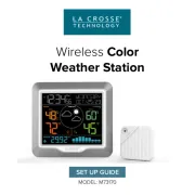
1. The Wireless Weather Station/ (Figure 1).
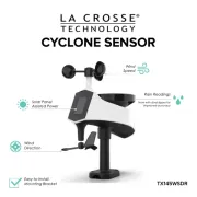
2. One remote temperature sensor with mounting bracket (Figure 2).
3. Three each, 1/2" Philips screws.
4. Instruction manual and warranty card.
ADDITIONAL EQUIPMENT (not included)
1. Two fresh AA 1.5V Alkaline batteries for the Wireless Weather
Station.
2. Two fresh AA 1.5V Alkaline batteries for the remote temperature
sensor.
3. One, Philips screwdriver for mounting.
ABOUT WWVB (Radio Controlled Time)
The NIST (National Institute of Standards and Technology-Time and
Frequency Division) WWVB radio station is located in Ft. Collins,
Colorado, and transmits the exact time and date signal continuously
throughout the United States at 60 kHz. The signal can be received up
TABLE OF CONTENTS
Topic Page
Inventory of Contents/Additional Equipment 3
About WWVB 3
Quick Set-Up Guide 4
Detailed Set-Up Guide 5
Battery installation 5
Program Mode
Program Sequence and Default Settings 7
Function Keys 7
Setting the LCD Contrast 7
Setting the Time Zone 8
Daylight Saving Time Setting 8
Radio-controlled Time Setting 9
12/24-hour Time Setting 9
Setting the Time 10
Setting the Year, Day and Month 11
Setting the Snooze 11
Setting the Temperature Format 11
Setting the Forecast Sensitivity 12
Features
Weather Forecast Icons and Tendency Arrows 13
Indoor Temperature, Humidity, & Comfort
Level Indicator 14
Outdoor Temperatures 14
Minimum & Maximum Records (Indoor,
Outdoor, & Resetting) 14
Additional Remote Control Sending Units
(Set-Up, Viewing, & Operation) 15
Mounting 17
Troubleshooting 19
Maintenance & Care 20
Specifications 20
Warranty Information 20
This product offers:
INSTANT TRANSMISSION
is the
st at e-of -the-ar t new wir eless
transmission technology, exclusively
designed and developed by LA
C R O S S E T E C H N O L O G Y.
INSTANT TRANSMISSION
offers you can an immediate update
(every 4 seconds!) of all your outdoor data measured from the
transmitters: follow your climatic variations in real-time!
GB P.2 GB
P.3
Figure 1
Time LCD
Date LCD
Forecast LCD
Indoor LCD
Outdoor LCD
Mounting
Bracket
TX29U-IT remote
temperature
sensor
Figure 2
SI Z E AA LR6
SI Z E AA LR6
to 2,000 miles away through the internal antenna in the Weather Station.
However, due to the nature of the Earth’s Ionosphere, reception is
very limited during daylight hours. The Weather Station will search for
a signal every night when reception is best. The WWVB radio station
derives its signal from the NIST Atomic clock in Boulder, Colorado. A
team of atomic physicists is continually measuring every second, of
every day, to an accuracy of ten billionths of a second per day. These
physicists have created an international standard, measuring a second
as 9,192,631,770 vibrations of a Cesium-133 atom in a vacuum. For
more information on the atomic clock and WWVB please see the NIST
website at http://www.boulder.nist.gov/timefreq/stations/wwvb.htm.
QUICK SET-UP GUIDE
Hint:
Use good quality Alkaline Batteries and avoid rechargeable
batteries.
1. Have the Wireless Weather Station and remote temperature sensor
3 to 5 feet apart.
2. Batteries should be out of both units for 10 minutes.
3. Place the batteries into the remote temperature sensor first then
into the Wireless Weather Station.
(All remote temperature sensors must be started before the Wireless
Weather Station)
4. DO NOT PRESS ANY BUTTONS FOR 15 MINUTES.
In this time the Wireless Weather Station and remote temperature
sensor will start to talk to each other and the display will show both the
indoor temperature and humidity, and an outdoor temperature. If the
Wireless Weather Station does not display both temperatures after the
15 minutes please retry the set up as stated above. After both indoor
and outdoor temperatures are displayed for 15 minutes you can place
your remote temperature sensor outdoor and set your time.
The remote temperature sensor should be placed in a dry, shaded
area. The temperature sensor has a range of 330 feet. Keep in mind
that the 330 feet is in open air with no obstructions and that radio
waves DO NOT curve around objects. Actual transmission range will
vary depending on what is in the path of the signal. Each obstruction
(roof, walls, floors, ceilings, thick trees, etc.) will effectively cut signal
range in half.
Example:
A Wireless Weather Station with a 330 feet range is mounted
on an interior wall, so that the signal has to pass through one interior
wall, one exterior wall, and across the 10 feet width of the room between
the 2 walls. The first wall will reduce the range to 165 feet, and the
second wall will reduce the range to 87 feet. Factoring in the 10 foot
room, this leaves a maximum of 77 feet of remaining signal range.
This allowance is typically enough for a frame wall with non-metallic
siding; however certain materials can reduce range even further. Metal
siding, stucco, and some types of glass can reduce signal range by as
much as 3/4 or more, compared to the 1/2 reduction typical of most
obstructions. It is possible to receive a signal through these materials,
however maximum range will be much less due to their tendency to
absorb or reflect a much larger portion of the sensor’s signal.
To complete the set up of your Wireless Weather Station after the 15
minutes have passed please follow the steps that follow in the Detailed
Set-Up Guide.
DETAILED SET-UP GUIDE
I. BATTERY INSTALLATION
(When one temperature sensor is being used)
1. First, insert the batteries to the temperature sensor (see A. Remote
Temperature Sensor” below).
2. Within 30 seconds of powering up the sensor, insert the batteries
to the Weather Station (see
B. Wireless Weather Station
” below).
Once the batteries are in place, all segments of the LCD will light
up briefly. Following the indoor temperature and humidity, and the
time as 12:00 will be displayed. If they are not shown in LCD after
60 seconds, remove the batteries and wait for at least 60 seconds
before reinserting them. Once the indoor data is displayed user
may proceed to the next step.
3. After the batteries are inserted, the Weather Station will start
receiving data signal from the sensor. The outdoor temperature
should then be displayed on the Weather Station. If this does not
happen after 2 minutes, the batteries will need to be removed from
both units and reset from step 1 and the signal reception icon is no
longer shown.
A. REMOTE TEMPERATURE SENSOR
1. Remove the mounting bracket. The bracket snaps on and off easily.
GB P.4 GB
P.5
Battery Cover
2. Remove the battery cover, by sliding the cover down.
3. Observing the correct polarity install 2 AA batteries. The batteries
will fit tightly (to avoid start-up problems make sure they do not
spring free).
4. Replace the battery cover by sliding upwards. Be sure battery cover
is on securely.
B. WIRELESS WEATHER STATION
1. Remove the battery cover. To do this, insert a solid object in the
space provided at the lower-central position of the battery cover,
then push up and pull out on the battery cover.
2. Observe the correct polarity, and install 2 AA batteries.
3. Replace the battery cover.
* When the signal is successfully received by the Weather Station,
the icon will be switched on. (If not successful, the icon will not be
shown in LCD) So the user can easily see whether the last reception
was successful (icon on) or not (icon off). On the other hand, the
short blinking of the icon shows that a reception is being done now.
If the signal reception is not successful on the first frequency
(915MHz) for 45 seconds, the frequency is changed to 920MHz
and the learning is tried another 45 seconds. If still not successful
the reception is tried for 45 seconds on 910MHz. This will also be
done for re-synchronization.
PROGRAM MODE
Programming Note: If 30 seconds is allowed to pass, or the CH button
is pressed during the programming mode, the unit will confirm/set the
last information entered-the display will stop flashing and return to
normal time-date readings. If you don’t leave the program mode during
the programming of sections III through XII, you can advance to step 4
of the next program setting. If you do leave the program setting (or
want to program a specific setting) follow each instructional step to
program that setting.
I. PROGRAMMING SEQUENCE AND DEFAULT SETTINGS
The programming sequence and default (factory) settings are as
follows:
LCD Contrast 5
Time Zone -5 (Eastern)
Daylight Saving Time 1 (on)
Radio-controlled time receptionON
12/24-hour time 12
Time 12:00
Year 2006
Day and Month 1.1.
Snooze (this function not used) 10
Temperature Format ˚F
Forecast Sensitivity 2
Please note that while there is a snooze adjustment in the programming
this is an unused function as there is no alarm on the Wireless Weather
Station.
II. FUNCTION KEYS
The function keys are located on the front of the unit directly below the
LCD.
III. SETTING THE LCD CONTRAST
1. Press and hold the SET button for 5 seconds.
2. “LCD” will show in the time LCD and the number setting will flash.
Note:
There are 8 LCD contrast levels to choose from-”Lcd 0" is the
lightest, and “Lcd 7” is the darkest.
GB P.6 GB
P.7
Battery Cover
Sensor signal
reception icon*
3. Press and release the IN button to select the level you desire.
4. Press and release the SET button to confirm and advance to the
Time Zone setting.
IV. TIME ZONE SETTING
1. Press and hold the SET button for 5 seconds.
2. “LCD” will show in the time LCD and the number setting will flash.
3. Press and release the SET button again.
4. The time zone will flash in the date LCD.
5. Press and release the IN button to select your time zone.
Note:
When a time zone for the U.S. is selected the corresponding
abbreviation will appear above the time (please see the table on the
next page). It is possible to select any time zone from -12 GMT to +12
GMT (for example to see the time in another country)
TIME ZONES
GMT 0
ALT Atlantic -4
EST Eastern -5
CST Central -6
MST Mountain -7
PST Pacific -8
ALA Alaska -9
HAW Hawaii -10
6. Press and release the SET button to confirm and advance to the
Daylight Saving Time setting.
V. DAYLIGHT SAVING TIME (DST) SETTING
1. Press and hold the SET button for 5 seconds.
2. “LCD” will show in the time LCD and the number setting will flash.
3. Press and release the SET button twice.
4. “DST” will appear in the date LCD and either “1” or “0” will flash.
5. Press and release the IN button to select DST on or off.
“DST 0” indicates that the feature is off and the WWVB will not change
times automatically. “DST 1” indicates that the feature is on and the
WWVB will change times automatically.
Note:
Some locations (Arizona and Hawaii) do not follow Daylight
Saving Time, and should select “DST 0.
6. Press and release the SET button to confirm and advance to the
radio-controlled time on/off setting.
VI. RADIO-CONTROLLED TIME ON/OFF SETTING
1. Press and hold the SET button for 5 seconds.
2. “LCD” will show in the time LCD and the number setting will flash.
3. Press and release the SET button 3 times.
4. “RCC” will appear in the date LCD and “ON” or “OFF” will flash in
the time LCD.
5. Press and release the IN button to select radio-controlled time on
or off.
6. Press and release the SET button to confirm and advance to the
12/24-hour time setting.
VII. 12 OR 24 HOUR TIME SETTING
1. Press and hold the SET button for 5 seconds.
2. “LCD” will show in the time LCD and the number setting will flash.
3. Press and release the SET button 4 times.
4. “12h” or “24h” will flash in the time LCD.
5. Press and release the IN button to select 12 or 24-hour time format.
GB P.8 GB
P.9
Note:
When in the 12-hour format “P.M.” will appear to the left of the
hour in the time LCD between the hours of noon and midnight.
6. Press and release the SET button to confirm and advance to the
time setting.
VIII. TIME SETTING
There are two methods by which the time and date can be set:
A. Automatically via WWVB reception, or
B. Manually.
A. WWVB (Remote Control Time)
This method requires you to do nothing, except wait for the signal to be
received, and to select a time zone. Reception usually takes
approximately 10 minutes during optimal conditions. The best condition
for reception is at night, between midnight and 6:00 am-when there is
less atmospheric interference. To keep your time as accurate as
possible, Wireless Weather Station conducts a WWVB search every
night between these hours, and overrides any manually set time. The
WWVB tower icon (appearing in the TIME LCD) will flash when a signal-
search is in progress and a signal is being received, and will remain
steady when the signal has been received. If the WWVB time has not
been received after 10 minutes of battery installation, you may manually
set the time or leave the time function alone (reception will occur
regardless). After a successful reception, no more reception attempt
would be made until the following day.
B. MANUAL TIME SETTING
Note:
When in the 12-hour format “P.M.” will appear to the left of the
hour in the time LCD between the hours of noon and midnight.
1. Press and hold the SET button for 5 seconds.
2. “LCD” will show in the time LCD and the number setting will flash.
3. Press and release the SET button 5 times.
4. The time will flash in the time LCD.
5. Press and release the IN button to advance the hours.
6. Press and release the OUT button to advance the minutes.
7. Press and release the SET button to confirm and advance to the
year setting.
IX. SETTING THE YEAR, DAY AND MONTH
Note:
Reception of the WWVB signal will also set the date and day.
The reception of the signal will override any programmed date and
day.
1. Press and hold the SET button for 5 seconds.
2. “LCD” will show in the time LCD and the number setting will flash.
3. Press and release the SET button 6 times.
4. The year will flash in the date LCD.
5. Press and release the IN button to advance the year.
6. Press and release the SET button to confirm and advance to the
day/month setting.
7. The day and month will flash in the date LCD.
8. Press and release the IN button to advance the month.
9. Press and release the OUT button to advance the day.
10.Press and release the SET button to confirm and advance to the
snooze setting.
X. SETTING THE SNOOZE
Note:
This is an unused function of the Wireless Weather Station and
should be disregarded. The setting has no bearing on the operation.
Please press and release the SET button to advance to select the
temperature format.
XI. SELECTING ˚F OR ˚C
1. Press and hold the SET button for 5 seconds.
2. “LCD” will show in the time LCD and the number setting will flash.
3. Press and release the SET button 9 times.
4. Either “˚F” or “˚C” will flash in the time LCD.
5. Press and release the IN button to select the temperature format.
6. Press and release the SET button to confirm and advance to the
forecast sensitivity setting.
GB P.10 GB
P.11
XII. SETTING THE FORECAST SENSITIVITY
Note:
The forecast sensitivity can be adjusted to allow for areas that
have a higher or lower sensitivity to changing air pressure (for example
coastal areas have more pressure change than areas such as southern
Arizona).
The numbers correspond to the amount of air pressure change
necessary to trigger a change in the forecast icon. Areas that tend to
have more air pressure change would set the sensitivity to 3, while
areas that experience lower than normal air pressure change would
set the sensitivity to 1.
1. Press and hold the SET button for 5 seconds.
2. “LCD” will show in the time LCD and the number setting will flash.
3. Press and release the SET button 10 times.
4. Either “1”, “2” or “3” will flash in the time LCD.
5. Press and release the IN button to select the forecast sensitivity
6. Press and release the SET button to confirm the forecast sensitivity
and complete the programming.
FEATURES OF THE WS-7017U-IT
I. WEATHER FORECAST
The weather forecasting feature is estimated to be 75% accurate and
is for the upcoming 12 to 24 hours. The weather forecast is based
solely upon the change of air pressure over time. The WS-7017U-IT
averages past air-pressure readings to provide an accurate forecast-
creating a necessity to disregard all weather forecasting for 12-24 hours
after the unit has been set-up, reset, or moved from one altitude to
another (i.e. from one floor of a building to another floor). In areas
where the weather is not largely affected by the change of air pressure,
the sensitivity setting should be set to 1.
A. WEATHER ICONS
There are 3 possible weather icons that will be displayed in the
FORECAST LCD:
Sunny-indicates that the weather is expected to improve (not that the
weather will be sunny).
Sun with Clouds-indicates that the weather is expected to be fair (not
that the weather will be sunny with clouds).
Clouds with Rain-indicates that the weather is expected to get worse
(not that the weather will be rainy).
These icons indicate the expected weather change in the next 12 to
24 hours. The icon does not give an exact prediction of the weather,
however it should be viewed as a generalization of the expected weather
change (for example a “sunny” icon indicates the weather is expected
to improve).
The weather icons change when the unit detects a change in air
pressure. The icons change in order, from “sunny” to “partly sunny” to
“cloudy” or the reverse. It will not change from “sunny” directly to “rainy”,
although it is possible for the change to occur quickly. If the symbols
do not change then the weather has not changed, or the change has
been slow and gradual.
B. WEATHER TENDENCY ARROWS
Other possible displays in the FORECAST LCD are 2 weather tendency
arrows, one that points up (on the left side of the LCD) and one that
points down (on the right side of the LCD). These arrows reflect current
changes in the air pressure. An arrow pointing up indicates that the
GB P.12 GB
P.13
WWVB Tower Icon
(indicates time reception)
Weather Tendency Arrow
Remote Sensor
Number (Up to 3
Total)
Forecast Icon
Comfort Level
Indicator
Satellite Icon
(indicates outdoor
transmission)
air pressure is increasing and the weather is expected to improve or
remain good, an arrow pointing down indicates that the air pressure is
decreasing and the weather is expected to become worse or remain
poor.
II. INDOOR TEMPERATURE, HUMIDITY, AND COMFORT LEVEL
INDICATOR
The current indoor temperature (viewed on the left) and relative humidity
(viewed on the right) are displayed in the INDOOR LCD. The comfort
level indicator is located at the center of the INDOOR LCD. The indicator
will display a happy face icon when the temperature is between 68˚F
and 7F (20˚C and 25.9˚C), and the humidity is between 45% and
65%. A sad face icon will be displayed when the temperature and
humidity are outside the mentioned ranges.
III. OUTDOOR TEMPERATURE
The temperature received from the remote temperature sensor is viewed
in the OUTDOOR LCD. When there is more than one remote
temperature sensor unit in operation, a “boxed” number will appear to
the right of the temperature. This indicates which remote temperature
sensor unit (1, 2, or 3) is currently displaying its data in the OUTDOOR
LCD. (This feature is explained in fur ther detail in section V-Adding
Remote Temperature Sensors).
IV. MINIMUM AND MAXIMUM TEMPERATURE RECORDS
The WS-7017U-IT keeps a record of the MINIMUM and MAXIMUM
temperature, and the time and date of their occurrence-for both the
indoor and outdoor modes.
A. VIEWING THE INDOOR TEMPERATURE AND HUMIDITY
RECORDS
1. Press the IN button once. MIN appears above the indoor
temperature and the LCD will flash, indicating that the minimum
temperature and humidity, and the time and date of occurrence of
the indoor temperature are displayed. The minimum records will
display for 30 seconds before returning to the normal display mode.
2. Press the IN button again (once while “MIN” is still displayed, twice
otherwise). “MAX” appears above the indoor temperature and the
LCD will flash, indicating that the maximum temperature and
humidity, and the time and date of occurrence of the indoor
temperature are displayed.
3. While “MAX” is still displayed press the IN button again to return to
the current data display. Or you can wait 30 seconds, during either
the minimum or the maximum readings, and t he unit will
automatically return to current data readings.
B. VIEWING THE OUTDOOR TEMPERATURE RECORDS
1. Press the OUT button once. “MIN” appears above the outdoor
temperature and the LCD will flash, indicating that the minimum
temperature, and the time and date of occurrence are displayed.
The minimum records will display for 30 seconds before returning
to the normal display mode.
2. Press the OUT button again (once while “MINis still displayed,
twice otherwise). “MAX” appears above the outdoor temperature
and the LCD will flash, indicating that the maximum temperature
and the time and date of occurrence are displayed.
3. While “MAX” is still displayed press the OUT button again to return
to the current data display. Or you can wait 30 seconds, during
either the minimum or the maximum readings, and the unit will
automatically return to current data readings.
C. RESETTING THE MIMIMUM AND MAXIMUM RECORDS
1. All the indoor records (minimum and maximum) will be reset after
the IN button is pressed and held for 5 seconds.
2. All the outdoor records (minimum and maximum) will be reset after
the OUT button is pressed and held for 5 seconds.
V. ADDING REMOTE TEMPERATURE SENSORS (OPTIONAL)
The WS-7017U-IT is able to receive signals from 2 additional
temperature sensors. The following are instructions for the set-up of
temperature sensor units with the WS-7017U-IT. These extra sensors
can be purchased through the same dealer as this unit.
1. Remove all the batteries from the receiver and sensor(s) and wait
60 seconds. During these 60 seconds, press any button 20 times
to discharge any excess power.
2. Insert the batteries to the first temperature sensor.
3. Within 30 seconds of powering up the first sensor, insert the
batteries to the Weather Station. Once the batteries are in place,
all segments of the LCD will light up briefly. Following this the indoor
temperature and indoor humidity, time as 12:00, calendar, and
GB P.14 GB
P.15


Produkt Specifikationer

Mærke: La Crosse Technology
Kategori: Vejrstation
Model: WS-7017U-IT

Har du brug for hjælp?

Hvis du har brug for hjælp til La Crosse Technology WS-7017U-IT stil et spørgsmål nedenfor, og andre brugere vil svare dig