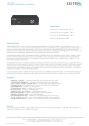
Listen D10-1-Dante Manual


Læs nedenfor 📖 manual på dansk for Listen D10-1-Dante (48 sider) i kategorien Ikke kategoriseret. Denne guide var nyttig for 19 personer og blev bedømt med 4.8 stjerner i gennemsnit af 10 brugere

Side 1/48
D Series
Installation Handbook
& User Guide
www.ampetronic.co
Ampetronic D Series Installation Handbook & User Guide Page 1
CONTENTS
Contents ..........................................................1
1. Safety & Box Contents ...............................................2
2. Introduction ........................................................3
3. Installation .........................................................4
Location ...........................................................4
Tools & Equipment ...................................................5
System Requirements ................................................5
4. Quick Start Guide ...................................................6
Operation ..........................................................6
Factory Settings .....................................................6
Control Interfaces ....................................................6
Start Up Tests .......................................................7
Initial Setting Up .....................................................7
5. Block Diagram. . . . . . . . . . . . . . . . . . . . . . . . . . . . . . . . . . . . . . . . . . . . . . . . . . . . . .7
6. Features Overview ..................................................8
7. Front Panel Menu Guide .............................................10
Main Menu Structure .................................................11
Input Menu Structure .................................................12
Current Menu Structure ...............................................13
Test Signal Menu Structure. . . . . . . . . . . . . . . . . . . . . . . . . . . . . . . . . . . . . . . . . . . . .13
MLC Menu Structure. . . . . . . . . . . . . . . . . . . . . . . . . . . . . . . . . . . . . . . . . . . . . . . . . .14
Settings Menu Structure ...............................................15
Diagnostics Menu Structure . . . . . . . . . . . . . . . . . . . . . . . . . . . . . . . . . . . . . . . . . . . .16
Ethernet Menu Structure. . . . . . . . . . . . . . . . . . . . . . . . . . . . . . . . . . . . . . . . . . . . . . .17
Quick Menu Structure .................................................19
8. Ethernet Interface ...................................................20
Settings Tab ........................................................21
 DriverCongTab ....................................................23
Status Tab ..........................................................24
9. Email Notications ..................................................26
10. Using a Wireless Router .............................................27
Using the D Series Drivers with a TP-Link Nano Router . . . . . . . . . . . . . . . . . . . . . .27
Wireless Network Troubleshooting . . . . . . . . . . . . . . . . . . . . . . . . . . . . . . . . . . . . . . .28
11. Dante Audio Networking .............................................29
12. Telnet Commands ...................................................30
13. Troubleshooting ....................................................32
14. Updating Firmware & Web Interface . . . . . . . . . . . . . . . . . . . . . . . . . . . . . . . . . . . .36
15. Accessories. . . . . . . . . . . . . . . . . . . . . . . . . . . . . . . . . . . . . . . . . . . . . . . . . . . . . . . .36
16. Technical Specications to IEC 62489-1 ................................37
17. Glossary of Terms ..................................................39
18. Warranty ..........................................................42
19. Declaration of Conformity . . . . . . . . . . . . . . . . . . . . . . . . . . . . . . . . . . . . . . . . . . . .42
Box Contents
• 1 x D Series Driver
• 2 x Loop connectors NL2
• 1 x DC connector
• 1 x Installation handbook & user guide
• 2 x 2mm steel 1U rack mount brackets
• 1xPowercable(regionsspecic)
• 1 x Induction Loop Sign
This symbol is used to alert the user to important
operating or maintenance instructions.
The Lightning bolt triangle is used to alert the user
to the risk of electric shock.
1. SAFETY
1. It is important to read these instructions, and to follow them.
2. Keep this instruction manual in an accessible place.
3. Cleanonlywithadrycloth.Cleaninguidsmayeffecttheequipment.
4. Do not block any ventilation openings. Install in accordance with the manufacturer’s
instructions.
5. Do not install this equipment near any heat sources such as radiators, heating vents or other
apparatus that produces heat.
6. WARNING – THIS APPARATUS MUST BE EARTHED / GROUNDED.
7. Only power cords with the correct power connector may be used to maintain safety. Cables
incorporating the UK 13A fused plug, Schuko with earthing contacts and UL approved
“grounding type” are acceptable. These must be plugged into power outlets which provide a
protective earth.
8. Referallservicingtoqualiedpersonnel.Servicingisrequiredwhentheapparatushasbeen
damaged in any way, such as a power supply cord or plug is damaged, liquid has been spilled
or objects have fallen into the apparatus, the apparatus has been exposed to any rain or
moisture, does not operate normally or has been dropped.
9. WARNING–Toreducetheriskofreorelectricshock,donotexposethisapparatusto
rain or moisture. The apparatus shall not be exposed to dripping or splashing and no
objectslledwithliquids,suchasvases,shallbeplacedontheapparatus.
TO PREVENT ELECTRIC SHOCK DO NOT REMOVE THE
COVER. THERE ARE NO USER SERVICEABLE PARTS
INSIDE. REFER SERVICING TO QUALIFIED PERSONNEL
Ampetronic D Series Installation Handbook & User GuidePage 2
Ampetronic D Series Installation Handbook & User Guide Page 3
2. Introduction
This D Series Induction loop driver range have been designed as high quality digital, networkable
singleanddualloopoutputdrivers,primarilyforusewithmultipleloop(MultiLoop)orPhasedArray
loop designs or where the facility to control or access the unit via a network is required.
An Array System provides a solution where a simple loop around the room perimeter will not work.
Arrays are the standard solution for buildings with metal structure or reinforcements, or for covering
large areas. Arrays can also dramatically decrease the ‘spill’ of the magnetic signal outside of the
room, allowing induction loops to be installed in adjacent rooms, and providing an improved level
ofcondentiality.Arrayscanalsobeusedtochangethewaytwoloopsinterferewitheachother,
providing ways of solving even the most complex installation problems.
Depending on a number of factors regarding the installation of the loop and the set-up of the driver
the D Series drivers can provide compliance with IEC60118-4 for perimeter loop areas of up to 2 x
1,300m2 or phased array systems upto 3,300m2.
Ease of installation, set-up and operation have been major factors in the design, combined with
optimised performance, and the freedom from R.F.I. generation.
TheDSeriesoutputchannelscanbeconguredtobeshiftedinphaseby90°,orinphasewith
each other, using the digital menu or network interface, allowing the use of array systems or two
separate loops with the same signal therefore doubling the area coverage.
TheDSeriesdrivershavetwobalancedinputs.Thesecanbeconguredformicrophoneorline
inputs. Input 2 can also be used for AES3 Digital Audio Signals. enabled version are also
available.
Formorecomplexinstallations,youmayneedancillaryequipmentsuchasmicrophonepre-amp(s),
adaptor(s)forusewith100Vline,orsignalprocessingunits.SeeAccessoriesorcontactAmpetronic
for advice.
The D Series range consists of dual and single loop output class ‘D’ drivers; meaning a 60%+
increaseinenergyefciencyoverprevioussolutions.Driversfeaturecapacitivetouchfrontpanels
with intuitive menus, built in test signals, and are fully networkable with a network/WiFi accessible
standard browser based control panel for remote set-up, monitoring and email alerts.
Allunitsfeaturehighpoweroutputsplusamplevoltageheadroom,makingthemthemostexible
solution on the market, suitable for a huge range of applications. The D14-2 is the most powerful
driver available and provides a solution for installations in environments containing very high levels
of metal, previously not possible without the use of combiners.
Inanotherrstforhigh-powerClassDInductionLoopdrivers,installationcanbeperformedwith
totalcondence,asuniquemulti-stagelteringensurescompatibilitywithbothothersystem
equipment and global EMC regulations. The D Series also boasts Dual Slope Metal Loss Control
that caters for a wide range of metal loss frequency characteristics.
9.0
4.5
2.3
1.2
CURRENT (A pk)
CLIP
CH B
CH A
36
28
20
12
AGC (dB)
ERROR
QUICK
MAIN
STATUS
2.1 Current
Current =-52.0dB
MENU
M U L T I L O O P D R I V E R
D SERIES
NETWORKED DUAL 14A DSP
Induction Loop Driver
~ 230V 45 - 65Hz
Power: 85W Fuse: T 3.15A L
Designed and Engineered in the UK
D14-2
LOOP O/P CONNECTIONS
1-
2-
1+
2+
www.ampetronic.co
CHANNEL A
LOOP OUTP UT 0.1A
+12V
DC OUTPUT
Serial No.
CHANNEL B
LOOP OUTP UT
USB
(UPDATE ONLY) ETHERNET SLAVE IN SLAVE OUT
AC POWER INPUT
INPUT 2
MIC / LINE / AES
INPUT 1
MIC / LINE
Ampetronic D Series Installation Handbook & User GuidePage 4
3. INSTALLATION
The following is a quick guide to installing and setting up the driver: All you need is an AC power
source,asignalsource,alooppair(orsingleloopcable)andalooplayoutdrawing.See‘Designing
Induction Loops’ handbook available from the Ampetronic website or contact Ampetronic for advice.
Location
The unit may be free standing or 19” rack mountable using the rack ‘ears’ supplied. Fitting of the
‘ears’ is achieved by removing the three forward most screws on both sides. The same screws
arethenre-usedtosecurethe‘ears’inplace.(APH2screwdriverwillberequired).For19”rack
mounting the four rubber feet must be removed.
The location must provide adequate ventilation for the unit.
Internalfanprovidesforcedventilationusingairventsatthefront(intake)andrear(exhaust)ofthe
unit. These vents must be unobstructed for satisfactory cooling. If the unit is installed in an enclosed
environment,sufcientairowintotheenclosuremustbeprovidedthroughvents,fansorother
means, such that the units exhaust air is not recycled to the inlet - causing a reduction in output
currentandtriggeringtheerrorLEDtoashandanerrormessagetobedisplayed.
Contact Ampetronic for advice on cooling requirements for your installation.
a. Rack mounting - remove the front 3 x 8mm securing screws on each side of the driver and
secure the supplied rack mounting ears using the same screws
b. Insertthedriverintothe19”rackunitspaceandsecuretotherailsusing4x3/4inch(19mm)
screwsandwasherswhichshouldbesuppliedttedtotherackunit
c. AfxlooptwistedpairtoNeutrikNL2connectors(supplied)orquadcoreloopfeedercablesto
Neutrik NL4 Connector and insert into Output Channel A/B sockets on the rear of the driver
1- 1+
2+ 2-
1-
1+
2+
2-
LOOP
1-
2-
1+
2+
1 = Twisted Pair positive & negative , 1 & 2 = Quad Core positive and negative connections.
Refertotechnicalspecicationsforconnectiondetails(NL4)
Ampetronic D Series Installation Handbook & User Guide Page 5
d. Connect the signal inputs appropriately:
Microphones: Suitable dynamic or condenser microphone with balanced cable feed. Select
phantom power as required. Connect to INPUT 1 and INPUT 2 (with selector switches in the
appropriateposition)usinga3-poleXLRplugwiredasperConnectionsdrawing.
Line level signals: From other audio equipment such as PA system, mixing desk or CD player.
ConnecttoINPUT1andINPUT2(withselectorswitchesintheappropriateposition)usinga
3-poleXLRplugwiredasperConnectionsdrawing.Youmayuseeitherorbothinputs.
Do not run input and output cables close together
e. ConnectACpower.Seepoints6and7inSAFETYsection.
N.B. Do not switch the unit on until the loop outputs and signal inputs have been
properly connected.
Tools and Equipment
Smallhandtoolsincludingawirestripper,smallatbladeandposiscrewdriverswillberequired.
Amagneticeldstrengthmeter,LoopworksMeasureApp&R1Reciever,oratminimuman
induction loop receiver is vital to check that the loop system is providing the desired level of
performance.
A pair of headphones with a 3.5mm jack plug connection is also useful to monitor the loop signal.
System Requirements
The induction loop cables should be already installed according to the ‘Designing Induction Loops’
handbook,orasperspecicdesigninstructionsprovidedbyAmpetronic.Asaresult,atarget
currentshouldbeknown,basedonachievingacceptableeldstrengthacrosstheareatobe
covered.
In order to achieve correct operation it is recommended the loop and feed resistance should be
between0.2and10Ω(atDC).ValuesoutsidethismaycausetheErrorLEDtoilluminateatstart
upandthedriversoutputtobedisabledorderated.Loopandfeedimpedance(at1.6KHz)should
be less than the voltage capability of the driver divided by the target current required to achieve
eldstrength.ValuesabovethisguremaycausetheCLIPLEDtoilluminate.Seetroubleshooting
section for advice on how to correct this and get your system working.
The ‘Designing Induction Loops’ handbook contains more details on loop and feed cables. The
correct design and positioning of the actual loop is vital for satisfactory system performance. If in
doubt consult Ampetronic for advice.
Screen
- (Signal cold)
+ (Signal hot)
Connection of balanced
male XLR
Ampetronic D Series Installation Handbook & User GuidePage 6
4. QUICK START GUIDE
Operation
If you are unfamiliar with Ampetronic D Series products please pay close attention to the setup
procedure in order to take advantage of the advanced features that these drivers offer.
The D Series drivers analyse the loops that they are connected to at switch-on to check that
theyhavetherequiredcharacteristics.Iftheloopresistanceexceeds10ΩthentheerrorLEDwill
illuminate and a warning about high loop resistance is displayed. If the loop output clips whilst the
500Hz test tone is active a warning about the loop being open circuit is displayed.
The driver has two inputs labelled 1 and 2. Both inputs can be set to line, mic or mic with phantom
power.Additionallyinput2hasanAESdigitalinputaccessedthroughthesameXLRsocket.The
driver has two loop outputs labelled Loop A and Loop B. enabled versions of the drivers
are also available.
Factory Settings
From the factory the drivers are provided with the following setting:
Current: -20dB from full output
Metal Loss Compensation (MLC) OFF
Input Gain Channel 1 -80.0
Input Gain Channel 2 -80.0
Driver Name “Name not set”
Phase Shift OFF
DC 12V Power OFF
Ethernet Parameters Set by DHCP
MLC OFF
TheDSeriesdrivershavetheiradjustmentsetindecibels(dB).Asettingof0dBequatesto
maximum current or to maximum input gain. A value of less than 0dB will reduce the current
or input gain accordingly. This change is to simplify adjusting the driver output to meet the
international performance Standard.
If the loop output is measured to be 2.7dB below the required level then adding 2.7dB to the current
output should bring it to the Standard.
Youcanresetthedrivertothesefactorydefaultvaluesfromthefrontpanelmenu(5.2Factory
Reset)orfromtheDiverCongtabonthewebinterface.Seesection10forinformationabout
connecting a wireless router to the driver for WiFi access.
Control Interfaces
The D Series drivers have two user control interfaces.
1. Capacitive Touch interface on the unit front panel
2. Browser Interface available via a network connection
(username: admin, password: ampetronic)
The front panel touch switches and LCD display implement a simple menu system on the front of
the driver whilst the Ethernet interface allows control through a web browser on a remote device.
The driver web interface can be accessed by connecting an Ethernet cable from a computer
EthernetporttotheD-SeriesEthernetport.Openabrowser(Chromeisrecommended)andenter
the following numbers into the address bar: 169.254.0.10
Ampetronic D Series Installation Handbook & User Guide Page 7
Start Up Tests
When D Series drivers are switched on they execute a series of tests that check the driver’s internal
systems and also the loops that they are connected to. These tests take about 5 seconds and the
display reads “DIAGNOSTICS IN PROGRESS” whilst they are being performed.
IfeverythingisOKthedisplayshouldread“AMPETRONICDXX-X”(wheretheX’schange
dependentuponthemodelofDSeriesdriveryouhavepurchased)onthetoplineandthenameof
thedriverunderneath.Ifanerrorwasdetectedthentherederrorlightwillashandthedisplaywill
read the cause of the error. Please refer to section 10 where the error messages are explained in
detail.
Initial Setting up
D Series drivers include a test signal generator that can produce 5 different test signals: Sinewave,
pinknoise,pinknoise–1Ksinewave(combi1K)signal,combi1.6kHzandcombi2.5kHz.
These signals over-ride the inputs on the back of the driver. Switching off the test signals routes the
sum of the signals on inputs 1 and 2 to the loop outputs.
N.B. This driver is not stereo in that input 1 does not exclusively drive loop A and input 2 drive loop
B. The factory default settings of the driver have both input gains set to -80dB which is effectively
off.
5. BLOCK DIAGRAM
INPUT 1
INPUT 2
MONITOR
OUTPUT A
OUTPUT B
POWER
AMPLIFIER
POWER
AMPLIFIER
DC / CLIP
DETECT A
DC / CLIP
DETECT B
SLAVE OUT
SLAVE IN
Amp
out B
Amp
out A
DSP
LIN RIN
INPUT/DSP PCB POWER AMPLIFIER PCB
FRONT PANEL PCB
2X16 LCD DISPLAY
MICROCONTROLLER
Slave
out A
Slave
out B
COMMON
HEATSINK
HIGH SIDE
CURRENT
DETECT B
HIGH SIDE
CURRENT
DETECT A
DIGITAL
AUDIO
PA
FEEDBACK
INPUT
STAGE
CONTROL
DSP
CONTROL
ETHERNET
12V
Switched
attenuator
0/-20dB
FRONT PANEL
CONTROL
USB
(FIRMWARE
UPDATE ONLY)
DC OUT
fc = 22kHz
G = +20dB fc = 6.5kHz
G = 0dB
12V
IIC
expander
Cap-touch
controller
AGC, Current
Error & Clip
LEDs
Cap-touch
buttons
& LEDs
DUAL
OUTPUT
DRIVERS
ONLY
Induction Loop Driver
Designed and Engineered in the UK
D14-2
LOOP O/P CONNECTIONS
1-
2-
1+
2+
www.ampetronic.co
CHANNEL A
LOOP OUTPUT
CHANNEL B
LOOP OUTPUT
QUICK
MAIN
STATUS
2.1 Current
Current =-52.0dB
MENU
M U L T I L O O P D R I V E R
D SERIES
NETWORKED DUAL 14A DSP
Ampetronic D Series Installation Handbook & User GuidePage 8
I/O: Power Switch.
FRONT VENT:Fanassistedventilationinletwithlter.DONOTcover.
MENU SELECTOR: Use the capacitive touch Menu to select between the full ‘Main’ set up
options, ‘Status’ reports and ‘Quick’ set-up menu
MENU NAVIGATION - BACK: Save settings & return to the previous list of selectable options
MENU NAVIGATION - FORWARD/BACK: Scroll though the list of set-up options
MENU NAVIGATION - SELECT: Select to enter sub-menu for further set-up options
LCD DISPLAY SCREEN:Displaysampliermodel&congurablenetworknamewhenidle,
or menu selection and values during set-up and status checking.
VALUE SELECTOR - UP/DOWN: Increasing or decrease the value displayed on the screen
ERROR LED:Checkthe‘Status’menuforloop,amplierandtemperatureerrorsandaccess
fault codes to use when contacting Ampetronic. See troubleshooting for details.
AUTOMATIC GAIN CONTROL (AGC) LEDs: Indicates the status of the AGC in dB.
OUTPUT CHANNEL CURRENT LEDs: Indicates the peak current delivered to the loop.
CLIPPING ERROR LED: Indicates that the signal on the loop output is clipping and requires
adjustment to either the driver settings, loop or potentially the selection of a more powerful
driver. See troubleshooting for details.
MONITOR: 3.5mm jack socket for use with stereo headphones to listen to the signal being
delivered to the loop.
1
2
3
4
5
6
7
8
7654321
9
10
11
14 15
12
13
6. FEATURES OVERVIEW
Ampetronic D Series Installation Handbook & User Guide Page 11
MAIN Menu
Thisisacomprehensivemenuthatallowsaccesstomostsettingsofthedriver-seemenuow
chart.Atthetopofthemainmenuthedriverwilldisplay“AMPETRONICD1X-X”andthename
of the driver which defaults to "Name Not Set ". From this screen pressing the ENTER button will
move to the top level menu and display “Main Menu” “1 Input”.
Pressing the LEFT will decrement the menu number (decrementing from “1 Input” will move to “7
Ethernet”)andRIGHTbuttonswillincrementthemenunumber(incrementingfrom“7Ethernet”will
moveto“1Input”).Oncetherequiredmenuisshown,pressing“ENTER”willmoveintothatmenu.
Pressing LEFT and RIGHT will move around the options within this menu as above. Pressing
BACK returns to the top level menu whilst pressing ENTER selects a parameter to be edited. At
this point the LED on the ENTER key goes out as this key no longer has a function and the LED on
the INCREMENT and DECREMENT buttons turns on to show that a value can be altered.
Editing Values:Ifthevaluebeingeditedisanumericalvaluethenthecursorwillashoverthe
digit that will be altered by pressing the INCREMENT or DECREMENT button. To change the
cursor position press the LEFT or RIGHT buttons. The edited position wraps around from the least
signicantdigittothemostsignicantandviceversa.Iftheediteddigitisincrementedpast9or
decrementedbelow0,acarryorborrowofthenextmostsignicantdigitwilloccur.Iftheedited
valueisalist(forexampletestsignalsources),thentheINCREMENTandDECREMENTbuttons
will navigate up and down this list wrapping from top to bottom and bottom to top. Note that the
driver settings are updated every time the INCREMENT or DECREMENT buttons are pressed. In
the case of the MLC settings this can mean that the driver seems to pause momentarily between
buttonpressesasthereisatimerequiredforcalculationofthenewltercoefcients.
Note:OnlyCurrent,Cong,DiagnosticsandEthernetmenusareavailableinSlavemode.
Tier 1 Menu Structure
Home Screen 1. Input
2. Current
3. Test Signals
4. MLC Setup
5.Cong
6. Diagnostics
7. Ethernet
Ampetronic D Series Installation Handbook & User GuidePage 12
Tier 2 Input Menu structure
Bolditemsareashingandadjustable
Main Menu 1 Input
1.1 Input 1 Gain
1.1 Input 1 Gain
Gain = dBXX.X
1.2 Input 1 Mode
MIC + Phantom
1.2 Input 1 Mode
MIC
1.2 Input 1 Mode
Line
1.3 Input 2 Gain
Gain = dBXX.X
1.2 Input 2 Mode
MIC + Phantom
1.2 Input 2 Mode
MIC
1.2 Input 2 Mode
Line
1.2 Input 2 Mode
Digital AES
1.2 Input 2 Mode
DANTE
1 Input
1.2 Input 1 Mode
1 Input
1.3 Input 2 Gain
1 Input
1.4 Input 2 Mode
nd adjusta
Ampetronic D Series Installation Handbook & User Guide Page 13
Tier 2 Current Menu Structure
Bolditemsareashingandadjustable
Main Menu 2.1 Current A&B
XX.X dB
2.2 Cur Offset B
XX.X dB
2 Current
2.1 Current
A&B
2 Current Set
2.2 Cur Offset
B
Tier 2 Test Signal Menu Structure
Bolditemsareashingandadjustable
Main Menu 3.1 Signal Type
Off
3.1 Signal Type
Combi
3.1 Signal Type
Continuous
3.1 Signal Type
Pink Noise
3.2 Tone Freq
100Hz
3.2 Tone Freq
5000Hz
3 Test Signals
3.1 Signal Type
3 Test Signals
3.2 Tone Freq
1/3rd octave
values 100-5000
Note: Output B menus are not
available on single output drivers
Ampetronic D Series Installation Handbook & User Guide Page 15
Tier 2 Settings Menu Structure
Main Menu 5.1 Phase Shaift
control
5Cong
5.1 Phase Shift
OFF/ON
5.2 Factory reset
Return No Change
5.2 Factory reset
Reset Settings
5.2 Slave Mode
Standard
5.2 Slave Mode
Combiner
5.4 12 DC Out
12VDCON
5.4 12 DC Out
12VDCOFF
5.4 12 DC Out
12VONifFault
5.4 12 DC Out
12VOFFifFault
5Cong
5.2 Factory reset
5Cong
5.3 Slave Mode
5Cong
5.4 12 DC Out
NOTE: Slave mode must be set to Standard
when NOT driving a Combiner to increase
voltage or current.
Ampetronic D Series Installation Handbook & User Guide
Page 16
Tier 2 Diagnostics Menu Structure
Main Menu 6.1 Heatsink
40°C
6 Diagnostics
6.1 Heatsink
6.2 Loop A R&L
1.635R 123uH
6.3 Loop B R&L
1.635R 123uH
6 Diagnostics
6.2 Loop A R&L
6 Diagnostics
6.3 Loop B R&L
6 Diagnostics
6.4 Re Run Diags
Amplierre-starts
Returns to home
screen
7.8 Set Amp name
XXXXXXXXXXXXX
Ampetronic D Series Installation Handbook & User Guide Page 17
Tier 2 Ethernet Menu Structure
NOTE: Black sections only visible when DHCP disabled.
Dark gray section only visible when DCHP enabled.
7.4 – 7.8 values are entered by selecting a digit using left and right keys, then using
inc/dec to change.
Main Menu 7 Ethernet
7.1 DHCP
7 Ethernet
7.2 MAC Address
7 Ethernet
7.3 IP Address
Amplierre-starts
Returns to home
screen
7 Ethernet
7.4 Set IP Addr
7 Ethernet
7.5 Subnet Mask
7 Ethernet
7.6 Set DNS Addr
7 Ethernet
7.7 Gateway Addr
7 Ethernet
7.8 Set Amp name
7 Ethernet
7.9 Sys Restart
7.1 DHCP
DHCP Disabled
7.1 DHCP
DHCP Enabled
7.2 MAC Addr
xxxx:xxxx:xxxx
7.3 IP Address
169.254.000.010
7.4 Set IP Addr.
xxx.xxx.xxx.xxx
7.5 Subnet Mask
xxx.xxx.xxx.xxx
7.6 Set DNS Addr
xxx.xxx.xxx.xxx
7.7 Gateway Addr
xxx.xxx.xxx.xxx
Ampetronic D Series Installation Handbook & User Guide
Page 18
STATUS Menu
The status menu is designed to show non-editable values
Different status items are viewed by navigating the menu using left and right.
Status Menu Heatsink
45°C
Active faults are
shown here if present
System Error E.G. 1
Output B Clip
System Error E.G. 2
Power Derate
Amp Count Atn
5.3 0000 12.4
Loop A R&L
1.253R 153uH
Loop B R&L
0.536R 253uH
MAC Address
001e:c086:0968
IP Address
010.002.000.144
Ampetronic D Series Installation Handbook & User Guide
Page 20
8. ETHERNET INTERFACE
D Series drivers feature a web interface that can be viewed in a web browser. Although optimised
for the Chrome browser, any browser can be used to view the interface. The web interface is used
to monitor and adjust the driver.
ItusesFreeRTOS(‘vanilla’FreeRTOScodeavailableonrequest)toautomaticallyadjustthelayout
of the interface when viewed on devices with relatively small screen such as iPods and mobile
phones.
YouwillbeaskedfortheUserNameandPasswordforthedriverasadeterrenttounauthorised
partiesThesevaluesarexedandneverchangeandarecasesensitiveandneedtobeentered
once per session to access the driver.
User Name = admin
Password = ampetronic
Setting up the Ethernet Interface
Ethernet infrastructure with DHCP server is available
ThefactorydefaultsettingfortheDynamicHostCongurationProtocol(DHCP)isenabled.This
allows the driver to request values for IP address, Gateway, Subnet Mask, Primary and Secondary
DNS values from the host network DHCP server.
If an existing Ethernet IP system is available then the driver can be plugged into it and it will
congureitself.WhenthedriverobtainsanIPaddressitwilldisplayitonthefrontpanelLCDfor5
seconds.
To view the web interface type the IP address displayed into the web browser address bar on your
device.
Ethernet infrastructure but DHCP is not available
If a DHCP server is not available, it is possible to enter values for the IP address, Subnet mask
DNS and Gateway from the front panel using menu 7 Ethernet. Before you can do this, you will
need to switch off DHCP and restart the driver.
After entering these values, the driver needs to be restarted again either by switching the power off
and on or selecting menu option 7.9 Sys Restart.
Caution: Setting the Ethernet values incorrectly can lead to problems on the Ethernet system and
could potentially bring the network down.
No Ethernet infrastructure available
A direct connection between the driver and a computer Ethernet is supported. Open a browser
(Chromeisrecommended)andenterthefollowingnumbersintotheaddressbar:
169.254.0.10
Web Interface Structure
TheWebinterfaceissplitintothreetabs:-Settings,DriverCongandStatus.Clickingonthetab
heading will change to the contents of that tab.
Ampetronic D Series Installation Handbook & User Guide Page 21
ThetitleofthewebpageisalwaysDXX-X(XXXXXXXXXXXXXXX)whereXXXXXXXXXXXXXXX
is the driver name. At the bottom of the screen are the meters for the level of compression and the
currentinloopsAandB(ifpresent).
The lines on the bar graphs indicate 6dB separation. It should be noted that the settings displayed
on the settings tab of the web page are updated once a second. Thus if someone changes a value
from the front panel or via another web connection, these changes will be shown on the web page
as they happen.
Settings Tab
The settings tab allows control of the most important settings of the driver. The items on this page
are sliders and drop down boxes. In order that the slider settings cannot be changed by a large
amount accidentally, the clicking on a slider track to set a value is disabled.
To alter a value it is necessary to click on the slider handle and move it. The value is not sent to the
Compression
Current A
Current B
D14-2 (Departure Lounge)
Settings Status
Driver Config
Test Signal Freq: 1000 Hz
Test Signal: OFF
Current (dB) -9
Current Offset 0
Chan. B (dB)
Phase Shift ON
MLC MLC Off
Custom MLC LF 1
Slope (+dB/Oct):
Custom MLC Knee 1600 Hz
Freq:
Custom MLC HF 1
Slope (+dB/Oct):
Input Gain 1 (dB) -6
Input 1 Mode Line
Input Gain 2 (dB) -80
Input 2 Mode Microphone
Copyright Ampetronic © 2015
Ampetronic D Series Installation Handbook & User Guide
Page 22
driveruntilthesliderhandleisreleased(mouseclickuporngerofftouchscreen).Alternativelyitis
possible to click in the text box next to the slider and enter a value directly. There are two important
points to note about directly entering values into the text box.
First, although the slider will move as the value is altered, no information is sent to the driver as this
happens.
Second, the value only gets sent to the driver when the edited slider “loses focus” which means that
youhavetoclick(ortouchifonamobiledevice)atapointsomewhereawayfromtheslideryou
have just adjusted. Only at this point is the new value transferred to the driver.
There are 13 adjustable parameters on the settings page:
Test Signal Freq: Controls the frequency of the continuous sine wave test signal
Test Signal: Drop down box that selects the test signal from OFF, Pink Noise,
Sine Wave, Combi 1K, Combi 1.6K and Combi 2.5K
Current: Controls the level of current to loops A and B. Maximum current is
with the slider at 0 dB and minimum with the slider at -80 dB
Current Offset: Controls the level of current B with reference to current A. A
(Only available on positive value means that more current is driven through loop B
dualoutputDrivers) thanloopAwhilstanegativevaluemeansthatlesscurrentis
driven through loop A than loop B
Phase Shift: This is a drop down box with OFF and ON options. ON places a
90 degree phase shift on the current between loops A and B.
MLC: MetalLossCompensation(MLC).Correctssystemfrequency
response due to metal structures in a building. The drop down box
allows the selection of OFF, Custom or a slope of 0.25dB/Octave
 to4.00dB/Octave.SeeTechnicalSpecicationsinsection15for
further details.
Custom MLC LF Slope: A slider that controls the slope of the LF section of the custom
 MLC.Valuesofbetween0and4in0.1dBstepscanbeentered
here.
Custom MLC Knee Freq: Controls the frequency where the LF custom slope stops and the
HF slope starts.
Custom MLC HF Slope: A slider that controls the slope of the HF section of the custom
 MLC.Valuesofbetween0and4in0.1dBstepscanbeentered
here.
Input Gain 1: Controlsthegainoftheinput1channel.Valuesof0to-80dBin
0.1dB steps are allowed.
Input 1 mode: The type of input required for input 1. A drop down menu
selectable from Line, Mic or Mic + Phantom.
Input Gain 2: Controlsthegainoftheinput2channel.Valuesof0to-80dBin
0.1dB steps are allowed.
Input 2 mode: The type of input required for input 2. A drop down menu
 selectablefromLine,Mic,Mic+Phantom,AESorDANTEiftted.
Ampetronic D Series Installation Handbook & User Guide Page 23
Driver ConfigTab
ThedrivercongtaballowyoutoconguretheEthernetsettingsusedbythedriver.Youcan
alsocongurethedrivertosendanEmailwhenapowercycleorerrorconditionoccursor
regularly on a timed basis.
FinallyyoucanusethistabtosavethesettingsofthedrivertoanXMLleonyourdeviceand
loadasettingsXMLleintothedrivertosetittoaknownconguration.
Driver Ethernet Configuration
This page allows the configuration of the driver network settings.
CAUTION: Incorrect settings may cause the driver to lose network connectivity. If a connection
cannot be obtained after changes, re-enable DHCP using the front panel controls.
Enter the new settings below: - when you press “Submit and Restart” the driver will restart to
implement the new network connection parameters.
MAC Address: 00:1E:C0:F8:70:DD
IP Address: 10.2.0.144
Gateway: 10.2.1.254
Subnet Mask: 255.255.254.0
Primary DNS: 10.2.0.11
Secondary DNS: 0.0.0.0
Driver Name: Departure Lounge
Logging Email: monitor@ampetronic.co
DHCP: On
Submit and Restart
Driver Status Email Configuration
These controls allow you to enable regaular status Emails from the driver.
These controls are effective immediately and do not require a restart.
Power Cycle: On
Compression
Current A
Current B
D14-2 (Departure Lounge)
Settings Status
Driver Config
Ampetronic D Series Installation Handbook & User Guide
Page 24
MAC Address: MediaAccessControl(MAC)address.Thisisauniquenumber
 thatallEthernetconnecteddevicesrequire.Thiseldisreadonly.
IP Address: This is the IP address that the driver is currently using. Edit this
only if DHCP is disabled otherwise the DHCP will override the
entered value.
Gateway: The Gateway used for routing communication to the network.
Subnet Mask: The Subnet Mask to be used.
Primary DNS: TheaddressoftheDomainNameSystem(DNS)servertobeused
to resolve IP addresses.
Secondary DNS: TheaddressofthesecondaryDNSserveriftherstisnot 
contactable.
Driver Name: The name of the driver shown on the LCD, in the Email reports and
on the web page heading.
Logging Email: The Email address of the person who needs to receive status
emails from the driver unit.
DHCP:  DynamicHostCongurationProtocol(DHCP).Turnthisonto
 allowthedrivertogetallthenetworkcongurationeldsfromthe
DHCP server on the network when it starts up.
Submit and Restart: Press this button if you have changed any of the network
parameters. It will save the settings and restart the driver to utilise
 thenewconguration.
Driver Status Email Conguration
UsethissectiontoenableandconguretheEmailreportingfeaturesofthedriver.
Power Cycle Logging: The driver sends an Email every time the software restarts.
This can be caused by a power cycle, a user reset request or a
software error.
Error Condition Logging: This causes the driver to send an Email whenever an error occurs
I This causes an Email to be sent on a regular interval basis. nterval Logging:
Driver save and restore conguration
Thissectionallowsthecompletecongurationofthedriver,tobesavedtoanXMLleonthe
browsingdevice.ThisXMLlecanthenbeloadedintoadriverwhichwillsettheparametersup
exactlyastheunitfromwhichthecongurationlewassaved.
Right Click on this link and save to a location on your device: - Right click and select “Save link
as”. This will bring up a dialogue box for you to save
Clicking this button will allow you to navigate to the location of the Choose File:
 XMLlethatyouwanttoloadintothedriver.
Ampetronic D Series Installation Handbook & User Guide Page 25
Status Tab
Thestatuscongtab
allows you to see the
status of the driver.
Firmware: Theversionofthermwareinthedriverandtheversionof 
the website. These two numbers must be the same or the driver
 interfacemaynotfunctioncorrectly.Inordertoupdatermware,
please refer to Section 13.
Temperature: This is the temperature of the driver’s internal heatsink. If it
 exceeds75°Cthedrivercurrentwillbereduced.Ifitexceeds85°C
the driver will be muted.
Transformer Current: The current being drawn from the transformer. If this exceeds
 themaximumlimitforlongerthanadenedtimethenthedriver
current will be reduced. The amount of additional attenuation will
be shown in the de-rate section.
De-rate Attenuation: This is the amount of additional attenuation that is added to the
current setting when the transformer is overloaded or the heatsink
is too hot.
Loop A Parameters: The measured value of the resistance and inductance of loop A
when the driver was last restarted or switched on.
Loop B Parameters: The measured value of the resistance and inductance of loop B
when the driver was last restarted or switched on.
Master/Slave Status: This displays whether the driver is operating as a Master or a
Slave.
Up Time: - This shows the time since the driver was last restarted or
switched on.
Start-up Tests: - This shows if the driver has stopped on a start-up test failure
 (thetestthatfailedwillbedisplayedinred)orifthestart-uptests
 allpassed(start-uptestscompleted).
Error: Either No Error if the driver is running correctly or a list of the error
messages in red. See chapter 10 Troubleshooting for a complete
 descriptionoftheerrorcodes,whatcausesthemandhowtoxthe
system to remove them.
Compression
Current A
Current B
D14-2 (Departure Lounge)
Settings Settings
Driver Config
Software Version
Firmware V 1.00 Webpage V 1.00
Temperature
Heatsink 56 ˚C
Transformer Protection
Current Amps 0.8 A Derate Attenuation 0 dB
Loop A Parameters
Inductance 172 uH Resistance 0.604 Ω
Loop B Parameters
Inductance 0 µH Resistance 0.000 Ω
Master / Slave
Status Master
Up Time
0 Days 1 Hours 10 Min 18 Sec
Start Up Tests
Test Startup Tests Completed
Error
Copyright Ampetronic © 2015
Ampetronic D Series Installation Handbook & User Guide
Page 26
9. EMAIL NOTIFICATIONS
ThedrivercanbeconguredtosendEmailstoaspeciedaddressundercertainconditions.
These Emails contain a list of any errors that are present and the settings of the driver at the time
that the Email was sent. A sample Email is shown below:
ThisisanautomaticallygeneratednoticationEmailsenttothecontactaddress
conguredbytheinstaller/administratorofanAmpetronicLoopDriver.Pleasedonotreply
to this Email.
YourDXX-XHearingLoopDrivernamedXXXXXXXXXwithMACaddress
XXXX:XXXX:XXXXhaseitherdevelopedafaultorthesettingshavebeenmodiedwithout
authorisation. The driver or loop may require attention.
Thecongurationpageofthedrivercanbereachedbyclickingthislink:[Nameofdriver]if
you are on the same network domain as the driver
The system errors present on the driver when this Email was sent are listed below:
------------------------------------
1).HeatsinktooHot-Derated
2).HeatsinktooHot-Muted
------------------------------------
The current settings of the driver are listed below:
Input 1 level is -80.0dB
Input 1 mode is Line
Input 2 level is -80.0dB
Input 2 mode is Line
Current level is -20.0dB
Current B offset is -1.6dB
MLC selected is Custom Setting
MLC custom slope 1 is 1.0dB/Oct
MLC change frequency 1000.0Hz
MLC custom slope 2 is 1.0dB/Oct
The measure loop parameters on channel A are 99999mR and 99999uH
The measure loop parameters on channel B are 99999mR and 99999uH
The driver has been running for 0 days, 0 hours, 0 minutes and 30 seconds since it last
rebooted
End of Email”
The Email can be sent when the driver is restarted, when an error occurs or periodically to monitor
the state of the loop driver. These settings are controlled only through the web interface – there
is no menu on the front panel that alters these settings. The controls for the Email system can be
foundontheCongtabofthewebinterface.Seesection8Ethernetinterfaceofthismanualfor
further information.
Ampetronic D Series Installation Handbook & User Guide Page 29
11. AUDIO NETWORKING
Dante network audio enabled D Series drivers contain all the necessary hardware to connect simply
to a Dante controlled network.
To connect your D Series driver to a Dante controlled network you will need to connect the driver to
a networked switch via the Dante network port on the rear of the unit.
N.B. If the Dante network port is not installed then Dante is not supported on the unit.
To connect to a Dante network:
Turn on the driver and it should automatically be detected by the network and appear on the Dante
Controller software Router Tab
An example factory default Dante name for will appear as: AmpetronicD14-2-001EC0F91557
Where the ‘001EC0F91557’ part of the factory name is the MAC address of the control Ethernet
port on the D14-2 driver and this number can also be read from the web control interface.
Thus if you can get DANTE controller and a web browser running on the same PC, you can easily
match which driver is which on the DANTE controller.
If you are installing multiple D Series drivers on the same network it is possible to then change
the name to something more appropriate, e.g. D14-LectureTheatre3, in the ‘Device Info’ tab of the
Dante controller.
The Dante controller software is available on the Audinate website:
https://www.audinate.com/products/software/dante-controller
Full instructions and training on how to use the Dante controller, including the following topics and
troubleshooting tips for setting up a network are available on the Audinate Website:
https://www.audinate.com/resources/training-and-tutorials
• Dante Overview
• A Simple Dante Network
• Dante Controller
• DanteVirtualSoundcard
• Networking Basics for Audio
• Dante Clocking Basics
• Unicast and Multicast Transport with Dante
• Dante Redundancy
~ 230V 45 - 65Hz
Power: 85W Fuse: T 3.15A L
0.1A
+12V
DC OUTPUT
Serial No.
USB
(UPDATE ONLY) ETHERNET SLAVE IN SLAVE OUT
AC POWER INPUT
INPUT 2
MIC / LINE / AES
INPUT 1
MIC / LINE
Ampetronic D Series Installation Handbook & User GuidePage 30
12. Telnet Commands
Introduction
This document describes the telnet command format and the commands that the Driver recognises.
The Telnet interface of the Driver is on port 9760. Therefore to make a Telnet connection to an
amplierwhoseIPaddressis10.2.0.144theTelnetcommandwouldbe‘Telnet10.2.0.1449760’.
Command Format
The commands break down into two groups – those that set a value in the Driver and those that
read a value back.
Setting Commands
Thecommandisastringfollowedby“=”andthenthevalueasspeciedinthetablebelow.
For example, to set the current to -20dB the command is “cur=-20 ” is sent. The space command
(ASCIIcharacter32)isusedtoendacommandandtriggertheinterpretertoprocessthecommand.
This means that space is never used within a command.
The recognised commands are:
Command Function Accepted parameters
cur Sets the current drive level of the Driver -80 to 0
curo Sets the current offset. –ve means channel B is
quieter than channel A and visa versa -10 to +10
inp1 Set the input 1 gain dB -80 to 0
inp2 Set the input 2 gain dB -80 to 0
mlc1 SettherstMLCslopelevelindB/Octave 0.0 to 4.0
mlcf Set the MLC mid frequency in Hz 200 to 5000
mlc2 Set the second MLC slope level in dB/Octave 0.0 to 4.0
mlcq Use a pre-set MLC response 0 to 18
tfrq Set the frequency of the test sine wave in Hz 200 to 5000
tsts Setthetestsignalusedbytheamplier
“Off”
”Combi10”
“Combi16”
“Combi25”
”Pink”
“Sine”
in1m Set the input mode of channel 1 – send a number
corresponding to the required input mode
0 = “line”
1 = “mic no phantom”
2 = “mic with phantom
in2m Set the input mode of channel 1 – send a number
corresponding to the required input mode
0 = “line”
1 = “mic no phantom”
2 = “mic with phantom
3 = “AES digital input”
4=“DANTE”(iftted)
phse Sets the phase shift mode 0 = “no phase shift”
1 = “channel B shifted by 90”
pwlc Controls Emails on power cycling “true” enables,
“false” disables
erlc Controls Emails on error conditions “true” enables
“false” disables
Ampetronic D Series Installation Handbook & User Guide Page 31
Reading Commands
These commands read back data from the Driver. They do not have an equals sign because the
commands are to read back data.
Command Response
mac MAC address of the unit
ip IPaddressinformatXXX.XXX.XXX.XXX
dns DNSaddressinformatXXX.XXX.XXX.XXX
gw GatewayaddressinformatXXX.XXX.XXX.XXX
msk IPMaskifformatXXX.XXX.XXX.XXX
disA DisplayedpeakcurrentonchannelA(fullratedcurrentis1)(Instantaneous
value).
disB DisplayedpeakcurrentonchannelB(fullratedcurrentis1)(Instantaneous
value).
comp CompressionlevelindB.(Instantaneousvalue).
pwri Input current from the transformer in Amps
lpra Returns loop A resistance as measured at the last power cycle.
lpla Returns loop A inductance as measured at the last power cycle.
lprb Returns loop B resistance as measured at the last power cycle.
lplb Returns loop B inductance as measured at the last power cycle.
temp Returns the heatsink temperature in Celsius
errs
Returns a decimal number with a bit set for each error that is present in the
amplier.
1–Ampliertoohot–performancederated
2–Ampliertoohot–amp.Muted
4 – Transformer Overload – performance derated
8 – Transformer Overload – amp muted
16 – Loop A open circuit
32 – Loop B Open circuit
64 – Driver Internal Error
128 – Channel A clipping
256 – Channel B Clipping
512–AmplierStartingup
1024 – I2C2 Bus errors
Usage
Pleasenotethatthetelnetcommandsarecasesensitiveandsotheexactstringsspeciedabove
must be used to control the drivers.
Example 1: Set the current to -4.3dB.
“cur=-4.3 “
Example 2: Switch the mode of input channel 2 to “Mic with Phantom”.
“i2m=2 “
Example 3: Get the mac address of the driver.
“mac”


Produkt Specifikationer

Mærke: Listen
Kategori: Ikke kategoriseret
Model: D10-1-Dante

Har du brug for hjælp?

Hvis du har brug for hjælp til Listen D10-1-Dante stil et spørgsmål nedenfor, og andre brugere vil svare dig