Lorex LND4750ABW Manual
Lorex
Overvågningskamera
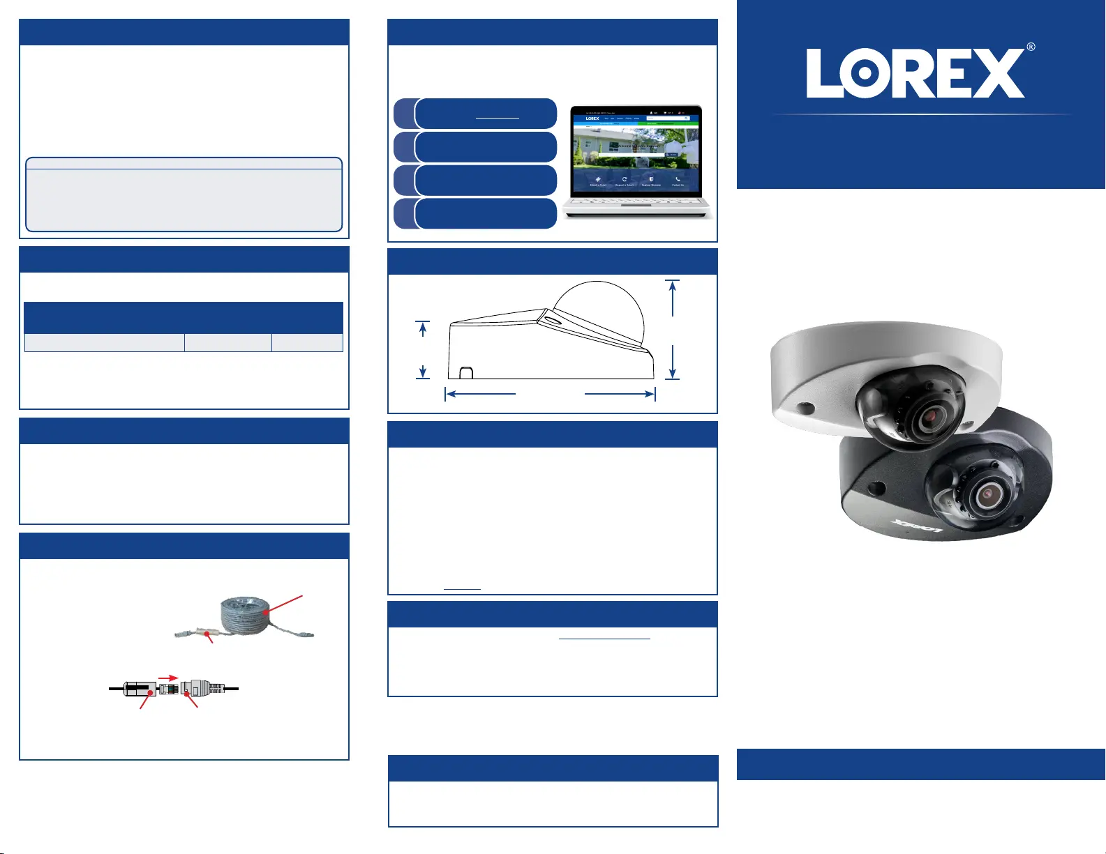
LND4750ABW
| Mærke: | Lorex |
| Kategori: | Overvågningskamera |
| Model: | LND4750ABW |
Har du brug for hjælp?
Hvis du har brug for hjælp til Lorex LND4750ABW stil et spørgsmål nedenfor, og andre brugere vil svare dig
Overvågningskamera Lorex Manualer

3 November 2025
3 November 2025
15 Oktober 2025
11 September 2025
13 August 2025
13 August 2025
12 August 2025
11 August 2025
9 August 2025
9 August 2025
Overvågningskamera Manualer
- Avidsen
- Vosker
- Digitus
- Guxou
- Caliber
- Vtech
- WyreStorm
- Monacor
- Arlo
- Zmodo
- Lindy
- INSTAR
- ION
- Kogan
- Compro
Nyeste Overvågningskamera Manualer

19 December 2025

18 December 2025

18 December 2025

18 December 2025

18 December 2025

18 December 2025

17 December 2025

17 December 2025

17 December 2025

16 December 2025