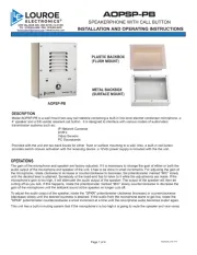
Louroe Electronics AOP-SP-PB Manual


Læs gratis den danske manual til Louroe Electronics AOP-SP-PB (4 sider) i kategorien Intercomsystem. Denne vejledning er vurderet som hjælpsom af 4 personer og har en gennemsnitlig bedømmelse på 3.5 stjerner ud af 2.5 anmeldelser. Har du et spørgsmål om Louroe Electronics AOP-SP-PB, eller vil du spørge andre brugere om produktet?

Side 1/4
DESCRIPTION
AOPSP-PB
PLASTIC BACKBOX
(FLUSH MOUNT)
METAL BACKBOX
(SURFACE MOUNT)
OPERATIONS
Model AOPSP-PB is a wall mount two-way call stations containing a built-in line level electret condenser microphone, a
4” speaker and a 5/8 vandal resistant call button. It is designed to interface with various modes of audio/video
IP Network Cameras
DVR’s
Video Servers
PC Soundcards
Provided with the unit are two back boxes for either flush or surface mounting to a wall. Also, a built-in call button
provides switch closure activation with the receiving device. a 12Vdc power supply is included with the the unit.
The gain of the microphone and speaker are factory adjusted. If it is necessary to change the gain of either or both the
audio output of the microphone and speaker of the unit, it has to be done in small increments. For adjusting the gain of
the microphone, rotate clockwise to increase or counterclockwise to decrease, the potentiometer marked “MIC” slowly
until the desired level is attained. Somebody at the head-end has to listen to it while the adjustments are made. If the
microphone’s gain is too high, it will attenuate the audio output of the speaker. The output of the speaker will then be
cutting off as you talk. If this happens, rotate the potentiometer marked “MIC” slowly counterclockwise to decrease the
gain of the microphone until the talkback sound at the speaker no longer cuts off.
To adjust the audio output of the speaker, rotate the “SPKR” potentiometer clockwise (increase) or counterclockwise
(decrease) slowly until the desired loudness is attained. If the audio from the microphone starts to get low, rotate the
“SPKR” potentiometer counterclockwise a small increment at a time until the microphone audio becomes louder again.
This unit has a built-in muting system that if the microphone’s is too high it is going to mute the speaker and vice versa.
aopsp-pb_inst 3/15
Page 1 of 4
AOPSP-PB
SPEAKERPHONE WITH CALL BUTTON
INSTALLATION AND OPERATING INSTRUCTIONS
6955 VALJEAN AVE, VAN NUYS, CA 91406
PH: (818)994-6498 / FAX: (818)994-6458
/ www.louroe.comtechsupport@louroe.com
®
WIRING CONNECTION TO SPEAKER AND MICROPHONE OF AOPSP-PB
Connect the two wires (black and green) attached to Call Button Switch to the contacts of the
receiving device, using wire nuts and 22 gauge stranded wire. Refer to the receiving device
manufacturers instructions for proper connection.
Page 2 of 4
LOUROE ELECTRONICS® 6 9 5 5 VA L J E A N AVENUE, VAN NUYS, CA 91406 TEL (818) 994-6498 FAX 994-6458
website: www.louroe.com e-mail: sales@louroe.com
(818)
INSTALLATION AND OPERATING INSTRUCTIONS
WIRING CONNECTION TO AOPSP-PB CALL BUTTON
aopsp-pb_inst 3/15
Drill an opening top, bottom or back side
of backbox for passing wiring or for
connecting conduit.
block marked A, B, C, SP
A = 12Vdc power
B = Audio output
C = Ground (bare wire)
SP = Speaker Connection
Bring one end of recommended cable and connect as follows:
Located on the bottom right side of PC board is a 4-pin terminal
1) Connect RED wire to terminal marked “B”
2) Connect BLACK wire to terminal marked “C” (together with bare wire)
3) Connect BARE wire to terminal marked “C“
4) Connect WHITE wire to terminal marked “SP“
5) No connection on terminal “A”
WIRING REQUIREMENTS
3 Conductor consisting of:
+
2 Conductor , 20 gauge shielded
with 22 gauge drain
+
1 Conductor , 20 gauge unshielded
All in the same jacket
WIRING CONNECTION TO IP CAMERA OR DVR
POWER CONNECTION
Bring the other end of the cable to connector that matches the audio input
and outputs of the receiving devices
1) RED (positive audio) and BARE (ground) are soldered to the audio
connector (RCA, 3.5mm Mono or Stereo plugs). This connector goes
to the Audio input of the receiving device (IP Camera, DVR, etc)
2) WHITE (positive audio) and BLACK (ground) are soldered to the another
audio connector (RCA, 3.5mm Mono or Stereo plugs. This connector
goes to the Audio output of the receiving device (IP Camera, DVR,
etc).
The unit has a 2-pin terminal block for power connections marked 12Vdc
1) Connect the positive 12Vdc of the power supply (AD-1) to the terminal
marked +
2) Connect the negative or ground of the power supply to terminal marked
GRD
WIRING CONNECTION TO AOP-SP-PB
See connections on the next page


Produkt Specifikationer

Mærke: Louroe Electronics
Kategori: Intercomsystem
Model: AOP-SP-PB
Bredde: 158.75 mm
Dybde: 69.088 mm
Højde: 203.2 mm
Vægt: 652 g
Produktfarve: Hvid
Husmateriale: Metal
Forbindelsesteknologi: Ledningsført
Højttalertelefon: Ja
Placering: Væg
Nem at installere: Ja
Antal knapper: 1
Frekvens: 0.015 MHz
Indendørsenhed inkluderet: Ingen
Udendørsenhed inkluderet: Ja
IP-tilslutning: Ja

Har du brug for hjælp?

Hvis du har brug for hjælp til Louroe Electronics AOP-SP-PB stil et spørgsmål nedenfor, og andre brugere vil svare dig


Intercomsystem Louroe Electronics Manualer

Intercomsystem Manualer

Nyeste Intercomsystem Manualer