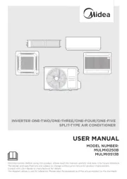
Midea MIH63Q4CHN18 Manual
Midea
Klimaanlæg
MIH63Q4CHN18
Læs nedenfor 📖 manual på dansk for Midea MIH63Q4CHN18 (100 sider) i kategorien Klimaanlæg. Denne guide var nyttig for 11 personer og blev bedømt med 4.9 stjerner i gennemsnit af 6 brugere
Side 1/100

Compact Four-Way
Cassette
Installation and Operation Manual
Read this manual carefully before using the product, and keep it for future reference.
All the pictures in this manual are for illustration purpose only.


Contents
4
68
9
15
Operation
Error Codes / 59
Refrigerant Connecting Piping Installation / 32
Drain Pipe Installation / 38
Installation Materials / 21
Preparations Before Installation / 23
Safety Warning
Safety Precautions / 4 Electric Safety Requirements / 5
1
About The Documentation
About This Document / 1 Safety Instructions / 2
About The Refrigerant / 6
Display Panel / 13
Maintenance And Service
Safety Warning / 68
Cleaning / 68
Service / 71
Operation Precautions / 9Optimum Operation / 10
Symptoms That Are Not Faults / 11
Disposal / 14
Installation
Installation Precautions / 15
Indoor Unit Installation / 25
Electrical Connection / 42
Test Run / 66Settings / 64

About The Documentation
About This Document
Make sure that the user has the printed documentation and ask him/her to keep it for future reference.
Please thoroughly read and ensure that you fully understand the safety precautions (including the signs and
symbols) in this manual, and follow relevant instructions during use to prevent damage to health or property.
NOTE
This appliance is intended to be used by expert or trained users in shops, in light industry, and on farms, or for
commercial and household use by lay persons.
Note
Target audience
Authorised installers + end users
WARNING
Documentation set
This document is part of a documentation set. The complete set consists of:
▪ General safety precautions:
▪ Safety instructions that you must read before installing
▪ Indoor unit installation and operation manual:
▪ Installation and operation instructions
▪ Repeater installation and operation manual:
▪ Installation and operation instructions
▪ Controller installation and operation manual:
▪ Installation and operation instructions
Please refer to the product manual for other accessories.
Technical engineering data
Latest revisions of the supplied documentation may be available via your dealer.
The original documentation is written in English. All other languages are translations.
1

Safety Instructions
NOTE
Useful operation and maintenance information.
Indicates a hazard with a medium level of risk which, if not avoided, could result in
death or serious injury.
Indicates a hazard with a high level of risk which, if not avoided, will result in death or
serious injury.
Indicates a hazard with a low level of risk which, if not avoided, could result in minor
or moderate injury.
WARNING
DANGER
CAUTION
NOTE
Safety Signs
Explanation Of Symbols Displayed On The Unit
The symbols above are for R32 refrigerant system.
WARNING
CAUTION
CAUTION
CAUTION
This symbol shows that the operation manual should be read carefully.
This symbol shows that a service personnel should be handling this equipment with
reference to the installation manual.
This symbol shows that information is available such as the operating manual or
installation manual.
This symbol shows that this appliance used a flammable refrigerant. If the refrigerant
is leaked and exposed to an external ignition source, there is a risk of fire.
Please thoroughly read and ensure that you fully understand the safety precautions (including the signs and symbols) in
this manual, and follow relevant instructions during use to prevent damage to health or property.
WARNING: Risk of fire WARNING: Risk of fire
(for IEC/EN 60335-2-40
except IEC 60335-2-40 2018):
(for IEC 60335-2-40 2018 only):
2

3
DANGER
Any person who is involved with working on or breaking into a refrigerant circuit should hold a current valid
certificate from an industry-accredited assessment authority, which authorises their competence to handle
refrigerants safely in accordance with an industry recognised assessment specification.
Servicing shall only be performed as recommended by the equipment manufacturer. Maintenance and repair
requiring the assistance of other skilled personnel shall be carried out under the supervision of the person
competent in the use of flammable refrigerants.
These instructions are exclusively intended for qualified contractors and authorised installers
• Work on the refrigerant circuit with flammable refrigerant in safety group A2L may only be carried out by
authorised heating contractors. These heating contractors must be trained in accordance with EN 378 Part 4
or IEC 60335-2-40, Section HH. The certificate of competence from an industry accredited body.
• Brazing/soldering work on the refrigerant circuit may only be carried out by contractors certified in
accordance with ISO 13585 and AD 2000, Datasheet HP 100R. And only by contractors qualified and
certified for the processes to be carried out. The work must fall within the range of applications purchased
and be carried out in accordance with the prescribed procedures. Soldering/brazing work on accumulator
connections requires certification of personnel and processes by a notified body according to the Pressure
Equipment Directive (2014/68/EU).
• Work on electrical equipment may only be carried out by a qualified electrician.
• Before initial commissioning, all safety relevant points must be checked by the particular certified heating
contractors. The system must be commissioned by the system installer or a qualified person authorised by
the installer.

DANGER
Safety Warning
OFF
Indoor unit
>2.5m
WARNING CONTENTS
Ensure Proper
Earthing
Professional Only
In the event of refrigerant leakage, smoking and open flames are prohibited. Disconnect
the main power switch immediately, open windows to allow ventilation, keep away from the
leakage point, and contact your local dealer or technical support to request a professional
repair.
Safety Precautions
No Open Flame;
Fire, Open Ignition
Source and Smoking
Prohibited
PROHIBITION SIGNS
No Laying
Inflammable Thing
No Acid or
Alkali Materials
No Strong Currents
4
WARNING
Air conditioner installation must comply with local standards and electrical codes, and
relevant instructions in this manual.
The appliance shall be stored in a well-ventilated area where the room size corresponds to
the room area as specified for operation.
The appliance shall be stored in a room without continuously operating open flames (for
example an operating gas appliance) and ignition sources (for example an operating
electric heater).
The appliance shall be stored so as to prevent mechanical damage from occurring.
Do not use any liquid cleanser, liquefied cleanser, or corrosive cleanser to wipe this unit or
spray water or other liquids on the unit. Otherwise, the plastic parts of the unit will become
damaged and an electrical shock may occur. Disconnect the main power switch before
cleaning and maintenance to avoid accidents.
Ask a professional to remove and reinstall the air conditioner.
Ask a professional for maintenance and repair assistance.
This air conditioner is classified as an "appliance which is not accessible to the general
public".
The indoor unit shall be placed at a height not accessible to children, at least 2.5m above
the ground.

WARNING
Electric Safety Requirements
The air conditioner shall be installed according to the local wiring specifications.
Wiring work must be completed by qualified electricians.
The air conditioner must be well earthed. Specifically, the main switch of the air conditioner
must have a reliable earthing cable.
Before contacting wiring devices, cut off all the power supplies.
The user MAY NOT disassemble or repair the air conditioner. Doing so can be dangerous. In
the event of a fault, immediately cut off the power and contact your local dealer or technical
support.
A separate power supply that meets the rated parameter values must be provided for the air
conditioner.
The fixed wiring to which the air conditioner is connected must be equipped with a power
cut-off device that meets the wiring requirements.
The air conditioner’s circuit board (PCB) is designed with a fuse to provide overcurrent
protection.
The specifications of the fuse are printed on the circuit board.
NOTE: For the units with R32 refrigerant , only the blast-proof ceramic fuse can be used.
5
CAUTION
This appliance is not intended for use by persons (including children) with reduced physical, sensory or
mental capabilities, or lack of experience and knowledge, unless they have been given supervision or
instruction concerning use of the appliance by a person responsible for their safety.
Children should be supervised to ensure that they do not play with the appliance.
The units are partial unit air conditioners, complying with partial unit requirements of this International
Standard, and must only be connected to other units that have been confirmed as complying to corresponding
partial unit requirements of this International Standard.
CAUTION
Under no circumstances should the earth wires of the power supply system be
disconnected.
If the supply cord is damaged, it must be replaced by the manufacturer, its service agent or
similarly qualified persons in order to avoid a hazard.
Do not use a damaged power supply cable and replace it if it is damaged.
When the air conditioner is used for the first time or is in a power-off state for a long time, it
needs to be connected to the power supply and warmed up for at least 12 hours before use.

WARNING
The following applies to R32 refrigerant systems.
Prior to beginning work on systems containing flammable refrigerants, safety checks are necessary to ensure
that the risk of ignition is minimized.
For repair to the refrigerating system, the following precautions shall be complied with prior to conducting work
on the system.
Work shall be undertaken under a controlled procedure so as to minimise the risk of a flammable gas or vapour
being present while the work is being performed.
All maintenance staff and others working in the local area shall be instructed on the nature of work being carried
out. Work in confined spaces shall be avoided. The area around the workspace shall be sectioned off. Ensure
that the conditions within the area have been made safe by control of flammable material.
The area shall be checked with an appropriate refrigerant detector prior to and during work, to ensure the
technician is aware of potentially flammable atmospheres.
Ensure that the leak detection equipment being used is suitable for use with flammable refrigerants, i.e.
non-sparking, adequately sealed or intrinsically safe.
If any hot work is to be conducted on the refrigeration equipment or any associated parts, appropriate fire
extinguishing equipment shall be available to hand. Have a dry powder or CO fire extinguisher adjacent to 2
the charging area.
No person carrying out work in relation to a refrigeration system which involves exposing any pipe work that
contains or has contained flammable refrigerant shall use any sources of ignition in such a manner that it may
lead to the riskof fire or explosion.
All possible ignition sources, including cigarette smoking, should be kept sufficiently far away from the site of
installation, repairing, removing and disposal, during which flammable refrigerant can possibly be released to
the surrounding space.
Prior to work taking place, the area around the equipment is to be surveyed to make sure that there are no
flammable hazards or ignition risks. “No Smoking” signs shall be displayed.
Ensure that the area is in the open or that it is adequately ventilated before breaking into the system or
conducting any hot work. A degree of ventilation shall continue during the period that the work is carried
out. The ventilation should safely disperse any released refrigerant and preferably expel it externally into the
atmosphere.
Where electrical components are being changed, they shall be fit for the purpose and to the correct specification.
At all times the manufacturer’s maintenance and service guidelines shall be followed. If in doubt consult the
manufacturer’s technical department for assistance.
The following checks shall be applied to installations using flammable refrigerants:
– the charge size is in accordance with the room size within which the refrigerant containing parts are installed;
– the ventilation machinery and outlets are operating adequately and are not obstructed;
– if an indirect refrigerating circuit is being used, the secondary circuit shall be checked for the presence of refrigerant;
– marking to the equipment continues to be visible and legible. Markings and signs that are illegible shall be corrected;
– refrigeration pipe or components are installed in a position where they are unlikely to be exposed to any substance
which may corrode refrigerant containing components, unless the components are constructed of materials which are
inherently resistant to being corroded or are suitably protected against being so corroded.
Repair and maintenance to electrical components shall include initial safety checks and component inspection
procedures.
If a fault exists that could compromise safety, then no electrical supply shall be connected to the circuit until it
is satisfactorily dealt with. If the fault cannot be corrected immediately but it is necessary to continue operation,
an adequate temporary solution shall be used. This shall be reported to the owner of the equipment so all parties
are advised.
Initial safety checks shall include:
-that capacitors are discharged: this shall be done in a safe manner to avoid possibility of sparking;
-that no live electrical components and wiring are exposed whiule charging, recovering or purging the system;
-that there is continuity of earth bonding.
About The Refrigerant
6

During repairs to sealed components, all electrical supplies shall be disconnected from the equipment being
worked upon prior to any removal of sealed covers, etc. If it is absolutely necessary to have an electrical supply
to equipment during servicing, then a permanently operating form of leak detection shall be located at the most
critical point to warn of a potentially hazardous situation.
Particular attention shall be paid to the following to ensure that by working on electrical components, the casing
is not altered in such a way that the level of protection is affected. This shall include damage to cables, excessive
number of connections, terminals not made to original specification, damage to seals, incorrect fitting of glands,
etc.
Ensure that seals or sealing materials have not degraded such that they no longer serve the purpose of
preventing the ingress of flammable atmospheres.
Replacement parts shall be in accordance with the manufacturer’s specifications.
Do not apply any permanent inductive or capacitance loads to the circuit without ensuring that this will not
exceed the permissible voltage and current permitted for the equipment in use.
Intrinsically safe components are the only types that can be worked on while live in the presence of a flammable
atmosphere. The test apparatus shall be at the correct rating.
Replace components only with parts specified by the manufacturer. Other parts may result in the ignition of
refrigerant in the atmosphere from a leak.
Check that cabling will not be subject to wear, corrosion, excessive pressure, vibration, sharp edges or any
other adverse environmental effects. The check shall also take into account the effects of ageing or continual
vibration from sources such as compressors or fans.
When breaking into the refrigerant circuit to make repairs – or for any other purpose – conventional procedures
shall be used. However, it is important that best practice is followed.
Since flammability is a consideration. The following procedure shall be adhered to:
• remove refrigerant;
• purge the circuit with inert gas;
• evacuate;
• purge again with inert gas;
• open the circuit by cutting or brazing.
The refrigerant charge shall be recovered into the correct recovery cylinders. The system shall be “flushed” with
OFN to render the unit safe. This process may need to be repeated several times. Compressed air or oxygen shall
not be used for this task.
Flushing shall be achieved by breaking the vacuum in the system with OFN and continuing to fill until the
working pressure is achieved, then venting to atmosphere, and finally pulling down to a vacuum.
This process shall be repeated until no refrigerant is within the system. When the final OFN charge is used, the
system shall be vented down to atmospheric pressure to enable work to take place.
This operation is absolutely vital if brazing operations on the pipe-work are to take place.
Ensure that the outlet for the vacuum pump is not close to any ignition sources and there is ventilation available.
Ensure that contamination of different refrigerants does not occur when using charging equipment. Hoses or
lines shall be as short as possible to minimise the amount of refrigerant contained in them.
Prior to recharging the system it shall be pressure tested with OFN.
DD.12 Decommissioning:
Before carrying out this procedure, it is essential that the technician is completely familiar with the equipment
and all its detail. It is recommended good practice that all refrigerants are recovered safely. Prior to the task
being carried out, an oil and refrigerant sample shall be taken in case analysis is required prior to re-use of
reclaimed refrigerant. It is essential that electrical power is available before the task is commenced.
a) Become familiar with the equipment and its operation.
b) Isolate system electrically.
c) Before attempting the procedure ensure that:
• mechanical handling equipment is available, if required, for handling refrigerant cylinders;
• all personal protective equipment is available and being used correctly;
• the recovery process is supervised at all times by a competent person;
• recovery equipment and cylinders conform to the appropriate standards.
d) Pump down refrigerant system, if possible.
e) If a vacuum is not possible, make a manifold so that refrigerant can be removed from various parts of the system.
f) Make sure that cylinder is situated on the scales before recovery takes place.
g) Start the recovery machine and operate in accordance with manufacturer's instructions.
h) Do not overfill cylinders. (No more than 80 % volume liquid charge).
7

i) Do not exceed the maximum working pressure of the cylinder, even temporarily.
j) When the cylinders have been filled correctly and the process completed, make sure that the cylinders and the
equipment are removed from site promptly and all isolation valves on the equipment are closed off.
k) Recovered refrigerant shall not be charged into another refrigeration system unless it has been cleaned and checked.
Equipment shall be labelled stating that it has been de-commissioned and emptied of refrigerant. The label shall
be dated and signed. Ensure that there are labels on the equipment stating the equipment contains flammable
refrigerant.
When removing refrigerant from a system, either for servicing or decommissioning, it is recommended good
practice that all refrigerants are removed safely.
When transferring refrigerant into cylinders, ensure that only appropriate refrigerant recovery cylinders are
employed. Ensure that the correct number of cylinders for holding the total system charge are available. All
cylinders to be used are designated for the recovered refrigerant and labelled for that refrigerant (i.e. special
cylinders for the recovery of refrigerant). Cylinders shall be complete with pressure relief valve and associated
shut-off valves in good working order. Empty recovery cylinders are evacuated and, if possible, cooled before
recovery occurs.
The recovery equipment shall be in good working order with a set of instructions concerning the equipment
that is at hand and shall be suitable for the recovery of flammable refrigerants. In addition, a set of calibrated
weighing scales shall be available and in good working order. Hoses shall be complete with leak-free disconnect
couplings and in good condition. Before using the recovery machine, check that it is in satisfactory working
order, has been properly maintained and that any associated electrical components are sealed to prevent ignition
in the event of a refrigerant release. Consult manufacturer if in doubt.
The recovered refrigerant shall be returned to the refrigerant supplier in the correct recovery cylinder, and the
relevant Waste Transfer Note arranged. Do not mix refrigerants in recovery units and especially not in cylinders.
If compressors or compressor oils are to be removed, ensure that they have been evacuated to an acceptable
level to make certain that flammable refrigerant does not remain within the lubricant. The evacuation process
shall be carried out prior to returning the compressor to the suppliers. Only electric heating to the compressor
body shall be employed to accelerate this process. When oil is drained from a system, it shall be carried out
safely.
Warning: disconnect the appliance from its power source during service and when replacing parts.
These units are partial unit air conditioners, complying with partial unit requirements of this International
Standard, and must only be connected to other units that have been confirmed as complying to corresponding
partial unit requirements of this International Standard.
8

9
WARNING
Operation
If the unit will be not used for a long time, disconnect the main power switch. Otherwise,
an accident may occur.
The installation height of the air conditioner shall be at least 2.5m above the ground to
avoid the following risks:
1. Touching of moving or live parts, such as fans, motors, or louvers, by a non professional.
Running parts may cause harm to you or transmission assemblies may become damaged.
2.Getting too close to the air conditioner may reduce the level of comfort.
Do not let children play with the air conditioner. Otherwise, an accident may occur.
Do not expose the indoor units or controller to moisture or water as this may cause short
circuiting or fire.
Do not place any appliance that uses an open flame in the direct air supply of the air
conditioner as it could interfere with the combustion of the appliance.
Do not use or store flammable gases or liquids such as natural gas, hair spray, paint or
gasoline near the air conditioner. Otherwise, a fire may occur.
To avoid causing harm, do not place animals or plants directly in front of the air
conditioner's air supply.
In the event of abnormal conditions such as abnormal noise, smell, smoke, temperature
rise, and electric leakage, please cut off the power immediately, and then contact your
local dealer or air conditioner customer service center. Do not repair the air conditioner by
yourself.
Do not place flammable sprayers near the air conditioner or spray it directly at the air
conditioner. Otherwise, a fire may occur.
Do not place a container of water on the air conditioner. If immersed in water, the air
conditioner's electrical insulation will weaken, resulting in electrical shock.
After long-term use, confirm whether the installation platform has become worn. If it is
worn, the unit could fall, causing injury.
Do not operate the switch with wet hands, as this may result in electric shock.
When servicing the air conditioner, be sure to turn off the air conditioner and cut off the
power supply. Otherwise, the high-speed operation of the internal fan will cause injury.
Do not use fuses like iron or copper wire other than those with the specified capacity.
Otherwise, a malfunction or fire may occur. The power supply must use the special circuit
of the air conditioner at the rated voltage.
Do not place valuables under the air conditioner. Air conditioner condensation problems
may damage the valuables.
When the air conditioner needs to be moved and re-installed, please entrust the local
dealer or a professional technician to operate it.
Operation Precautions

10
CAUTION
To use the unit normally, please follow the "Operation" section in this manual. Otherwise,
the internal protection may be triggered, the unit may begin to drip, or the unit's cooling and
heating effects may be impacted.
The room temperature should be set properly, especially when there are elderly, children, or
patients in the room.
Lightning or the starting and stopping of large electrical equipment in nearby factories may
cause misoperation of the air conditioner. Please turn off the main power switch for a few
seconds, and then restart the air conditioner.
To avoid accidental resetting of the thermal circuit breaker, the air conditioner cannot be
powered by an external switching device such as a timer or connected to a circuit that is
turned on and off by a common component timer.
Check whether the air filter is installed properly. Confirm that the inlet and outlet ports of the
indoor unit/outdoor unit are not blocked.
If the air conditioner will not be used for a long time, please clean the air filter before you
start the air conditioner. Otherwise, dust and mold on the filter could contaminate the air or
produce an unpleasant odor. For more details, please refer to the section "Maintenance and
Service".
CAUTION
As cold air sinks and hot air rises, to improve the cooling and heating effects, it is recommended to set the angle of the
lover and ceiling to between 40° to 70° during cooling and heating.
Optimum Operation
Long-term air output at a 40° angle may cause condensation on the surface of the louver. It is recommended to turn on
the anti-condensation function through the wired controller to alleviate this situation.

11
16~32°C
15~30°C
Use the unit in the following temperature and humidity ranges for safe and effective operation.
Operating Range
If it exceeds this operating range, safety devices may be put in action and the unit may not operate.
Cooling Indoor
humidity
Indoor
temperature
Indoor
temperature
Heating
≤80%
(When the humidity exceeds 80%, long-time operation of the indoor unit may cause
dew condensation on the surface of the indoor unit generate mist-like cold air from ,
the air outlet or water dripping out of the unit.)
(Heat
pump type)
Anti-cold air
protection
Protection
Normal Protection Of The Air Conditioner
During operation, the following phenomena are normal and do not require maintenance.
Symptoms That Are Not Faults
In heating mode (including heating in automatic mode), when the indoor heat exchanger does
not reach a certain temperature, the indoor fan temporarily shuts off, or runs in Low mode until
the heat exchanger heats up to prevent the blowing of cold air.
When the power switch is on, the air conditioner starts 3-5 minutes after it is turned ON again
in case it was turned off just before.
(Heat
pump type)
Defrosting
When the outdoor temperature is low and the humidity is high, the outdoor unit’s heat
exchanger may become frosted, which may reduce the heating capacity of the air conditioner.
If this occurs, the air conditioner will stop heating, enter automatic defrosting mode, and return
to heating mode after defrosting has been completed.
During the defrosting, the outdoor fan stops running and the indoor fan runs using the anti-cold
air protection function.
The defrosting operation time varies depending on the outdoor temperature and the degree of
frosting. It generally takes 2 to 10 minutes.
During the defrosting process, the outdoor unit may emit steam due to the rapid defrosting, which is
normal.
When the indoor unit detects high humidity, the air conditioner will adjust the louver angle and
the fan speed to prevent condensation and avoid dripping. (If a third-party panel is selected,
this function is not available.)
Anti-
condensation
NOTE

12
The Following Symptoms Are Not System Malfunctions
①
When humidity is high during cooling mode, white mist may appear due to the humidity and the
temperature difference between the air inlet and outlet.
②
When the air conditioner is switched to heating mode after defrosting, the indoor unit discharges the
moisture generated from defrosting as steam.
The indoor unit emits white mist
When filter is very dirty, dust may enter the indoor unit and be blown out.
The indoor unit blows dust
The indoor unit absorbs the odors of rooms, furniture or cigarettes, etc., and disperses the odors during
operation. It is advised to have the air conditioner cleaned and maintained regularly by professional
technicians.
The indoor unit emits odor
When the indoor humidity is high, condensation and water may drip out of the unit.
Water drips
The following phenomena are normal during operation of the air conditioner. They can be solved
according to the instructions below or do not need to be solved.
During self-cleaning, there may be a slight clicking sound from the melting thin ice about 10
minutes.
"Self-cleaning" sound of icing
① A continuous low "hissing" sound is heard when the system is in "Auto", "Cool", "Dry", and
"Heat" modes. This is the sound of refrigerant gas flowing through both indoor and outdoor
units.
② A "hissing" sound is heard at the start or immediately after stopping operation or defrost
operation. This is the noise of refrigerant caused by flow change.
③ A "zeen" sound is heard immediately after the power supply is turned on. The electronic
expansion valve inside an indoor unit starts working and makes the noise. it will reduce in
about one minute.
④ A continuous low "shah" sound is heard when the system is in cooling mode, dry mode or
at a stop. When the drain pump (optional accessories) is in operation, this noise is heard.
⑤ A "pishi-pishi" squeaking sound is heard when the system stops after heating operation.
Expansion and contraction of plastic parts caused by temperature change make this noise.
⑥ A low "sah", "choro-choro" sound is heard while the indoor unit is stopped. When another
indoor unit is in operation, this noise is heard. In order to prevent oil and refrigerant from
remaining in the system, a small amount of refrigerant is kept flowing.
Noise of Indoor unit
When the indoor unit reaches the set temperature, the air conditioner controller automatically
stops the compressor operation and switches to the fan only mode. When the room temperature
rises (in cooling mode) or falls (in heating mode) to a certain level, the compressor is restarted
and cooling or heating operation is resumed.
Switching from cooling/heating (not available for cooling only units) mode to fan only mode

13
① In heating mode, the air-conditioning system absorbs heat from the outdoor air and
releases heat to the indoor side. When the outdoor temperature is low, less heat is
released. This is the principle of heat pump.
② When the outdoor temperature is extremely low, the heating capacity of the air conditioner
decreases, and other heating equipment may need to be added.
In winter, the outdoor temperature is low, and heating effects may be decreased
For the same air conditioning system, if outdoor unit operates in changeover mode, the wired
controller of VIP indoor unit allows users to select modes supported by the indoor units, while the
wired controllers of other indoor units displays the icon of " ". In this case,
other indoor units can only operate in the same mode as the VIP indoor unit.
No heating or cooling permissions
No permission
Display Panel
NOTE
Humidity* : The humidity control functions is customized.
Some display functions are available only for certain indoor unit and outdoor unit models, wired controllers,
and display panels. For more information, please consult your local dealer or technical support.
Display functions:
① In Standby mode, the main interface displays “---”.
② When starting up in Cooling or Heating mode, the main interface displays the set temperature. In Fan
mode, the main interface displays the indoor temperature. In Dry mode, the main interface displays the set
temperature, and when the humidity* is set, the set humidity value is displayed on the wired controller.
③ The light display on the main interface can be turned on or off through the light button on the remote
controller.
④ When the system fails or runs in a special mode, the main interface displays the error code or the operating
status codes. For details, see the section “Error Codes and definitions”.

14
Disposal
Components and accessories from the units are not part of ordinary domestic waste.
Complete units , compressors, motors etc. are only to be disposed of via qualified disposal specialists.
This unit uses hydrofluorocarbon which is only be disposed of via qualified disposal specialists.

15
Installation
Carefully read this manual before installing the indoor unit.
Installation Precautions
WARNING
Make sure to carry out the installation according to local legislation.
Ask your local dealer or professionals to install the product.
This unit must be installed by pqualified persons. Users MAY NOT install the unit themselves;
otherwise, faulty operations may cause the risks of fire, electrical shock, injury, or leakage, which
could harm you or others or damage the air conditioner.
Never modify or repair the unit on your own.
Otherwise, a fire, electric shock, injury or water leakage may occur. Get your local dealer or a
professional to do so.
Make sure that the residual current device is installed.
The residual current device must be installed. Failure to install it may result in electric shock.
When powering the unit, follow the regulations of the local electric companies.
Make sure that the unit is earthed reliably in accordance with laws. If the earthing is not completed
correctly, it may cause electrical shock.
When moving, disassembling or reinstalling the air conditioner, get the assistance of your
local dealer or a professional.
If installed improperly, fire, electrical shock, injury, or water leakage may occur.
Use the optional accessories specified by local dealer.
The installation of these accessories must be carried out by professionals. Improper installation
may cause fire, electrical shock, water leakage and other hazards.
Use only power supply cable and communication cables that meet specification
requirements. Properly connect all the wiring to make sure that no external forces are
acting on the terminal blocks, power supply cable and communication cables. Improper
wiring or installation may cause a fire.
The air conditioner must be earthed. Check whether the earth line is securely connected or
broken. Do not connect the earth line to gas cans, water piping, lightning rods or telephone
earth lines.
The main power switch of the air conditioner should be put in a position that is out of the
reach of children.
It should not be obstructed by flammable objects such as curtains.
Open flames are prohibited when refrigerant leaks are present.
If the air conditioner is not cooling/heating properly, this may be caused by a refrigerant leak. If this
occurs, contact your local dealer or a professional. The refrigerant in the air conditioner is safe, and
usually does not leak.
If there is refrigerant leakage in the room, it is easy for a fire to occur after contact with the heating
units of the heater/electric stove/stove. Please disconnect the power supply of the air conditioner,
extinguish the flames of appliances that produce a flame, and open the windows and doors of the
room to allow ventilation and ensure that the concentration of refrigerant leakage in the room does
not exceed a critical level; keep away from the leakage point, and contact the dealer or professional
personnel.
After the refrigerant leakage is repaired, do not start the product until the maintenance
personnel confirms that the leakage is well repaired.

16
CAUTION
indoo r unit
GAS
Before and after installation, exposing the unit to water or moisture will cause electrical
short circuit.
Do not store the unit in a humid basement or expose it to rain or water.
Make sure the installation base and lifting are robust and reliable;
Insecure installation of the base may cause the air conditioner to fall, leading to an accident. Take
into full consideration the effects of strong winds, typhoons and earthquakes, and reinforce the
installation.
Check whether the drain pipe can drain the water smoothly.
Improper installation of the pipeline may lead to water leakage, damaging furniture, electric
appliances, and the carpet.
After installation, check whether the refrigerant is leaking.
Do not install the product in a location where there is a danger of flammable gas leaks.
In the event of leakage of combustible gas, the combustible gas surrounding the indoor unit may
cause a fire.
Keep the indoor unit, outdoor unit, power supply cable, and connecting wires at least 1m away from the
high-power radio equipment, to prevent electromagnetic interference and noise. For some electromagnetic
waves, it is not enough to prevent noise even at a distance of more than 1m.
In a room equipped with fluorescent lamps (rectifier type or fast start type), the signal transmission distance
of the remote controller (wireless) may not reach the predetermined value. Install the indoor unit as far away
from the fluorescent lamp as possible.
Do not touch the fins of the heat exchanger, as this could cause injury.
For safety, please dispose of the packing materials properly.
Nails and other packaging materials may cause personal injury or other risks. Tear up the plastic packaging bag and
dispose of it properly to prevent children from playing with it, leading to suffocation.
Do not cut off the power supply immediately after the indoor unit stops running.
Some parts of the indoor unit like the valve body and water pump are still in operation. Please wait for at least 5 minutes
before cutting off the power supply. Otherwise, water leakage and other faults may occur.
If the temperature and humidity in the ceiling mezzanine may exceed 30 RH80%, please put insulation ℃
material on the unit.
Please use glass wool or foamed polyethylene as insulation material, the thickness of which is required to be 10mm or
more, and can be stored in the ceiling opening.
For evaporating units and condensing units, the instructions or markings shall include a wording to assure
that the maximum operating pressure is considered when connecting to any condenser unit or evaporator unit.
For evaporating units, condensing units and condenser units, the instructions or markings shall include
refrigerant charging instructions.
A warning to assure that partial units shall only be connected to an appliance suitable for the same refrigerant.
This unit is a partial unit air conditioner, complying with partial unit requirements of this International
Standard, and must only be connected to other units that have been confirmed as complying to corresponding
partial unit requirements of this International Standard.
The electrical interfaces shall be specified with purpose, voltage, current, and safety class of construction.
The SELV connection points, if provided, are to be clearly indicated in the instructions.
The connection point should be marked with the “read the instructions” symbol per ISO 7000-0790 (2004-01)
and the Class III symbol according to IEC 60417-5180 (2003-02).
For R32 Refrigerant only.
This unit is equipped with a refrigerant leak detector for safety. To be effective, the unit must be electrically powered at
all times after installation, other than when servicing.
If any supplemental unit is employed to detect leaked refrigerant, such unit shall also apply this marking or be
accompanied by such instructions.

1717
WARNING
CAUTION
3
2
4
1
Do not unpack the air conditioner until it is transported to the installation site.
When unpacking and moving the air conditioner, must hold the and do not apply force Lifting Lugs
to other parts, especially the refrigerant piping, drain pipe and plastic accessories, so as to avoid
damaging the air conditioner and causing personal injury.
Before installing the air conditioner, make sure that the refrigerant specified on the nameplate is being
used.
Forbidden Installation Sites
A place filled with mineral oil, fumes or mist, like a kitchen.
Plastic parts will age and the heat exchanger will become dirty, eventually causing the air
conditioner performance to deteriorate or leak water.
Connecting pipes and copper welds will be corroded, resulting in refrigerant leakage.
A place where there are corrosive gases, such as acid or alkaline gases.
Connecting pipes and copper welds will be corroded, resulting in refrigerant leakage.
A place exposed to combustible gases and using volatile combustible gases such as diluent or
gasoline.
The electronics in the air conditioner may cause the surrounding gas to ignite.
A place where there is equipment emitting electromagnetic radiation.
The control system will fail and the air conditioner will not function properly.
A place where there is a high salt content in the air like a coastal area.
Do not use the air conditioner in an environment where an explosion may occur.
The unit cannot be installed on moving vehicles such as truck and ship.
Factories with major voltage fluctuations in the power supplies.
Other special environmental conditions.
Precautions For Transporting And Lifting The Air Conditioner
Before transporting the air conditioner, determine the path that will be used to move it to the installation
site.
Air conditioner units of this series are designed to provide comfort. Don’t install the unit in mechanical rooms and rooms
with precision instruments, food, plants, animals, or artwork.
Avoid installation in an environment with a lot of organic compounds such as ink and siloxane.
The total refrigerant charge in the system cannot exceed the requirements for minimum room size of the smallest one
that is served.
Do not install or use the air conditioner in the following places:
NOTE
Wooden buildings, newly renovated houses, and frequent use of disinfectants may contain acidic components in the
air, such as formic acid , acetic acid, and hypochlorous acid, which can corrode copper pipes and solder joints, leading
to refrigerant leaks.
Factories, chemical plants, livestock farms, vegetable markets, sewage pits, and other environment may contain
sulfides, acid gases such as sulfur dioxide, ammonia, and chlorides in the air, which can corrode copper pipes and
solder joints, leading to refrigerant leaks.
Please contact a dealer for assistance.

18
Keep the air-conditioning return air away from direct exposure to the sun in the room.
The indoor unit should not be lifted in the places like load-bearing beams and columns that affect the structural safety of the
house.
The wired controller and the indoor unit should be in the same installation space; otherwise, the sampling point
setting of the wired controller needs to be changed.
Choose a site that fully complies with the following conditions and user requirements to install the
air conditioning unit:
There is enough space for installation and maintenance.
The ceiling is level, and the structure is strong enough to
support the indoor unit. If necessary, take measures to
reinforce the unit's stability.
Airflow in/out of the machine is not obstructed, and the
external air exerts minimum impact.
It is easy to supply airflow to every corner of the room.
It is easy to drain fluids from the connected piping and water
drain piping.
There is no direct heat radiation.
Avoid installation in narrow spaces or where there are more
stringent noise requirements.
The indoor unit needs to be installed at a position greater than
2.5m and less than 3.5m from the ground.
Condensate water can be discharged smoothly.
The length of the piping between the indoor and outdoor units
is within the permitted range. Refer to the Installation and
Operation Manual attached with the outdoor unit.
≥250
Ceiling
Air inlet
Air outlet Air outlet
Panel
Floor
590x590 (ceiling opening dimension)
>2500
(Unit: mm)
>1000 >1000
>
1000
>1000
Air outlet
Louver Air outlet
Display
panel
Return
air inlet
(Unit: mm)

19
NOTE
Panels, wired controllers, and remote controllers are available in various models. All the optional
accessories should be from local dealer.
For optional accessories such as wired controllers, please refer to the manuals of these accessories.
All the figures in the manual explain only the general appearance and functions of the product. The
appearance and functions of the purchased product may not be completely consistent with those listed in the
figures. Please refer to the actual product.
Layout
Installation layout
8
4
13
6 5715 3 2 1
10
11
9
12
14
16
14
*Power cable and earth wires
13
Access hole
16
North American inlet hole (two)
* To be purchased separately on site.
15
*Communication wiring
10
Wired controller (optional)
12
Electric control box
11
Remote controller (optional)
6
Liquid pipe
8
Drain pipes
7
Gas pipe
9
*Connection wires
5
Fresh air inlet
2
Panel (optional)
1
Indoor unit
4
Expanded outlet
3
Air outlet

20
Product Dimensions
(Unit: mm)
A: Connect to refrigerant piping (liquid side) B: Connect to refrigerant piping (gas side)
Φ6.35
Φ9.52
Φ12.7
Φ15.9
Φ22.2
620 (with panel)
530
575
575
620 (with panel)
530 235
120
575
638
26
6-M4
27.5
250
27.5
250
420
Φ170
95
6-M4
Φ125
26
48
Φ22.2
Φ170
6-M4
140
235
Φ100
Φ150
Φ150
17
12
12
32
B
A
Φ23 (internal diameter)
Drain pipe Φ25
(outer diameter)
kW≤5.6
5.6<kW≤6.3
364
Capacity (kW)
120

21
NOTE
(a) (b) (c)
Check the accessory kit for the above items and contact your local dealer for any missing items.
Do not throw away any accessories that may be required for installation until the installation is complete.
Customers are free to choose to buy wired controllers, remote controllers (with a seven-speed wind
controller) and other optional accessories.
Except primary efficiency filters, medium efficiency filters are optional.
When installing the insulation pipe on site, please cut it according to the actual needs. (Either method (a) or (b)
is OK. Method (c) is incorrect. There must be no gap between the insulation pipe and connecting pipe.)
Clearance
Not connected
Installation Materials
Accessories
Installation And Operation
Manual X 1
(Make sure to hand it over to the
user)
Thermal Insulation Pipe X 2
Used for insulation and
anti-condensation at pipe
connections.
Flare Nut X 2
For use in the installation of
connecting pipe (the quantity is
one for models with a process
pipe)
To tighten the drain hose tightly to
the drainage outlet and PVC
piping of the indoor unit.
Cable Tie X 4
List of accessories
Primary filter Medium efficiency filter
Copper Pipe
Used to connect the indoor
refrigerant piping.
Thermal Insulation Pipe
Used to prevent pipe
condensation.
PVC Water Drain Pipe
Used to drain the
condensed water from the
indoor unit.
Used to install the indoor
unit.
Expansion Bolt (M10)x4
Used to install the indoor
unit.
Suspension Bolt (M10)x4
List of accessories
Locally Purchased Accessories
Produkt Specifikationer
Mærke: | Midea |
Kategori: | Klimaanlæg |
Model: | MIH63Q4CHN18 |
Har du brug for hjælp?
Hvis du har brug for hjælp til Midea MIH63Q4CHN18 stil et spørgsmål nedenfor, og andre brugere vil svare dig
Klimaanlæg Midea Manualer

18 Februar 2025

18 Februar 2025

17 Februar 2025

12 Februar 2025

12 Februar 2025

12 Februar 2025

11 Februar 2025

24 December 2024

5 December 2024

5 December 2024
Klimaanlæg Manualer
- Klimaanlæg Termozeta
- Klimaanlæg Elba
- Klimaanlæg Camry
- Klimaanlæg SereneLife
- Klimaanlæg Everglades
- Klimaanlæg Tatung
- Klimaanlæg Alberello
- Klimaanlæg Altech
- Klimaanlæg Mitsubishi
- Klimaanlæg Maiko
- Klimaanlæg Dantherm
- Klimaanlæg VOX
- Klimaanlæg Suntec
- Klimaanlæg Mobile Airco
- Klimaanlæg TecLime
Nyeste Klimaanlæg Manualer

10 April 2025

10 April 2025

10 April 2025

10 April 2025

10 April 2025

10 April 2025

10 April 2025

10 April 2025

10 April 2025

10 April 2025