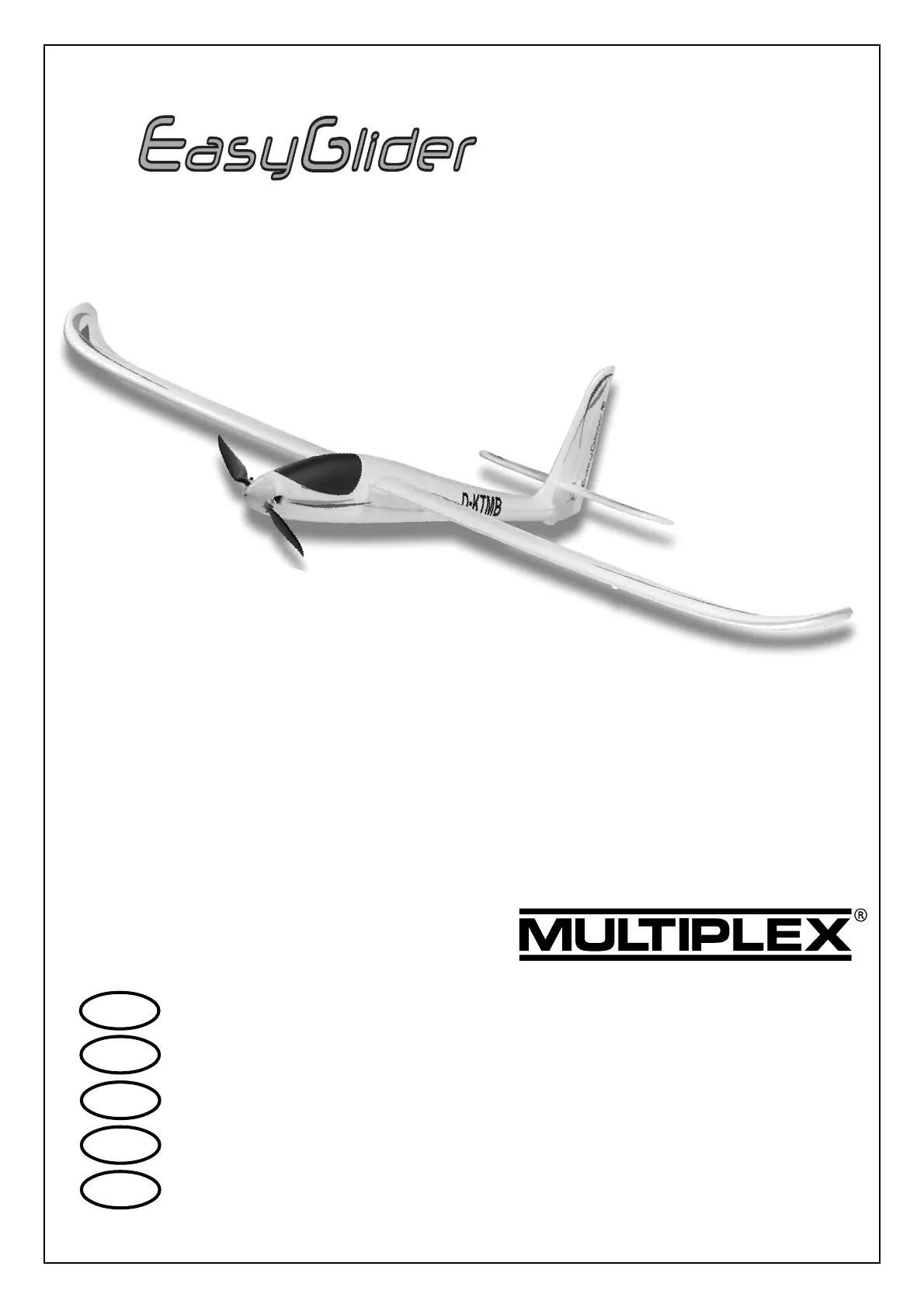
Multiplex Kit EasyGlider PRO Manual
Multiplex
Radiostyret legetøj
Kit EasyGlider PRO
Læs nedenfor 📖 manual på dansk for Multiplex Kit EasyGlider PRO (52 sider) i kategorien Radiostyret legetøj. Denne guide var nyttig for 35 personer og blev bedømt med 4.5 stjerner i gennemsnit af 2 brugere
Side 1/52

1
GB
D
E
I
Bauanleitung 03 ... 10
Building instructions 11 ... 19
Notice de construction 20 ... 33
Istruzioni di montaggio 34 ... 41
Instrucciones de montaje 42 ... 49
© Copyright by MULTIPLEX 2008Version 1.0
BK / KIT EasyGlider PRO # 21 4226
F
PRO
vorgesehen für die MULTIPLEX
Brushless-Antriebe # 33 2636 u. # 33 2642
oder als Segler

2
D
F
GB
I
E
Sicherheitshinweise
Prüfen Sie vor jedem Start den festen Sitz des Motors und der Luftschraube - insbesondere nach dem Transport, härteren Landungen
sowie Abstürzen. Prüfen Sie ebenfalls vor jedem Start den festen Sitz und die richtige Position der Tragflächen auf dem Rumpf.
Akku erst einstecken, wenn Ihr Sender eingeschaltet ist und Sie sicher sind, daß das Bedienelement für die Motorsteuerung auf "AUS"
steht.
Im startbereiten Zustand nicht in den Bereich der Luftschraube greifen.
Vorsicht in der Luftschraubendrehebene - auch Zuschauer zur Seite bitten!
Zwischen den Flügen die Motortemperatur durch vorsichtige Fingerprobe prüfen und
vor einem Neustart den Motor ausreichend abkühlen lassen. Die Temperatur ist richtig, wenn Sie den Motor problemlos berühren
können. Insbesondere bei hohen Außentemperaturen kann dieses bis zu 15 Minuten dauern.
Denken Sie immer daran: Niemals auf Personen und Tiere zufliegen.
Conseils de sécurité
Avant chaque décollage, vérifiez la fixation du moteur et de l'hélice, notamment après le transport, après les atterrissages violents et
après un “Crash”. Vérifiez également, avant chaque décollage la fixation ainsi que le positionnement de l’aile par rapport au fuselage.
Ne branchez l’accu de propulsion que si vous êtes sûr que votre émetteur est allumé et que l’élément de commande moteur est en
position “ARRET”.
Ne mettez pas vos doigts dans l’hélice! Attention à la mise en marche, demandez également aux spectateurs de reculer.
Entre deux vols, vérifiez en posant un doigt dessus, la température du moteur, laissezle refroidir suffisamment avant le prochain
décollage. La température est correcte si vous pouvez maintenir votre doigt ou votre main sur le moteur. Le temps de refroidissement
peut varier jusqu’à 15 minutes s’il fait particulièrement chaud.
Pensez-y toujours: ne volez jamais vers ou au-dessus des personnes ou des animaux.
Safety notes
Before every flight check that the motor and propeller are in place and secure - especially after transporting the model, and after hard
landings and crashes. Check also that the wing is correctly located and firmly secured on the fuselage before each flight.
Don’t plug in the battery until you have switched on the transmitter, and you are sure that the motor control on the transmitter is set to
“OFF”.
When the model is switched on, ready to fly, take care not to touch the propeller. Keep well clear of the propeller disc too, and ask
spectators to stay back.
Allow the motor to cool down after each flight. You can check this by carefully touching the motor case with your finger. The
temperature is correct when you can hold your finger on the case without any problem. On hot days this may take up to 15 minutes.
Please keep in mind at all times: don’t fly towards people or animals.
Note di sicurezza
Prima di ogni decollo controllare che il motore e la eliche siano fissati stabilmente - specialmente dopo il trasporto, atterraggi duri e se il
modello è precipitato. Controllare prima del decollo anche il fissaggio e la posizione corretta delle ali sulla fusoliera.
Collegare la batteria solo quando la radio è inserita ed il comando del motore è sicuramente in posizione ”SPENTO”.
Prima del decollo non avvicinarsi al campo di rotazione della eliche. Attenzione alla eliche in movimento - pregare che eventuali spettatori
si portino alla dovuta distanza di sicurezza!
Tra un volo e l’altro controllare cautamente con le dita la temperatura del motore e farli raffreddare sufficientemente prima di ogni nuovo
decollo. La temperatura è giusta se si possono toccare senza problemi. Specialmente con una temperatura esterna alta questo può
durare fino a 15 minuti.
Fare attenzione: Non volare mai nella direzione di persone ed animali.
Advertencias de seguridad
Compruebe antes de cada despegue que el motor y la hélice estén fuertemente sujetados, sobretodo después de haberlo transportado,
de aterrizajes más fuertes así como después de una caída. Compruebe igualmente antes de cada despegue que las alas estén bien
sujetas y bien colocadas en el fuselaje.
Conectar la batería, cuando la emisora esté encendida y Usted esté seguro que el elemento de mando para el motor esté en ”OFF”.
No meter la mano en la zona inmediata a la hélice cuando el avión esté a punto de despegar. ¡Cuidado con la zona de la hélice! ¡Pedir a
los espectadores que se aparten!
Entre los vuelos hay que comprobar cuidadosamente la temperatura del motor con el dedo y dejar que el motor se enfríe antes de volver
a despegar. La temperatura es correcta, si puede tocar el motor sin problemas. Sobretodo en el caso de temperaturas del ambiente muy
altas, esto puede tardar unos 15 minutos.
Recuerde: No volar nunca hacía personas o animales.

4
Wichtiger Hinweis
Dieses Modell ist nicht aus Styropor ™! Daher sind Verklebungen mit Weißleim oder Epoxy nicht möglich. Verwenden Sie
nur Cyanacrylatkleber (Sekundenkleber), vorzugsweise in Verbindung mit Aktivator (Kicker). Für alle Verklebungen ver-
wenden Sie Cyanacrylatkleber in mittlerer Viskosität. Sprühen Sie bei Elapor® immer eine Seite mit Aktivator (Kicker) ein
– lassen diesen 2 Minuten ablüften und geben Sie auf die andere Seite den Cyanacrylatkleber an. Fügen Sie die Teile
zusammen und positionieren Sie diese sofort.
Vorsicht beim Arbeiten mit Cyanacrylatklebern. Diese Kleber härten in Sekunden, daher nicht mit den Fingern und
anderen Körperteilen in Verbindung bringen. Zum Schutz der Augen unbedingt Schutzbrille tragen!
Von Kindern fernhalten!
5. Hochstarthaken einbauen
Beim Segelflugmodell wird nun der Hochstarthaken 32 in das
Formnest der Rumpfhälfte 4 geklebt.
Abb. 9
6. Einbau des Motorträgers
Den Motorträger 34 in die rechte Rumpfhälfte einkleben. Es soll
kein Kleber austreten und die später beim Zusammenbau zu
verklebende Motorträgerhälfte soll jetzt noch frei von Klebstoff
bleiben. Der Motorträger wird auch beim Segler aus Festigkeits-
gründen eingebaut.
Abb. 10
7. Servos in die Rumpfhälften einbauen
Stellen Sie die Servos mit der Fernsteuerung auf „Neutral“ .
Die Servos wie in Abb. 11 gezeigt seitlich in die linke und rechte
Rumpfhälfte stecken. Bei Verwendung von anderen Servos, kön-
nen kleinere Anpassarbeiten notwendig werden.
Die Servokabel von unten nach oben in die Aussparung legen
und mit Klebeband fixieren. Die Servos mit einem Tropfen CA-
Kleber an den Laschen im Schaum befestigen. Nun die Z-
Drähte in die Servohebel einstecken und diese im Winkel von
90° auf dem Servo montieren (Schraube nicht vergessen. Die
Verschlussklammern 22 rechts und links im Rumpf einkleben.
In die Kabelhalter 36 die Verlängerungskabel bündig einkle-
ben. Die Kabelhalter 36 rechts und links in die Formnester bis
zum Anschlag in die Rumpfhälften kleben. Die Kabel verlegen
und die Rumpflängsspanten 37 einkleben.
Abb.11
8. Zusammenkleben der Rumpfhälften
Der geeignete Kleber für diese Verbindung ist CA Kleber dick-
flüssig (Sekundenkleber) in Verbindung mit Aktivator.
Achtung: Bei der Tuning-Version (bei Motoren von ca. 135g)
werden zuvor noch die 2 Ausgleichsgewichte 33 wie in Abb.
12 gezeigt eingeklebt.
Die Rumpfhälften 3 + 4 werden zunächst noch ohne Klebstoff
geprüft, ob sich diese einwandfrei zusammenfügen lassen –
ggf. an entsprechender Stelle nacharbeiten.
Rumpfhälfte 4 mit Aktivator einsprühen und 2min. ablüften las-
sen.
Rumpfhälfte 3 an den Verbindungsstellen und auch am Motor-
träger mit Klebstoff versehen und mit 4 sorgfältig zusammen-
fügen und ausrichten! Die Rumpfnaht muss gerade verlaufen
und darf nicht gebogen sein!
Abb. 12
9. Seitenruderscharnier einbauen
Das Scharnier 31 mit wenig Sekundenkleber im Rumpfende
einkleben. Achten Sie insbesondere darauf, dass kein Kleber
in das Scharnier kommt.
Abb. 13
An der Vorderkante des Seitenruders mittig mit einem Klingen-
1. Vor dem Bau
Prüfen Sie den Inhalt Ihres Baukastens.
Dazu sind die Abb. 1+2 und die Stückliste hilfreich.
Fertigstellung des Rumpfes und der Leitwerke
2. Vorbereitung der Bowdenzüge
Die Länge der Höhenruder-Bowdenzugrohre 43 und 45
kontrollieren und ggf. kürzen.
43 Ø 3/2 x 785 mm
45 Ø 2/1 x 850 mm
Stahl 41 Ø 0,8 x 875 mm einstecken!
Ebenso mit den Seitenruder-Bowdenzugrohren 44 und 46
verfahren.
44 Ø 3/2 x 785 mm
46 Ø 2/1 x 850 mm
Stahl 42 Ø 0,8 x 875 mm einstecken!
Antennenrohr 47 Ø 3/2 x 785 mm (ggf. kürzen)
3. Einbau der Bowdenzüge in die Rumpfhälften
Achtung: Durch die sorgfältige Verklebung der Bowdenzug-
aussenrohre 43 44 und sowie dem Antennenrohr 47 auf der
gesamten Länge mit dem Rumpf entsteht ein erheblicher
Stabilitätszuwachs am Leitwerksträger.
Achten Sie auch auf die Leichtgängigkeit der Bowdenzüge und
dass kein Klebstoff in das Bowdenzugrohr gelangt.
Linke Rumpfhälfte:
Den kompletten Höhenruder-Bowdenzug (Stahldrahtlänge =
875mm) in die linke Rumpfhälfte stecken. Die Z-Biegung zeigt
zum Servo.
Abb. 3
Bowdenzugaussenrohr 43 vorne in der Rumpfhälfte nach Abb.
4 bündig positionieren. Rumpfhälfte flach auflegen und mit
Sekundenkleber das Aussenrohr 43 auf der gesamten Nut-
länge der Rumpfhälfte festkleben.
Abb. 5
Rechte Rumpfhälfte:
Den kompletten Seitenruder-Bowdenzug (Stahldrahtlänge =
875mm) Die Z-Biegung zeigt Richtung Servo.
Abb. 6
Bowdenzugaussenrohr 44 vorne in der Rumpfhälfte nach Abb.
7 bündig positionieren. Rumpfhälfte flach auflegen (achten Sie
auf die Arretierzapfen / Rumpfhälfte über Eck flach auf den Tisch
legen) und mit Sekundenkleber das Aussenrohr 44 auf der
gesamten Aussennut der Rumpfhälfte festkleben.
Abb. 8
4. Antennenrohr einbauen
Antennenrohr 47 anpassen, ablängen und in die rechte
Rumpfhälfte kleben - Rumpf dabei nicht verbiegen! Abb. 9

5
messer den Ausschnitt für das Ruderscharnier 31 ausschnei-
den. Bitte Vorsicht! Verletzungsgefahr. Den Schlitz im Ruder 5
nach unten ca. 3 bis 4mm länger schneiden, damit Seiten- und
Höhenruder später bequem auf dem Rumpf montiert werden
können.
10. Ruderhorn am Seitenruder befestigen
Das T-Stück des Ruderhorns 24 für das Seitenruder 13 auf ca.
2mm kürzen (Seitenschneider). Gestängeanschluss 25 in die
zweite Bohrung von innen in das Ruderhorn 24 stecken und
mit der U-Scheibe 26 und der Mutter 27 befestigen. Achtung:
Beachten Sie die Einbaurichtung! Die Mutter vorsichtig so anzie-
hen, dass der Gestängeanschluss nicht wackelt und nicht
klemmt. Anschliessend mit einem Abstrich (Nadel) Sekunden-
kleber sichern. Den Inbusgewindestift 28 mit dem Inbusschlüs-
sel 29 im Gestängeanschluss 25 vormontieren.
Das Ruderhorn 24 - mit der Lochreihe zur Scharnierlinie zeigen.
In das zuvor mit Aktivator benetzte Nest des Seitenruders einkle-
ben.
Abb. 14
11. Höhen- und Seitenruder gängig machen
Am Höhenleitwerk 12 das Höhenruder seitlich frei schneiden
(1 mm Schlitz). Die Scharnierkanten von Seiten- und Höhenru-
der durch hin- und herbewegen „gängig“ machen - keinesfalls
das Ruder abtrennen!
Abb. 16
12. Ruderhorn am Höhenruder befestigen
Gestängeanschluss 25 in äusserste Bohrung in das Ruder-
horn 24 26 stecken und mit der U-Scheibe und der Mutter 27
befestigen. Achtung: Beachten Sie die Einbaurichtung! Die
Mutter mit Gefühl anziehen und anschliessend mit einem Ab-
strich (Nadel) Sekundenkleber sichern. Den Inbusgewindestift
28 mit dem Inbusschlüssel 29 25 im Gestängeanschluss vor-
montieren.
Das Ruderhorn 24 - mit der Lochreihe zur Scharnierlinie zei-
gend - in das zuvor mit Aktivator benetzte Nest des Höhenru-
ders einkleben.
Abb. 17
13. Höhen- und Seitenleitwerk verkleben
Höhenleitwerk 12 und das Seitenleitwerk 13 im 90° Winkel mit-
einander verkleben. Verwenden Sie zur Überprüfung z.B. ein
Geo-Dreieck.
Abb. 18
14. Leitwerke mit dem Rumpf verkleben
Das Höhen- und Seitenleitwerk probehalber noch ohne Kleb-
stoff auf dem Rumpf positionieren und die Passgenauigkeit
überprüfen. Dabei zuerst das Scharnier 31 im Seitenruder 13
ansetzen und die Leitwerke anschliessend nach vorne in Po-
sition bringen. Achten Sie hier besonders darauf, dass das
Höhenleitwerk 12 spaltfrei auf dem Rumpf aufliegt und parallel
zur Tragflächenauflage - vorne im Rumpf - ist. Der Holmverbin-
der 40 wird hierzu als Hilfsmittel quer im Tragflächenausschnitt
positioniert (z.B. mit Kreppband sichern). Nun von der Rumpf-
nase her über den Holmverbinder peilen und so das Höhen-
leitwerk ausrichten. Wenn sich die Leitwerke so ausrichten las-
sen werden diese mit dem Rumpf verklebt. Ausrichtung und
Spaltfreiheit nochmals überprüfen! Wenn Sie hier nicht genau
arbeiten, werden Sie sich ein Modellflugzeugleben lang dar-
über ärgern.
15. Höhen- und Seitenrudergestänge arretieren
Die Stahldrahtenden 41 42 und durch die Gestängeanschlüsse
25 führen - Servos und Ruder auf Neutral stellen und mit den
Inbus-Gewindestiften 28 festklemmen.
Abb. 19 + 20
Fertigstellung der Tragflächen
16. Querruder gängig machen
An den Tragflächen 8 und 9 die Querruder seitlich freischneiden
(1 mm Spalt). Die Scharnierkanten durch hin- und herbewegen
„gängig“ machen - keinesfalls die Ruder abtrennen!
Abb. 21
17. Ruderhörner am Querruder befestigen
In die beiden Ruderhörner für die Querruder die Gestängean-
schlüsse 25 in die äusserste Bohrung der Ruderhörner 24
stecken. Mit den U-Scheiben 26 und den Muttern 27 befesti-
gen.
Achtung: 1x links und 1x rechts! Die Muttern mit Gefühl anzie-
hen und anschliessend mit einem Abstrich (Nadel) Sekunden-
kleber sichern. Den Inbusgewindestift 28 mit dem Inbusschlüs-
sel 29 im Gestängeanschluss 25 vormontieren.
Die Ruderhörner 24 - mit der Lochreihe zur Scharnierlinie zei-
gend - in das zuvor mit Aktivator benetzte Nest der Querruder
einkleben.
Abb. 22
18. Querruderservos montieren
Stellen Sie die Servos mit der Fernsteuerung auf „Neutral“. Mon-
tieren Sie die Servohebel so auf den Servos, dass die Hebel in
Neutralstellung 90° seitlich überstehen - 1x links und 1x rechts
(also gespiegelt).
Die Servos in die Formnester der Tragflächen 8 und 9
einpassen. Dem verwendeten Servotyp entsprechend, können
kleinere Anpassarbeiten notwendig werden. Zum Einkleben
jeweils einen Tropfen Heisskleber in die Schlitze für die
Servolaschen am Flügel angeben und das Servo sofort in das
Nest drücken - ggf. anschliessend nachkleben.
Abb. 23
19. Querrudergestänge montieren
Stahldrähte 30 mit der Z-Biegung im äusseren Loch des
Servohebels einhängen und durch den Gestängeanschluss
25 stecken. Ruder und Servo in Neutralstellung bringen und
mit dem Gewindestift 28 festklemmen.
Abb. 23
20. Querruderservokabel verlegen
Das Servokabel im Bogen in Richtung Holmverbinderschacht
verlegen und dort mit dem 400mm Verlängerungskabel verlän-
gern. Die Kabel können gelötet oder mit den serienmässigen
Steckverbindern verbunden werden. Für die Steckverbindung
selbst ist eine Aussparung in der Holmabdeckung 10 und 11
vorgesehen. Das Kabel nun geradlinig und hochkant stehend
an der Vorderkante des Holmschachts festlegen.
Das Kabel muss an der Tragflächenwurzel von der Tragflächen-
unterseite gemessen links mm über-60 mm und rechts 75
stehen, damit es bei der Montage des Modells in den mit dem
Kabelhalter 36 verbauten Verlängerungskabel verbunden wer-
den kann. Das restliche Kabel ist im Kanal zu verstauen und
festzulegen.
Abb. 23+24
21. Holmabdeckungen einkleben
Die Holmabdeckungen 10 und 11 sorgfältig in die Tragflächen
8 9 und einpassen. Wenn sich die Holmabdeckungen vollstän-
dig einbauen lassen können diese mit Sekundenkleber einge-
klebt werden. Achten Sie insbesondere darauf, dass kein Kleb-
stoff auf die Flächen gelangt, in die später der Holmverbinder
40 gesteckt wird. Probieren Sie den Holmverbinder 40 erst aus,
wenn Sie sicher sind, dass innerhalb der Steckung kein aktiver
Kleber mehr ist (sicherheitshalber Aktivator einspritzen und ca.
5 Minuten warten). Sonst kann es passieren, dass Sie das

6
Modell nie wieder demontieren können.
Die Servoanschlußkabel in der Nut der Holmabdeckung verle-
gen und mit Kleber (Heiß- oder Kontaktkleber) sichern. Benut-
zen Sie hier keinen CA Kleber, dieser versprödet die Isolation.
Abb. 23
22. Tragflächen-Steckung überprüfen
Montieren Sie das Modell mit dem Holmverbinder 40. Die Trag-
flächen bis auf 5cm rechts und links vom Rumpf aufschieben,
die Stecker der Querruderservoverlängerungskabel in die Buch-
sen einstecken. Beim Zusammenstecken den Kabeln helfen
die richtige Position zu finden und den Flügel ganz aufschie-
ben.
Überprüfen Sie den korrekten Sitz (formschlüssig)der Tragflä-
chen 8 und 9 im Rumpf. Ggf. vorsichtig folgendermassen nach-
arbeiten: Tragflächen an der Einführungskante zum Rumpf zwi-
schen den Fingern vorsichtig zusammendrücken.
Hinweis: Die Tragflächen werden nicht mit dem Rumpf ver-
klebt. Das Modell kann daher transportfreundlich zerlegt wer-
den.
Abb. 25
23. Kabinenhauben-Verschlusszapfen einkleben
Zunächst den Kabinengriff 35 von unten in die Kabinenhaube
7 einkleben. Dann die beiden Verschlusszapfen 23 bündig
durch den Kabinengriff probehalber einstecken und positio-
nieren. An die Verzahnung dickflüssigen Sekundenkleber an-
geben - jetzt kein Aktivator! -, dann die Verschlusszapfen in die
Schlitze der Kabinenhaube einsetzen. Die Kabinenhaube in
den Rumpf einführen und mit den Verschlusszapfen in die
Verschlussklammern 22 einschnappen lassen. Sofort am
Rumpf ausrichten. Etwa 1 Minute warten und die Haube
anschliessend vorsichtig öffnen. Die Klebestellen an den
Verschlusszapfen mit Aktivator einsprühen.
Abb. 26
Fernsteuerungseinbau allgemein
Im Kabinenbereich sind jetzt noch die fehlenden Fernsteuer-
komponenten einzubauen. Achten Sie bereits bei der Positio-
nierung von Empfänger und Akku auf die angegebene Schwer-
punktvorgabe. Durch Verschieben der Akkus sind Schwerpunkt-
korrekturen möglich.
Für die Befestigung der Bauteile liegt Klettband mit Haken-
und Veloursseite 20+21 bei. Der Haftkleber des Klettbands ist
nicht ausreichend, daher das Band im Rumpf zusätzlich mit
Sekundenkleber festkleben.
Hinter den Servos wird bei beiden Versionen der Empfänger
mit Klettband platziert. Das Antennenkabel in das bereits ein-
gebaute Kunststoffrohr 47 einziehen. Das geht am einfachsten
mit einem angespitzten Stahldraht, der von hinten durch das
Rohr 47 gesteckt wird. Die Spitze in das Ende der Antennen-
isolierung einpieksen, ggf. zum Durchziehen mit etwas
Sekundenkleber sichern.
Das Modell ist zum Einbau einer MPX Schleppkupplung # 72
3470 vorgesehen. Dazu wird die Kupplung in die Seglernase 5
eingeklebt. Ein Bowdenzugrohr läuft von der Kupplung, durch
den Akkupack, Richtung Servo. Die Anlenkung erfolgt durch ei-
nen Ø 1,2 mm Stahldraht.
Abb. 27
Motor+Fernsteuerungseinbau beim Elektroflugmodell
Unsere empfohlen Komponeneten sind erprobt und aufeinan-
der abgestimmt.
Beachen Sie, wenn Sie andere, insbesondere stärkere die An-
triebskomponenten wählen, dieses in Ihrer Eigenverantwor-
tung liegt.
Den Motor einbauen und mit allen Schrauben fest anschrau-
ben. Das Anschlußkabel so verlegen, dass des nicht mit den
beweglichen Teilen des Motors in Berührung kommt. Das Ka-
bel mit Klebeband am Rumpf fixieren.
Abb. 28
Der Regler wird neben dem Empfänger an der Rumpfwand mit
Klettband befestigt.
Der Antriebsakku findet in dem Raum hinter dem Empfänger
Platz. Der Akku wird so positioniert, dass mit möglichst wenig
Ballast der Schwerpunkt eingestellt werden kann. Den Akku
mit Klettband sichern.
Stecken Sie nun probehalber alle Verbindungen entsprechend
der Anleitung der Fernsteuerung zusammen. Prüfen Sie alle
Kabel spannungfrei verlegt sind.
Montieren Sie den Mitnehmer. Lassen Sie zwischen Mitneh-
mer und Rumpf 1 mm Platz..
Montieren Sie die Luftschraubenblätter am Mitnehmer. Die
Schrauben der Luftschraubenblätter vollständig, jedoch mit Ge-
fühl festziehen die Luftschraubenblätter müssen vom Eigen-
gewicht anklappen wenn Sie die „Schnauze“ vom Modell hoch-
halten.
Schalten Sie den Sender ein und verbinden Sie im Modell den
Antriebsakku mit dem Regler und den Regler mit dem Emp-
fänger. Es ist notwendig, dass Ihr Regler eine sogenannte BEC-
Schaltung besitzt (Empfängerstromversorgung aus dem Flug-
akku).
Nun kurz den Motor einschalten und die Drehrichtung des Pro-
peller kontrollieren (beim Probelauf Modell festhalten und lose,
leichte Gegenstände hinter dem Modell entfernen).
Vorsicht: Auch bei kleinen Motoren und Luftschrauben be-
steht erhebliche Verletzungsgefahr!
Ruderausschläge einstellen
Um eine ausgewogene Steuerfolgsamkeit des Modells zu er-
zielen, ist die Größe der Ruderausschläge richtig einzustellen.
Die Ausschläge werden jeweils an der tiefsten Stelle der Ru-
der gemessen.
Höhenruder
nach oben - Knüppel gezogen - ca. + 8-10mm
nach unten - Knüppel gedrückt - ca. - 8-10mm
Seitenruder
nach links und rechts je ca. 15-20mm
Querruder
nach oben ca. +15 mm
nach unten ca. - 6 mm
Spoiler - beide QR nach oben ca. +20 mm
Spoilerzumischung ins Höhenruder ca. - 4 mm
Abb. 29
Bei der Funktion „Spoiler“ können zur Verkürzung des Lande-
anfluges beide Querruder nach oben gestellt werden. Gleich-
zeitig wird dazu ein entsprechender Tiefenruderausschlag zu-
gemischt um das Modell im stabilen Flugzustand zu halten.
Vorraussetzung dazu ist eine Fernsteuerung mit entsprechen-
den Mixern.
Lesen Sie hierzu in der Anleitung der Fernsteuerung.
Hinweis: Bei Querruder rechts bewegt sich das in Flugrichtung
gesehen rechte Querruder nach oben.
Falls Ihre Fernsteuerung die oben angegebenen Wege nicht

7
zulässt, müssen Sie ggf. den Gestängeanschluss umsetzen.
Noch etwas für die Schönheit
Dem Bausatz liegt ein mehrfarbiger Dekorbogen 2 bei. Die
einzelnen Schriftzüge und Embleme werden ausgeschnitten
und nach unserer Vorlage (Baukastenbild) oder nach eigenen
Vorstellungen aufgebracht.
Auswiegen des Schwerpunkts
Um stabile Flugeigenschaften zu erzielen, muss Ihr EasyGlider/
PRO, wie jedes andere Flugzeug auch, an einer bestimmten
Stelle im Gleichgewicht sein. Montieren Sie Ihr Modell flugfertig.
Korrekturen sind durch Verschieben von Empfängerakku bzw.
Antriebsakku möglich. Falls dies noch nicht ausreicht, stellen
Sie den Schwerpunkt, durch Zugabe von Trimmblei an ent-
sprechender Stelle, ein
Der Schwerpunkt wird mit 70mm von der Vorderkante des Trag-
flügels am Rumpf gemessen und auf der Flügelunterseite mit
einem wasserfesten Stift angezeichnet.
Hier mit den Fingern unterstützt, soll das Modell waagerecht
auspendeln. Durch Verschieben des Antriebs- bzw. Empfänger-
akkus sind Korrekturen möglich. Ist die richtige Position gefun-
den, stellen Sie durch eine Markierung im Rumpf sicher, dass
der Akku immer an der selben Stelle positioniert wird.
Abb. 30
Vorbereitungen für den Erstflug
Für den Erstflug warten Sie einen möglichst windstillen Tag
ab. Besonders günstig sind oft die Abendstunden.
Wenn Sie noch keine Erfahrung im Modellflug haben, suchen
Sie sich einen geübten Helfer. Ganz allein geht es wahrschein-
lich „schief“. Kontakte finden Sie bei den örtlichen Modellflug-
vereinen. Nach Adressen können Sie Ihren Händler befragen.
Eine Hilfe für erste „Gehversuche“ ist auch unser Flugsimulator
für den PC.
Den Simulator können Sie sich kostenlos von unserer Home-
page www.multiplex-rc.de herunterladen. Das passende Inter-
face-Kabel für MPX-Sender erhalten Sie im Fachhandel (Best.-
Nr. # 8 5153).
Vor dem ersten Flug unbedingt einen Reichweitentest durch-
führen!
Sender- und Flugakku sind frisch und vorschriftsmäßig gela-
den. Vor dem Einschalten des Senders sicherstellen, dass der
verwendete Kanal frei ist.
Ein Helfer entfernt sich mit dem Sender und betätigt ständig
eine Steuerfunktion. Die Antenne ist dabei ganz eingeschoben.
Beobachten Sie die Servos. Die nicht gesteuerten Servos sol-
len bis zu einer Entfernung von ca. 60 m ruhig stehen. Das
gesteuerte Servo muss den Steuerbewegungen verzögerungs-
frei folgen. Dieser Test kann nur durchgeführt werden, wenn
das Funkband ungestört ist und keine weiteren Fernsteuer-
sender, auch nicht auf anderen Kanälen, in Betrieb sind! Der
Test muss beim EasyGlider Electric mit laufendem Motor wie-
derholt werden. Dabei darf sich die Reichweite nur unwesent-
lich verkürzen.
Falls etwas unklar ist, sollte auf keinen Fall ein Start erfolgen.
Geben Sie die gesamte Anlage (mit Akku, Schalterkabel,
Servos) in die Serviceabteilung des Geräteherstellers zur Über-
prüfung.
Erstflug ...
Segler:
Ein Gleitflug mit geradlinigem Wurf aus der Hand, gegen den
Wind, gibt erste Aufschlüsse ob das Modell richtig eingestellt
ist oder ob Trimmkorrekturen nötig sind. Wenn das Modell seit-
lich wegschiebt, trimmen Sie mit Seitenruder dagegen. Wenn
es sofort eine Tragfläche hängen lässt, ist eine Querruder-
korrektur notwendig.
Laufstart:
Die klassische Methode, ein Segelmodell in die Luft zu beför-
dern. Mit einem geeigneten Seil wird das Modell durch einen
Helfer, ähnlich wie beim Drachen steigen lassen, hochgezo-
gen. Dazu wird am Seilende der Hochstartring und ein
Kontrollfähnchen befestigt
Der Ring wird in den Hochstarthaken 32 eingeklinkt, das Seil
ausgerollt und der Helfer (Läufer) läuft am Seilende gegen
den Wind. Das Modell wird unter leichter Vorspannung freige-
geben. Der Helfer beobachtet beim Laufen das Modell. Es soll-
te gleichmässig steigen. Insbesondere bei stärkerem Wind
muss darauf geachtet werden, dass das Modell dabei nicht
überlastet wird.
Start am Gummiseil
Mit dieser Startart ist man bei dieser Modellgröße am Besten
bedient. Es ist kein Helfer nötig und die Ausgangshöhe beträgt
bereits ca. 100m. Aus dieser Höhe sind beachtliche Flugzeiten
erzielbar. Auch Thermikanschluss sollte bei entsprechender
Wetterlage kein Problem sein.
Thermikfliegen
Die Ausnutzung der Thermik setzt Erfahrung beim Piloten vor-
aus. Aufwindfelder sind in der Ebene - bedingt durch die größere
Flughöhe - am Flugverhalten des Modells schwerer zu erken-
nen als am Hang, wo "Bärte" meist in Augenhöhe gefunden und
ausgekreist werden können. Ein Aufwindfeld in der Ebene direkt
"über Kopf" zu erkennen und auszufliegen, ist nur den geübte-
sten Piloten möglich. Fliegen und suchen Sie deshalb immer
querab von Ihrem Standort.
Ein Aufwindfeld erkennen Sie am Flugverhalten des Modells.
Bei guter Thermik ist ein kräftiges Steigen erkennbar - schwa-
che Aufwindfelder erfordern ein geübtes Auge und das ganze
Können des Piloten. Mit einiger Übung werden Sie im Gelände
die Auslösepunkte für Thermik erkennen können. Die Luft wird
- je nach Rückstrahlkraft des Untergrundes mehr oder weniger
stark - erwärmt und fließt vom Wind getrieben dicht über den
Boden. An einer Geländerauhigkeit, einem Strauch, einem
Baum, einem Zaun, einer Waldkante, einem Hügel, einem
vorbeifahrenden Auto, sogar an Ihrem landenden Modellflug-
zeug wird diese Warmluft vom Boden abgelöst und steigt nach
oben. Ein schöner Vergleich im umgekehrten Sinne ist der
wandernde Wassertropfen an der Decke, der zunächst kleben
bleibt, gegen eine Rauhigkeit stößt und dann nach unten fällt.
Die markantesten Thermikauslöser sind z.B. scharf abgegrenz-
te Schneefelder an Berghängen. Über dem Schneefeld wird Luft
abgekühlt und fließt nach unten, am talseitigen Schneefeldrand
trifft diese auf hangaufwärts fließende Warmluft und löst diese
"messerscharf" ab. Steigstarke, allerdings auch ruppige
Thermikblasen sind die Folge. Die aufsteigende Warmluft gilt
es zu finden und zu "zentrieren". Dabei sollte das Modell durch
Steuerkorrekturen immer im Zentrum des Aufwindes gehalten
werden, dort sind die stärksten Steigwerte zu erwarten. Hierzu
ist jedoch einige Übung notwendig.
Um Sichtschwierigkeiten zu vermeiden, rechtzeitig die Steig-
zone verlassen. Denken Sie daran, dass das Modell unter einer
Wolke besser zu erkennen ist als im blauen, wolkenfreien
Bereich. Muss Höhe abgebaut werden, bedenken Sie:
Beim EasyGlider PRO ist die Festigkeit für die Modellklasse
sehr hoch, jedoch auch hier endlich. Bei mutwilligen Zerstörungs-
versuchen dürfen Sie keine Kulanz erwarten.

8
Flug am Hang
Der Hangflug ist eine besonders reizvolle Art des Modellsegel-
fluges. Stundenlanges Fliegen im Hangwind ohne fremde
Hochstarthilfe gehört mit zu den schönsten Erlebnissen. Die
Krönung ist das Thermikfliegen vom Hang aus. Das Modell
abwerfen, hinausfliegen über das Tal, Thermik suchen, Ther-
mik finden, hochkreisen bis an die Sichtgrenze, das Modell im
Kunstflug wieder herunterbringen um das Spiel wieder neu zu
beginnen ist Modellflug in Vollendung.
Aber Vorsicht, der Hangflug birgt auch Gefahren für das Modell.
Zunächst ist die Landung in den meisten Fällen erheblich
schwieriger als in der Ebene. Es muss meist im verwirbelten
Lee des Berges gelandet werden. Dies erfordert Konzentration
und einen beherzten Anflug mit Überfahrt. Eine Landung im Luv,
also im unmittelbaren Hangaufwind, ist noch schwieriger, sie
sollte grundsätzlich hangaufwärts, mit Überfahrt und zeitlich
richtigem Abfangen kurz vor der Landung durchgeführt werden.
F-Schlepp
Ein Ideales Paar zum Schleppen und Schleppen lernen ist der
Mentor und der EasyGlider Pro.
Für den Schlepp benötigen Sie ein geflochtenes Seil mit ca. Ø
1 bis 1,5 mm, und ca. 20 m lang.
Am Ende wird eine Schlaufe aus 0,5 mm Nylonschnur (Soll-
bruchstelle) angebracht und in die Schleppkupplung (# 72
3470) am EasyGlider PRO eingehängt Abb.27.
Am Mentor wird das andere Ende des Schleppseils mit einer
Schlaufe in die dafür vorgesehene Kupplung gehängt. Die
Modelle werden gegen den Wind hintereinander aufgebaut.
Das Schleppseil liegt auf dem Höhenleitwerk des Magisters.
Der Schlepper rollt an und strafft das Seil, erst jetzt wird Vollgas
gegeben - der Schleppzug beschleunigt - der Schlepper bleibt
am Boden - der Segler hebt ab, fliegt aber nur knapp über dem
Boden hinterher - nun hebt auch der Schlepper ab. Es wird
gleichmäßig (auch in den Kurven!!) gestiegen. Vermeiden Sie
bei den ersten Schlepps, Überflüge über Kopf. Zum Ausklinken
den Steigflug beenden - Schleppzug in die Horizontale beringen
- Gas raus und den Segler ausklinken.
Elektroflug
Mit der Elektrovariante, dem EasyGlider PRO haben Sie das
höchste Maß der Unabhängigkeit. Sie können in der Ebene aus
einer Akkuladung ca. 8 Steigflüge auf vernünftige Höhe machen.
Am Hang können Sie sich vor dem gefürchtetem „Absaufen“
schützen (Absaufen = wenn man im Tal landen muss, weil kein
Aufwind mehr gefunden wurde).
Flugleistung
Was ist Flugleistung beim Segelflugzeug?
Die wichtigsten Parameter sind die Sinkgeschwindigkeit und
der Gleitwinkel. Mit Sinkgeschwindigkeit wird das Sinken pro
Sekunde in der umgebenden Luft beschrieben. Die Sink-
geschwindigkeit wird in erste Linie von der Flächenbelastung
(Gewicht / Tragflächeninhalt) bestimmt. Hier hat der EasyGlider
PRO ganz hervorragende Werte, deutlich bessere als bei her-
kömmlichen Modellen (nur ca. 17g/dm²). Daher muss die
umgebende Luft nur wenig steigen (Thermik) damit das Modell
Höhe gewinnt. Zusätzlich wird die Fluggeschwindigkeit haupt-
sächlich durch die Flächenbelastung bestimmt (je geringer um
so langsamer). Dadurch kann das Modell extrem eng gekurvt
werden - das ist ebenfalls für das Thermikfliegen vorteilhaft
(Thermik ist in Bodennähe recht eng).
Nicht zuletzt kommt die geringe Fluggeschwindigkeit dem An-
fänger zu Gute. Er hat mehr Zeit zum Überlegen und das Modell
„verzeiht“ kleinere Steuerfehler.
Jedoch: „Wo Licht ist, ist auch Schatten!“
Der andere wichtige Parameter ist der Gleitwinkel. Er wird als
Verhältnis dargestellt d.h. aus einer bestimmten Höhe fliegt das
Modell so und so weit. Der Gleitwinkel wird mit steigender
Flächenbelastung grösser und natürlich auch die Fluggeschwin-
digkeit. Das wird notwendig , wenn bei grösserer Windgeschwin-
digkeit geflogen werden muss oder Durchzug für Kunstflug
benötigt wird.
Auch beim Thermikfliegen benötigen Sie Gleitwinkel. Hier sind
Abwindfelder zu überbrücken um wieder neue Aufwinde zu
finden. Zur Erhöhung der Flächenbelastung brauchen Sie
Ballast. Dieser sollte im Flügel platziert sein. Diesen Platz finden
wir im EasyGlider PRO ideal. Es ist das GfK Rohr im Flügel. Der
Innendurchmesser beträgt 7,8 mm. Normal ist eine Ballast-
stange mit diesem Mass schwer zu finden und teuer. Zufällig
hat aber eine M8 Gewindestange das richtige Mass. Sie finden
diese preiswert in jedem Baumarkt. Sie hat Ø 7,7mm . In
einigen Fällen kommen Sie auch mit der halben Stange aus. In
diesem Fall muss die Stange gegen seitliches verrutschen
gesichert werden (z.B. von beiden Seiten Balsastangen ein-
schieben, um das Gewicht in der Mitte zu halten).
Sicherheit
Sicherheit ist oberstes Gebot beim Fliegen mit Flugmodellen.
Eine Haftpflichtversicherung ist obligatorisch. Falls Sie in einen
Verein oder Verband eintreten, können Sie diese Versicherung
dort abschließen. Achten Sie auf ausreichenden Versiche-
rungsschutz.
Halten Sie Modelle und Fernsteuerung immer absolut in Ord-
nung. Informieren Sie sich über die Ladetechnik für die von
Ihnen verwendeten Akkus. Benutzen Sie alle sinnvollen Sicher-
heitseinrichtungen, die angeboten werden. Informieren Sie
sich in unserem Hauptkatalog, MULTIPLEX - Produkte sind von
erfahrenen Modellfliegern aus der Praxis für die Praxis gemacht.
Fliegen Sie verantwortungsbewusst! Anderen Leuten dicht über
die Köpfe zu fliegen ist kein Zeichen für wirkliches Können, der
wirkliche Könner hat dies nicht nötig. Weisen Sie auch andere
Piloten in unser aller Interesse auf diese Tatsache hin. Fliegen
Sie immer so, dass weder Sie noch andere in Gefahr kommen.
Denken Sie immer daran, dass auch die allerbeste Fernsteue-
rung jederzeit durch äußere Einflüsse gestört werden kann.
Auch langjährige, unfallfreie Flugpraxis ist keine Garantie für die
nächste Flugminute.
Faszination
Modellfliegen ist nach wie vor ein faszinierendes Hobby mit
hohem Freizeitwert. Lernen Sie in vielen schönen Stunden in
freier Natur Ihren EasyGlider PRO kennen, seine hervorragen-
de Leistungsfähigkeit und sein komfortables Flugverhalten.
Genießen Sie eine der wenigen Sportarten, in denen die Tech-
nik, das eigene Tun, das eigene Können alleine oder mit
Freunden und das Leben in und mit der Natur Erlebnisse
ermöglichen, die in der heutigen Zeit selten geworden sind,
Wir, das MULTIPLEX -Team, wünschen Ihnen beim Bauen und
später beim Fliegen viel Freude und Erfolg.
MULTIPLEX Modellsport GmbH &Co. KG
Produktbetreuung und Entwicklung
Klaus Michler

9
Grundlagen am Beispiel eines Flugmodells
Ein Flugzeug bzw. Flugmodell läßt sich mit den Rudern um folgende 3-Achsen steuern - Hochachse, Querachse und Längsach-
se.
Die Betätigung des Höhenruders ergibt eine Veränderung der Fluglage um die Querachse. Bei Seitenruderausschlag dreht das
Modell um die Hochachse. Wird Querruder gesteuert, so rollt das Modell um die Längsachse. Je nach äusseren Einflüssen wie
z.B. Turbulenzen, die das Modell aus der Flugbahn bringen, muß der Pilot das Modell so steuern, dass es dort hinfliegt, wo er es
haben will. Mit Hilfe des Antriebs (Motor und Luftschraube) wird die Flughöhe gewählt. Die Drehzahl des Motors wird dabei meist
von einem Regler stufenlos verstellt. Wichtig ist, dass alleiniges Ziehen am Höhenruder das Modell nur solange steigen lässt,
bis die Mindestfluggeschwindigkeit erreicht ist. Je nach Stärke des Antriebs sind somit unterschiedliche Steigwinkel möglich.
Rumpf
Kabinenhaube
Tragfläche
(links)
Seitenruder
Höhenruder
Seitenleit-
werk
Höhen-
leitwerk
Tragfläche
(rechts)
Längsachse
Querachse
Hochachse
D
Das Tragflügelprofil
Die Tragfläche hat ein gewölbtes Profil an der die Luft im Flug
vorbeiströmt. Die Luft oberhalb der Tragfläche legt gegenüber
der Luft auf der Unterseite in gleicher Zeit eine größere Weg-
strecke zurück. Dadurch entsteht auf der Oberseite der Tragflä-
che ein Unterdruck mit einer Kraft nach oben (Auftrieb) die das
Flugzeug in der Luft hält. Abb. A
Der Schwerpunkt
Um stabile Flugeigenschaften zu erzielen muss Ihr Flugmodell
wie jedes andere Flugzeug auch, an einer bestimmten Stelle im
Gleichgewicht sein. Vor dem Erstflug ist das Einstellen des
richtigen Schwerpunkts unbedingt erforderlich.
Das Maß wird von der Tragflächenvorderkante ( in Rumpfnähe)
angegeben. An dieser Stelle mit den Fingern oder besser mit
der Schwerpunktwaage MPX # 69 3054 unterstützt soll das
Modell waagerecht auspendeln. Abb. B
Wenn der Schwerpunkt noch nicht an der richtigen Stelle liegt
wird dieser durch Verschieben der Einbaukomponenten (z.B.
Antriebsakku) erreicht. Falls dies nicht ausreicht wird die rich-
tige Menge Trimmgewicht (Blei oder Knetgummi) an der Rumpf-
spitze oder am Rumpfende befestigt und gesichert. Ist das
Modell schwanzlastig, so wird Trimmgewicht in der Rumpf-
spitze befestigt - ist das Modell kopflastig so wird Trimmgewicht
am Rumpfende befestigt.
Die EWD (Einstellwinkeldifferenz) gibt die Differenz in Winkel-
grad an, mit dem das Höhenleitwerk zur Tragfläche eingestellt
ist. Durch gewissenhaftes, spaltfreies montieren der Tragflä-
che und des Höhenleitwerks am Rumpf wird die EWD exakt
eingehalten.
Wenn nun beide Einstellungen (Schwerpunkt und EWD) stim-
men, wird es beim Fliegen und insbesondere beim Einfliegen
keine Probleme geben. Abb. C
Ruder und die Ruderausschläge
Sichere und präzise Flugeigenschaften des Modells können
nur erreicht werden, wenn die Ruder leichtgängig, sinngemäß
richtig und von der Ausschlaggröße angemessen eingestellt
sind. Die in der Bauanleitung angegebenen Ruderausschläge
wurden bei der Erprobung ermittelt und wir empfehlen die Ein-
stellung zuerst so zu übernehmen. Anpassungen an Ihre Steuer-
gewohnheiten sind später immer noch möglich.
Steuerfunktionen am Sender
Am Fernsteuersender gibt es zwei Steuerknüppel, die bei Be-
tätigung die Servos und somit die Ruder am Modell bewegen.
Die Zuordnung der Funktionen sind nach Mode A angegeben -
es sind auch andere Zuordnungen möglich.
Folgende Ruder sind mit dem Sender zu bedienen.
Das Seitenruder (links / rechts) Abb. D
Das Höhenruder (hoch / tief) Abb. E
Das Querruder (links / rechts) Abb. F
Die Motordrossel (Motor aus / ein) Abb. G
Der Knüppel der Motordrossel darf nicht selbsttätig in Neutral-
lage zurückstellen Er ist über den gesamten Knüppelweg rast-
bar. Wie die Einstellung fünktioniert lesen Sie bitte in der Be-
dienungsanleitung der Fernsteuerung nach.
Spinner
Querruder
(links)
Querruder
(rechts)
Klapp-
Luftschraube

10
Stückliste
BK EasyGlider PRO # 21 4226
Lfd. Stück Bezeichnung Material Abmessungen
11 Bauanleitung Papier DIN-A4
21 Dekorbogen bedruckte Klebefolie 350 x 1000mm
31 Rumpfhälfte links Elapor geschäumt Fertigteil
41 Rumpfhälfte rechts Elapor geschäumt Fertigteil
51 Rumpfnase Segler EPP geschäumt Fertigteil
71 Kabinenhaube Elapor geschäumt Fertigteil
81 Tragfläche links Elapor geschäumt Fertigteil
91 Tragfläche rechts Elapor geschäumt Fertigteil
10 1 Holmabdeckung links Elapor geschäumt Fertigteil
11 1 Holmabdeckung rechts Elapor geschäumt Fertigteil
12 1 Höhenleitwerk Elapor geschäumt Fertigteil
13 1 Seitenleitwerk Elapor geschäumt Fertigteil
Kleinteilesatz EasyGlider PRO
20 2 Klettband Pilzkopf Kunststoff 25 x 60 mm
21 2 Klettband Velours Kunststoff 25 x 60 mm
22 2 Canopy-Lock Verschlussklammer Kunststoff gespritzt Fertigteil
23 2 Canopy-Lock Verschlusszapfen Kunststoff gespritzt Fertigteil
24 4 Einkleberuderhorn Kunststoff gespritzt Fertigteil
25 4 Gestängeanschluß Metall Fertigteil Ø 6mm
26 4 U-Scheibe Metall M2
27 4 Mutter Metall M2
28 4 Inbus-Gewindestift Metall M3 x 3mm
29 1 Inbusschlüssel Metall SW 1,5
30 2 Querrudergestänge m.Z. Metall Ø 1 x 80mm
31 1 Scharnier Kunststoff gespritzt Fertigteil
32 1 Hochstarthaken / Glider Kunststoff gespritzt Fertigteil
33 2 Ausgleichsgewicht / Electric Stahl Kugel Ø13mm
34 1 Motorträger Kunststoff gespritzt Fertigteil
35 1 Kabinengriff Kunststoff gespritzt Fertigteil
36 2 Kabelhalter Kunststoff gespritzt Fertigteil
37 2 Rumpflängsspant Kunststoff gespritzt Fertigteil
Drahtsatz EasyGlider PRO
40 1 Holmverbinder GFK-Rohr Ø 10 x 8 x 1000mm
41 1 Stahldraht für HR m.Z. Metall Ø 0,8 x 875mm
42 1 Stahldraht für SR m.Z. Metall Ø 0,8 x 875mm
43 1 Bowdenzugaussenrohr HR Kunststoff Ø 3/2 x 785mm
44 1 Bowdenzugaussenrohr SR Kunststoff Ø 3/2 x 785mm
45 1 Bowdenzuginnenrohr HR Kunststoff Ø 2/1 x 850mm
46 1 Bowdenzuginnenrohr SR Kunststoff Ø 2/1 x 850mm
47 1 Bowdenzugaussenrohr Antenne Kunststoff Ø 3/2 x 785mm
Ersatzteile (siehe auch Seite 50 / 51 ; bitte bei Ihrem Fachhändler bestellen)
Dekorbogen 72 4236
Rumpfhälften + Bowdenzüge 22 4150
Kabinenhaube 22 4151
Tragflächen 22 4159
Kleinteilesatz 22 4152
Holmverbinder 72 3190
Canopy-Lock (Kabinenhaubenverschluss) 72 5136
Leitwerkssatz 22 4160
D

11
EasyGlider PRO KIT # 21 4226
Examine your kit carefully!
MULTIPLEX model kits are subject to constant quality checks throughout the production process, and we sincerely hope that you
are completely satisfied with the contents of your kit. However, we would ask you to check all the parts (referring to the Parts List)
before you start construction, as we cannot exchange components which you have already worked on. If you find any part is
not acceptable for any reason, we will gladly correct the defect or replace the item in question once we have inspected it. Please
send the part to our Model Department, being to include the purchase receipt and a brief description of the fault.sure
We are constantly working on improving our models, and for this reason we must reserve the right to change the kit contents in
terms of shape or dimensions of parts, technology, materials and fittings, without prior notification. Please understand that we
cannot entertain claims against us if the kit contents do not agree in every respect with the instructions and the illustrations.
Caution!
Radio-controlled models, and especially model aircraft, are by no means playthings. Building and operating them safely
requires a certain level of technical competence and manual skill, together with discipline and a responsible attitude at the
flying field. Errors and carelessness in building and flying the model can result in serious personal injury and damage to
property. Since we, as manufacturers, have no control over the construction, maintenance and operation of our products,
we are obliged to take this opportunity to point out these hazards and to emphasise your personal responsibility.
Additional items required for the EasyGlider PRO:
Adhesive and activator:
Use medium-viscosity cyano-acrylate glue (“cyano” - not styrofoam cyano) for this model. Epoxy adhesives produce what initially
appears to be a sound joint, but the bond is only superficial, and the hard resin breaks away from the parts under load.
Hot-melt glue (from a glue gun) is a useful alternative adhesive.
MULTIPLEX radio control system components for EasyGlider PRO:
RX-7-SYNTH receiver 35 MHz e.g. A-band Order No. 5 5880
alternatively 40 MHz Order No. 5 5882
or
Micro IPD UNI receiver 35 MHz e.g. A-band Order No. 5 5971
alternatively 40 MHz Order No. 5 5972
Tiny-S UNI servo (2 x required) Elevator / rudder Order No. 6 5121
Nano-S UNI servo (2 x required) 2 x aileron Order No. 6 5120
Extension lead, 400 mm UNI Aileron servo, 2 x Order No. 8 5029
optional: separation filter lead, 200 mm UNI Aileron servo, 2 x Order No. 8 5035
Battery charger:
MULTIcharger LN-3008 EQU Order No. 9 2540
For LiPo, LiIo and LiFe batteries with 2S or 3S cells, and NiMH and NiCd batteries with 4 to 8 cells.
EasyGlider PRO power set Order No. 33 2636
Contents: Motor - Himax 2816 - 1220, speed controller- BL-27 II, 10” x 6” propeller, collet adaptor, propeller driver, spinner
EasyGlider PRO tuning power set Best.-Nr. 33 2642
Inhalt:
Motor - Himax 3516 - 1130, Regler - BL -37 II, Luftschraube 12x6, Spannzange, Mitnehmer, Spinner
Flight battery Li-BATT BX-2100 mAh 2/1 2100 Order No. 15 7130
Li-BATT BX-2500 mAh 2/1 2500 Order No. 15 7190
Li-BATT BX-3200 mAh 2/1 3200 Order No. 15 7135
Propeller driver and spinner for EasyGlider PRO Order No. 73 3500
Additional items required for the glider variant only
NiMH receiver battery, 4 / 1800 mAh Order No. 15 6007
Mini switch harness with charge socket Order No. 8 5045
Aero-tow release Order No. 72 3470
Tools:
Scissors, balsa knife, side-cutters.
Note: remove the illustration pages from the centre of the building instructions.
Specification: Glider Electric glider
Wingspan 1800 mm 1800 mm
Overall length 1110 mm 1110 mm
All-up weight approx. 710 g with standard power system approx. 810 g
Wing area, FAI approx. 41.6 dm² FAI approx. 41.6 dm²
Wing loading approx. 17 g / dm² approx. 20 g / dm²
RC functions Elevator, rudder, aileron as glider, plus throttle
GB

12
Important note
This model is not made of styrofoam™, and it is not possible
to glue the material using white glue or epoxy. Please be
sure to use cyano-acrylate glue exclusively, preferably in
conjunction with cyano activator (”kicker”). We recommend
medium-viscosity (thick) cyano. This is the procedure with
Elapor®: spray cyano activator on one face of the joint; allow
it to air-dry for around two minutes until the surface
appears to be “dry”, then apply cyano adhesive to the other
face. Join the parts, and immediately position them
accurately.
Please take care when handling cyano-acrylate adhesives.
These materials harden in seconds, so don’t get them on
your fingers or other parts of the body. We strongly
recommend the use of goggles to protect your eyes.
Keep the adhesive out of the reach of children!
1. Before starting construction
Please check the contents of your kit before you start
construction. You will find Figs. 1 + 2 and the Parts List helpful
here.
Completing the fuselage and tail panels
2. Preparing the “snakes”
Check the length of the elevator snake sleeves 43 and 45, and
shorten them if necessary.
43 3 / 2 Ø x 785 mm
45 2 / 1 Ø x 850 mm
Steel 41 0.8 Ø x 875 mm, insert!
Repeat the procedure with the rudder snake sleeves 44 and
46.
44 3 / 2 Ø x 785 mm
46 2 / 1 Ø x 850 mm
Steel 42 0.8 Ø x 875 mm, insert!
Aerial sleeve 47 3/2 Ø x 785 mm (shorten if
necessary)
3. Installing the snakes in the fuselage shells
Important: the fuselage tail boom is considerably
strengthened and stiffened by the addition of the snake outer
sleeves 43 and 44, which must be glued full-length to the
shells in order to obtain the full effect. The same applies to the
aerial sleeve 47.
Check that the snakes operate smoothly and freely, and take
care not to allow glue to run into the outer sleeves.
Left-hand fuselage shell:
Install the complete elevator snake (wire rod length = 875
mm) in the left-hand fuselage shell; the pre-formed end
should be at the front (servo end).
Fig. 3
Position the snake outer sleeve 43 flush at the front of the
fuselage shell, as shown in Fig. 4. Lay the shell down flat and
run cyano along the whole length of the outer sleeve 43 and
the channel in the fuselage to glue the parts together strongly.
Fig. 5
Right-hand fuselage shell:
Install the complete rudder snake (wire rod length = 875mm)
in the right-hand fuselage shell. The pre-formed end should
be at the front (servo end).
Fig. 6
Position the snake outer sleeve 44 flush at the front of the
fuselage shell, as shown in Fig. 7. Lay the shell down flat
(note the locating spigot; place the fuselage shell over the
corner of the table) and run cyano along the whole length of
the outer sleeve 44 and the channel in the fuselage to glue the
parts together strongly.
Fig. 8
4. Installing the aerial sleeve
Trial-fit the aerial sleeve 47, cut it to length and glue it in the
right-hand fuselage shell - taking care not to bend or distort
the moulding.
Fig. 9
5. Installing the tow-hook
Glider version: glue the towhook 32 in the moulded recess in
the fuselage shell 4.
Fig. 9
6. Installing the motor mount
Glue the motor mount 34 in the right-hand fuselage shell, and
wipe away any adhesive which is squeezed out. The exposed
face of the motor mount will later be glued when the shells are
joined; take care to keep adhesive off this area. Note that the
motor mount should also be installed in the glider version, as
it adds considerable strength.
Fig. 10
7. Installing the servos in the fuselage shells
Set the servos to “neutral” (centre) from the transmitter, and fit
them in the moulded recesses in the left and right fuselage
shells, as shown in Fig. 11. If you are using different servos,
you may have to trim the recesses slightly to obtain a close fit.
Lay the servo leads in the channel, running from bottom to top,
and tape them in place. Apply a drop of cyano to the servo lugs to
attach them to the foam material. Connect the pre-formed ends
of the wire pushrods to the servo output arms, and push the
arms onto the servos at an angle of 90° to the servo sides (don’t
forget to fit the servo output screws). Glue the plastic latch catches
22 in both fuselage sides as shown. Glue the extension leads in
the cable holders 36, positioning the ends flush as shown in the
detail drawing. Glue the cable holders 36 in the moulded
recesses in both fuselage sides, pushing them in as far as they
will go. Deploy the leads carefully and glue the fore-and-aft
formers 37 in place.
Fig. 11
8. Joining the fuselage shells
The most suitable adhesive for this stage is thick cyano-acrylate,
used in conjunction with activator.
Caution: for the tuning version the balance weights 2 x 33 should
first be glued in the recesses at the tail, as shown in Fig. 12.
The first step is to check “dry” (no glue) that the fuselage shells
3 + 4 fit together accurately; it may be necessary to carry out
minor trimming.
Spray cyano activator on the joint surfaces of the fuselage shell
4 and leave it to air-dry for about two minutes.
Apply cyano adhesive to the joint surfaces of the fuselage shell
3, then join the parts carefully, taking care to align them accurately
and immediately. Note that the fuselage joint line must be
perfectly straight - no bends allowed!
Fig. 12
9. Installing the rudder hinge
Glue the rudder hinge 31 in the tail end of the fuselage using a
small amount of cyano. Take great care that no glue gets onto
the hinge pivot axis.
Fig. 13
Use a sharp balsa knife to cut a central slot for the rudder hinge
31 in the leading edge of the rudder. Take care: injury hazard!

13
Extend the slot in the rudder 5 downward by about 3 to 4 mm, as
this makes it easier to install the rudder and tailplane at a later
stage.
Fig. 14
10. Attaching the horn to the rudder
Use a pair of side-cutters to cut down the projecting spigot of the
rudder horn 24 to a length of about 2 mm. Insert the swivel
pushrod connector 25 in the second hole from the inside of the
rudder horn 24, and secure it with the washer 26 and nut 27.
Caution: note the orientation of the swivel connector! Tighten the
nut very carefully so that the barrel swivels smoothly: it should
not wobble, but must not jam. Apply a tiny drop of cyano to the nut
(on the tip of a pin) when you are satisfied. Fit the grubscrew 28
in the threaded hole in the swivel pushrod connector 25 using
the allen key 29 provided. Apply cyano activator to the moulded
recess in the rudder, then glue the rudder horn 24 in the recess,
with the row of holes facing the hinge pivot axis.
Fig. 15
11. Freeing the elevator and rudder
Cut a 1 mm slot at each end of the elevator, which is attached to
the tailplane 12. Move the rudder and elevator to and fro repeatedly
in order to make the hinges free-moving - do not separate the
control surfaces!
Fig. 16
12. Attaching the horn to the elevator
Insert the swivel pushrod connector 25 in the outermost hole in
the elevator horn 24, and secure it with the washer 26 and the
nut 27. Caution: note the orientation of the swivel connector!
Tighten the nut very carefully so that the barrel swivels smoothly:
it should not wobble, but must not jam. Apply a tiny drop of cyano
to the nut (on the tip of a pin) when you are satisfied. Fit the
grubscrew 28 in the threaded hole in the swivel pushrod
connector 25 using the allen key 29 provided.
Apply cyano activator to the moulded recess in the elevator, then
glue the horn 24 in the recess, with the row of holes facing the
hinge pivot axis.
Fig. 17
13. Gluing the fin to the tailplane
Glue the fin 13 to the tailplane 12, setting it exactly at 90°.
Check this with a tool such as a setsquare.
Fig. 18
14. Gluing the tail assembly to the fuselage
Position the tail assembly on the fuselage “dry” (no glue), and
check that the parts fit correctly: first insert the hinge 31 in the
rudder 13, then slide the assembly forward onto the fuselage.
Check in particular that the tailplane 12 is a snug fit on the
fuselage, without any gaps, and lies parallel to the wing saddle
at the front of the fuselage. You can check this by laying the GRP
wing joiner 40 on the wing saddle, fixing it in place exactly at
right-angles to the fuselage centreline using paper masking
tape. Now sight along the fuselage from the nose, and align the
tailplane with the wing joiner. When you are confident that the
parts can be positioned correctly, the tail assembly can be glued
to the fuselage permanently. Check once more for correct
alignment and a close fit before leaving the glue to harden. A little
extra care at this stage is well worthwhile, as it avoids long-term
disappointment in a model which refuses to fly straight.
15. Securing the rudder and elevator pushrods
Slip the wire pushrods 41 and 42 through the swivel pushrod
connectors 25, set the servos and control surfaces to neutral
(centre), and tighten the socket-head grubscrews in the28
connectors to secure the pushrods.
Figs. 19 + 20
Completing the wings
16. Freeing the ailerons
Cut a 1 mm slot at each end of the ailerons, which are attached
to the wing panels 8 and 9. Move the ailerons to and fro repeatedly
in order to make the hinges free-moving - do not separate the
control surfaces!
Fig. 21
17. Attaching the horns to the ailerons
Insert the swivel pushrod connectors 25 in the outermost holes
in the aileron horns 24, and secure them with the washers 26
and the nuts 27.
Caution: be sure to produce a handed pair (different left and
right)! Tighten the nuts very carefully so that the barrels swivel
smoothly: they should not wobble, but must not jam. Apply a tiny
drop of cyano to the nuts (on the tip of a pin) when you are
satisfied. Fit the grubscrews 28 in the threaded holes in the
swivel pushrod connectors 25 using the allen key 29 provided.
Apply cyano activator to the moulded recesses in the ailerons,
then glue the horns 24 in the recesses, with the row of holes
facing the hinge pivot axis.
Fig. 22
18. Installing the aileron servos
Set the servos to “neutral” (centre) from the transmitter, and fit
the output arms on the servos at 90° to the case sides - 1 x left
and 1 x right (mirror-image pair).
Trial-fit the servos in the moulded recesses in the wing panels 8
and 9: you may need to carry out minor adjustments to suit the
type of servo you are using. Apply a drop of hot-melt glue to each
slot in the wings for the servo mounting lugs, and immediately
press the servos into the recesses; apply an extra drop of glue if
necessary.
Fig. 23
19. Installing the aileron pushrods
Connect the pre-formed end of the steel pushrods 30 to the
outermost hole in the servo output arms, and slip the plain end
through the swivel pushrod connectors 25. Set the ailerons and
servos to neutral, and tighten the grubscrews 28 to secure the
pushrods.
Fig. 23
20. Deploying the aileron servo leads
Lay each servo lead in a curve running towards the wing joiner
channel, and extend it with a 400 mm extension lead: the leads
can either be soldered together or connected using the standard
plug and socket. You will find a notch in each of the spar covers
10 and 11 designed to accommodate the connectors. Now deploy
the extension leads in a straight line along the front face of the
spar channel, standing on edge.
The servo leads project from the underside of the wingmust
roots by 60 mm on the left and 75 mm on the right, as this makes
it possible to connect them to the extension leads glued in the
cable holders 36. The remainder of the extension leads can be
stowed in the channel and secured.
Figs. 23 + 24
21. Installing the spar covers
Carefully trial-fit the spar covers 10 and 11 in the wing panels 8
and 9. When you are confident that the covers are a close fit, and
can be installed flush with the wing surface, they can be glued in
place permanently using cyano. Ensure in particular that no
adhesive gets onto those surfaces of the wings into which the
GRP wing joiner 40 will be inserted later. Please don’t fit the
wing joiner 40 in the wings until you are certain that there is no
active adhesive inside the channels. The best way to ensure
this is to spray activator inside and wait for about five minutes. If
you neglect this warning, you may find that you can never sepa-
rate the wing panels again.

14
Deploy the servo leads in the channel in the spar covers, and
secure them with a little glue (hot-melt adhesive or contact
cement). Don’t use cyano for this, as it tends to make the cable
insulation brittle.
Fig. 23
22. Checking the wing joiner system
The model can now be assembled using the GRP wing joiner
40: slide the wing panels onto the joiner until they are 5 cm short
of the fuselage on each side, then connect the plugs on the
aileron extension leads to the sockets installed in the fuselage.
Slide the wings closer to the fuselage, and you will find that the
connected leads help to locate them properly. Finally push the
wings into the fuselage on both sides.
Check that the wing panels 8 and 9 are a snug fit (no gaps)
where they meet the fuselage. If they are excessively tight, carefully
compress the edges of the wing root where they enter the
fuselage recess. Note: the wing panels should not be glued to
the fuselage. This enables you to remove the wings to make the
model easier to transport.
Fig. 25
23. Installing the canopy latch lugs
First glue the canopy former 35 in the underside of the canopy 7,
then push the two latch tongues 23 through the former, and set
them flush. Apply thick cyano to the serrated edges - no activator
in this case! - then insert the latch tongues in the slots in the
canopy. Immediately fit the canopy on the fuselage and allow the
latch tongues to engage in the latch catches 22. Check the
position of the canopy on the fuselage without delay, then wait
about one minute before cautiously re-opening the canopy. Spray
activator on the glued joints between the latch tongues and the
canopy former 35.
Fig. 26
General note on the receiving system installation
The remaining airborne equipment can now be installed in the
cabin area. Before you fit the receiver battery permanently it is
important to check the model’s Centre of Gravity (CG); you can
often correct the balance point at this stage by shifting the
batteries.
Velcro tape (hook tape 20 + loop tape 21) is supplied for securing
the receiving system components, but please note that the
adhesive layer on the tape is not sufficient for this application, so
apply cyano to reinforce the joints.
In both versions of the aeroplane the receiver should be installed
aft of the servos, again using Velcro tape. Thread the aerial wire
(attached to the receiver) into the plastic sleeve 47, which has
already been installed. The easy way to do this is to file a length
of steel rod to a point, then slip it through the sleeve 47 from the
tail end. Push the point into the end of the aerial insulation and
apply a drop of cyano to the joint. You can then pull the aerial
through the sleeve from the tail end.
The model is designed for the installation of an MPX aero-tow
release, # 72 3470; the mechanism is simply glued in the glider
nose 5. A short length of snake outer sleeve runs from the release
unit towards the tow release servo, passing through the centre
of the battery pack as shown. The linkage takes the form of a
length of 1.2 mm Ø steel rod.
Fig. 27
Motor + receiving system installation in the electric-powered
version
Our recommended components have been thoroughly tested,
and are well matched to each other.
If you wish to use different units, especially if they take the form of
a more powerful motor, then it is your responsibility to ensure
that the airframe is “up to the job”.
Install the motor and tighten all screws thoroughly. Deploy the
power cables in such a way that they cannot possibly foul any of
the motor’s moving parts. Tape the wires to the fuselage.
Fig. 28
The speed controller can be attached to the fuselage side
adjacent to the receiver, using Velcro tape.
The intended location of the flight battery is the space aft of the
receiver. The battery should be positioned in such a way that
little or no ballast is required to balance the completed model.
Secure the battery with Velcro tape in the usual way.
Now complete all the receiving system connections as described
in the instructions supplied with your radio control system. Check
that all the cables are secured well, but are not under strain or
tension.
Fit the propeller driver on the motor output shaft. Allow about 1
mm clearance between the rear face of the driver and the
fuselage.
Attach the propeller blades to the propeller driver, and tighten the
pivot screws fully, but not excessively. The blades must be able
to swing down under their own weight when you hold the model’s
nose up.
Switch the transmitter on, connect the flight battery to the speed
controller, and the controller to the receiver. The controller you
are using must feature a BEC (Battery Eliminator Circuit) system,
i.e. the receiver draws power from the flight battery.
Switch the motor on briefly, and check the direction of rotation of
the propeller. When test-running the power system remove all
light, loose objects behind the model, and hold it really firmly.
Caution: even small motors and propellers represent a serious
injury hazard!
Setting the control surface travels
The control surface travels must be correct, otherwise the model
will not respond harmoniously to the controls. All travels are
measured at the widest point of the control surface concerned.
Elevator
up - stick back (towards you) - approx. + 8-10mm
down - stick forward (away from you) - approx. - 8-10mm
Rudder left and right approx.15-20mm
each way
Ailerons
up approx. + 15 mm
down approx. - 6 mm
Spoilers - both ailerons up approx. + 20 mm
Spoiler mixer (elevator trim compensation)
approx. - 4 mm
Fig. 29
The “Spoiler” function is designed to shorten the landing
approach by deflecting both ailerons up simultaneously. At the
same time the appropriate down-elevator trim is mixed in, so
that the model maintains a stable attitude. This function can only
be implemented if your radio control system features suitable
mixer facilities.
Please refer to the instructions supplied with your RC system for
details of this.
Note: when you apply a right-aileron command, the right-hand
aileron - as seen from the tail, looking forward - must deflect up.
If you cannot set the stated control surface travels using your

15
radio control system’s adjustment facilities, you may need to re-
install the swivel pushrod connector in a different hole in the
horn.
Gilding the lily - applying the decals
The kit is supplied with a multi-colour decal sheet, part 2. Cut out
the individual name placards and emblems and apply them to
the model in the positions shown in the kit box illustration, or in
another arrangement which you find pleasing.
Balancing the model
Like every other aircraft, your EasyGlider PRO must be balanced
at a particular point if it is to fly efficiently and stably. Assemble
the model completely, ready to fly. Corrections are possible by
altering the position of the receiver battery or the flight pack. If
this is still not sufficient, add nose ballast or tail ballast until the
model balances at the stated point.
The Centre of Gravity should be at a point 70 mm back from the
leading edge of the wing, measured where the wings meet the
fuselage. Mark this point on the underside of the wing roots with
a waterproof felt-tip pen. Support the model at the marked points
on two fingertips, and the aeroplane should balance level. Make
any adjustments required, and mark the location of the airborne
components once you have found the correct position in the
fuselage, so that you can be sure always to replace the battery in
the same position.
Fig. 30
Preparing for the first flight
For the first flight wait for a day with as little breeze as possible.
The early evening is often a good time.
If this is your first model aircraft, your next step is to ask an
experienced model pilot to help you, as things usually do not go
well if you try to manage on your own. Your local model flying club
should be able to help you find someone, or - failing that - your
nearest model shop may be able to assist you. Our flight
simulator for the PC can also provide valuable experience prior
to your “first real steps” in model flying.
You can download the simulator at no charge from our website
www.multiplex-rc.de. You will also need the matching interface
cable for your MPX transmitter; this is available from model shops
under Order No. # 8 5153.Be sure to carry out a range check
before the first flight.
Just before the flight, charge up the transmitter battery and the
flight pack (or receiver battery) using the recommended
procedures. Ensure that “your” channel is not already in use
before you switch on the transmitter.
Ask your assistant to walk away from the model, holding the
transmitter. The aerial should be fitted but completely collapsed.
Your assistant should operate one of the functions constantly
while you watch the servos. The non-controlled servo should
stay motionless up to a range of about 60 m, and the controlled
one should follow the stick movements smoothly and without
any delay. Please note that this check can only give reliable results
if the radio band is clear of interference, and if no other radio
control transmitters are in use - even on different channels. If the
range check is successful, repeat it with the motor running
(EasyGlider Electric only). There should be no more than a very
slight reduction in effective radio range with the motor turning.
If you are not sure about anything, please don’t risk a flight. Send
the whole system (including battery, switch harness and servos)
to the Service Department of your RC system manufacturer and
ask them to check it.
The first flight ...
Glider:
A test-glide from shoulder level, directly into wind, will give you
an approximate idea of the model’s “trim”, i.e. whether it is set
up correctly, or whether the control surfaces or transmitter trims
need to be adjusted. If the model swings away to one side,
move the rudder trim slightly in the opposite direction. If the model
banks - one wing lower than the other - apply slight aileron trim
correction.
Hand-towing
This is the classic method of launching a glider to height. Attached
to a suitable length of towline, the model is pulled up by your
assistant running into wind; the glider will rise up the line in a
similar fashion to a kite. The towline first needs to be prepared
as follows: tie the towring and a pennant to the “model” end of
the line. The ring is engaged on the towhook 32, the towline
unwound and your assistant (launcher) takes the free end and
walks upwind until the line is taut. The model should be held
under gentle tension before it is released. The launcher watches
the model (over his shoulder), adjusting his pace to maintain a
steady rate of climb. Take care not to overstress the model during
the launch; this is a particular danger in a fairly strong wind.
Bungee launching
This is the easiest method of launching a glider of this size, as
no assistant is needed, and launch heights of around 100 m are
easily achieved. From this altitude quite long flying times can be
achieved, and they will be even longer if you manage to contact
a thermal, although this does depend on the prevailing weather.
Thermal flying
Making the best use of flat field thermals is not particularly easy,
and calls for considerable skill and experience. Areas of rising
air are harder to detect and recognise at a flat field, because they
tend to occur at higher altitude than at the hillside, where it is
often possible to find lift while the model is cruising along the
edge of the slope and then circle away in it. A thermal at a flat field
which occurs directly overhead is very hard to recognise, and to
exploit it to the full requires a highly skilled pilot. For this reason
it is always best to go thermal seeking off to one side of where
you are standing.
You will recognise thermal contact by the glider’s behaviour. Good
thermals are obvious because the model will climb strongly, but
weak thermals take a practised eye to detect, and you will need
a lot of skill to make use of them. With a little practice you will be
able to recognise likely trigger points for thermals in the local
landscape. The ground warms up in the sun’s heat, but heat
absorption varies according to the type of terrain and the angle
of the sun’s rays. The air over the warmer ground becomes
warmer in turn, and the mass of warm air flows along close to
the ground, driven by the breeze. Strong winds usually prevent
thermal build-up. Any obstruction - a shrub or tree, a fence, the
edge of a wood, a hill, a passing car, even your own model on
the landing approach - may cause this warm air to leave the
ground and rise. Imagine a drop of water on the ceiling,
wandering around aimlessly, and initially staying stuck to the
ceiling. If it strikes an obstruction it will fall on your head. A triggered
thermal can be thought of as the opposite of the drop of water.
The most obvious thermal triggers include sharply defined snow
fields on mountain slopes. The air above the snow field is cooled,
and flows downhill; at the edge of the snow field, part-way down
the valley, the cool air meets warm air flowing gently uphill, and
pushes it up and away as if cut off by a knife. The result is an
extremely powerful but bumpy thermal bubble. Your task is to
locate the rising warm air and centre your model in it. You will
need to control the glider constantly to keep it centred, as you

16
can expect the most rapid climb rate in the core of the thermal.
Once again, this technique does demand some skill.
To avoid losing sight of the machine be sure to leave the thermal
in good time. Remember that a glider is always easier to see
under a cloud than against a clear blue sky. If you have to lose
height in a hurry, do bear the following in mind:
The structural strength of the EasyGlider PRO is very great for
this class of model, but it is not infinite. If you attempt to destroy
the model forcibly, please don’t expect any sympathy or
compensation from us.
Flying at the slope
Ridge soaring is an extremely attractive form of model flying.
Soaring for hours on end in slope lift, without needing any outside
aid for launching, must be one of the finest of modelling
experiences. But to “milk” a thermal to the limits of vision, bring
it down again in a continuous series of aerobatic manoeuvres,
and then repeat the whole show - that must surely be the last
word in model flying.
But take care - there are dangers for your model lurking at the
slope. Firstly, in most cases landing is much more difficult than
at a flat field site. It is usually necessary to land in the lee of the
hill where the air is turbulent; this calls for concentration and a
high-speed approach with last-minute airbrake extension. A
landing on the slope face, i.e. right in the slope lift, is even more
difficult. Here the trick is to approach slightly downwind, up the
slope, and flare at exactly the right moment, just before touch-
down.
Aero-towing
An ideal combination for learning to aero-tow, and for actual
aero-towing, is a Mentor and an EasyGlider PRO. If you wish to
take-off from grass, you will need a fairly powerful motor in the
Magister, e.g. a brushless external rotor type (generally known
as an “outrunner”) with around 300 Watts of power.
For the tow you require a 20 m length of braided cable of 1 to 1.5
mm Ø. Tie a loop of 0.5 mm Ø nylon line (weak link) at the end,
and connect it to the aero-tow release (# 72 3470) fitted to the
EasyGlider PRO.
Fig. 27
Check that the towline is resting on top of the Mentor’s tailplane.
The tug now rolls forward until the towline is taut, and only then
should the tug’s pilot apply full-throttle. Both aeroplanes
accelerate: the tug stays on the ground initially, while the glider
lifts off, but the glider pilot keeps his model flying low above the
ground, directly in the wake of the tug; the tug can now lift off
safely. The two models should be kept climbing steadily, even
through turns. Avoid flying directly over your heads during the first
few attempts at aero-towing, as it is difficult to detect the models’
attitudes from this angle. To drop the tow cease climbing, bring
the two aeroplanes to straight and level flight, then close the
throttle on the tug and operate the tow-release on the glider.
Electric flying
With the electric version - the EasyGlider Electric - you have the
optimum level of autonomy and independence. You can fly from
a flat field and carry out about four climbs to a sensible gliding
height from a single battery charge. At the slope you can also
keep the electric power system as a “lifebelt”, i.e. you only use
the motor to “keep afloat”, and avoid landing out, i.e. landing at
the bottom of the slope when the lift fails.
Flight performance
What is meant by a glider’s performance?
The two most important parameters are sinking speed and glide
angle. Sinking speed is a measure of the vertical height lost per
second relative to the surrounding air. The sinking speed is
primarily determined by the wing loading (weight relative to wing
area). Here the EasyGlider PRO offers a really excellent
performance - much better than conventional models - as its
wing loading is so low (only around 17 g / dm²). This means that
only slight thermal assistance is necessary (warm air rising) to
cause the model to gain height. Wing loading is also the main
factor in determining the model’s airspeed - the lower the loading,
the slower the model. Low airspeed means that the model can
be turned extremely tightly, and this is also advantageous when
thermal flying, as areas of lift are usually very small when close
to the ground.
The glider’s low airspeed also benefits you considerably if you
are a beginner, as you have more time to think, and the model is
more likely to “excuse” a mistake at the controls.
However, there’s always a down-side:
The other important parameter in glider performance is the glide
angle. This is stated as a ratio, i.e. from a particular altitude the
model flies such and such a distance. The glide angle increases
as wing loading rises, and at the same time - of course - the
model’s airspeed increases. This becomes necessary if you
wish to fly in relatively strong winds, and when you need “energy
retention” for flying aerobatics.
For thermal flying you need a good glide angle too, as this is the
key to flying across areas of “sink” (the opposite of a thermal)
quickly, so that you can seek out another thermal. To increase
the glide angle you need to increase the wing loading, and this
is done by increasing the glider’s weight, i.e. by installing ballast
in the model. This should be positioned in the wing if possible.
In the EasyGlider PRO there is an ideal location: it is the GRP
tube which forms the wing joiner. The internal diameter of this
tube is 7.8 mm. Normally a ballast rod of this size would be
difficult to find, and expensive to purchase. However, by chance
the diameter of standard M8 studding (threaded rod) is just the
right size. This material has a diameter of 7.7 mm, and you will
be able to buy it at low cost in any DIY store. You may find that
only half a full length is sufficient. In this case you must ensure
that the rod cannot slide from side to side, e.g. by fitting lengths
of balsa dowel in both ends of the wing joiner, so that the weight
is held in the centre.
Safety
Safety is the First Commandment when flying any model aircraft.
Third party insurance should be considered a basic essential. If
you join a model club suitable cover will usually be available
through the organisation. It is your personal responsibility to
ensure that your insurance is adequate.
Make it your job to keep your models and your radio control
system in perfect order at all times. Check the correct charging
procedure for the batteries used in your RC set. Make use of all
sensible safety measures and precautions which are advised
for your system. An excellent source of practical accessories is
the MULTIPLEX main catalogue, as our products are designed
and manufactured exclusively by practising modellers for other
practising modellers.
Always fly with a responsible attitude. You may think that flying
low over other people’s heads is proof of your piloting skill; others
know better. The real expert does not need to prove himself in
such childish ways. Let other pilots know that this is what you
think too. Always fly in such a way that you do not endanger
yourself or others. Bear in mind that even the best RC system in
the world is subject to outside interference. No matter how many
years of accident-free flying you have under your belt, you have
no idea what will happen in the next minute.
The fascination of it all
Model flying is, and always has been, a fascinating hobby, and a
thoroughly enjoyable way of spending your leisure hours. Take
your time to get to know your new EasyGlider PRO really well.
Plan to spend many hours in the open air, where you will learn to

17
appreciate the model’s excellent performance and its docile
handling. You can join us in enjoying one of the few types of
sport which combine high technology, manual dexterity, and
sophisticated personal skills. You can fly alone or with friends,
and at the same time you can enjoy the pleasures of nature -
treats which have become rare in today’s world.
We - the MULTIPLEX team - wish you many hours of pleasure in
building and flying your new model. Happy landings!
MULTIPLEX Modellsport GmbH & Co. KG
Model Development Dept.

18
L.H. wing
panel
Elevator
GB
Spinner
Wing section
The wing features a cambered airfoil section over which the air
flows when the model is flying. In a given period of time the air
flowing over the top surface of the wing has to cover a greater
distance than the air flowing under it. This causes a reduction in
pressure on the top surface, which in turn creates a lifting force
which keeps the aircraft in the air. Fig. A
Centre of Gravity (CG)
To achieve stable flying characteristics your model aircraft must
balance at a particular point, just like any other aircraft. It is
absolutely essential to check and set the correct CG position
before flying the model for the first time.
The CG position is stated as a distance which is measured aft
from the wing root leading edge, i.e. close to the fuselage. Sup-
port the model at this point on two fingertips (or - better - use the
MPX CG gauge, # 69 3054); the model should now hang level.
Fig. B
If the model does not balance level, the installed components
(e.g. flight battery) can be re-positioned inside the fuselage. If
this is still not sufficient, attach the appropriate quantity of trim
ballast (lead or plasticene) to the fuselage nose or tail and secure
it carefully. If the model is tail-heavy, fix the ballast at the fuselage
nose; if the model is tail-heavy, attach the ballast at the tail end of
the fuselage.
The longitudinal dihedral is the difference in degrees between
the angle of incidence of the wing and of the tail. Provided that
you work carefully and attach the wing and tailplane to the
fuselage without gaps, the longitudinal dihedral will be correct
automatically.
If you are sure that both these settings (CG and longitudinal
dihedral) are correct, you can be confident that there will be no
major problems when you test-fly the model. Fig. C
Control surfaces, control surface travels
The model will only fly safely, reliably and accurately if the control
surfaces move freely and smoothly, follow the stick movements
in the correct “sense”, and move to the stated maximum travels.
The travels stated in these instructions have been established
during the test-flying programme, and we strongly recommend
that you keep to them initially. You can always adjust them to
meet your personal preferences later on.
Transmitter controls
The transmitter features two main sticks which the pilot moves
to control the servos in the model, which in turn operate the
control surfaces.
The functions are assigned according to Mode A, although other
stick modes are possible.
The transmitter controls the control surfaces as follows:
Rudder (left / right) Fig. D
Elevator (up / down) Fig. E
Aileron (left / right) Fig. F
Throttle (motor off / on) Fig. G
Unlike the other controls, the throttle stick must not return to the
neutral position automatically. Instead it features a ratchet so
that it stays wherever you put it. Please read the instructions
supplied with your radio control system for the method of setting
up and adjusting the transmitter and receiving system.
Basic information relating to model aircraft
Any aircraft, whether full-size or model, can be controlled around the three primary axes: vertical (yaw), lateral (pitch) and longitudinal
(roll).
When you operate the elevator, the model’s attitude alters around the lateral axis. If you apply a rudder command, the model swings
around the vertical axis. If you move the aileron stick, the model rolls around its longitudinal axis. External influences such as air
turbulence may cause the model to deviate from its intended flight path, and when this happens the pilot must control the model in
such a way that it returns to the required direction. The basic method of controlling the model’s height (altitude) is to vary motor
speed (motor and propeller). The rotational speed of the motor is usually altered by means of a speed controller. Applying up-
elevator also causes the model to gain height, but at the same time it loses speed, and this can only be continued until the model
reaches its minimum airspeed and stalls. The maximum climb angle varies according to the power available from the motor.
Fuselage
Canopy
Rudder
L.H.Aileron
Fin
Tailplane
R.H. wing
panel
Longitudinal axis
vertical axis
lateral axis
R.H. Aileron

19
Parts List
EasyGlider PRO KIT # 21 4226
Part No. Description Material Dimensions
No. off
11 Building instructions Paper DIN A4
21 Decal sheet Printed adhesive film 350 x 1000 mm
31 L.H. fuselage shell Elapor foam Ready made
41 R.H. fuselage shell Elapor foam Ready made
51 Glider nose EPP foam Ready made
71 Canopy Elapor foam Ready made
81 L.H. wing panel Elapor foam Ready made
91 R.H. wing panel Elapor foam Ready made
10 1 L.H. spar cover Elapor foam Ready made
11 1 R.H. spar cover Elapor foam Ready made
12 1 Tailplane Elapor foam Ready made
13 1 Fin Elapor foam Ready made
Small parts set, EasyGlider PRO
20 2 Velcro tape, hook Plastic 25 x 60 mm
21 2 Velcro tape, loop Plastic 25 x 60 mm
22 2 Canopy-Lock catch Inj. moulded plastic Ready made
23 2 Canopy-Lock tongue Inj. moulded plastic Ready made
24 4 Glue-fitting control surface horn Inj. moulded plastic Ready made
25 4 Swivel pushrod connector Metal Ready made, 6 mm Ø
26 4 Washer Metal M2
27 4 Nut Metal M2
28 4 Allen-head grubscrew Metal M3 x 3 mm
29 1 Allen key Metal 1.5 A/F
30 2 Pre-formed aileron pushrod Metal 1 Ø x 80 mm
31 1 Hinge Inj. moulded plastic Ready made
32 1 Glider towhook Inj. moulded plastic Ready made
33 2 Trim ballast, tuning version Steel ball 13 mm Ø
34 1 Motor mount Inj. moulded plastic Ready made
35 1 Canopy former Inj. moulded plastic Ready made
36 2 Cable holder Inj. moulded plastic Ready made
37 2 Fuselage fore-and-aft former Inj. moulded plastic Ready made
Wire and rod set, EasyGlider PRO
40 1 Wing joiner GRP tube 10 Ø x 8 x 1000 mm
41 1 Pre-formed elevator pushrod Metal 0.8 Ø x 875 mm
42 1 Pre-formed rudder pushrod Metal 0.8 Ø x 875 mm
43 1 Elevator snake outer sleeve Plastic 3 / 2 Ø x 785 mm
44 1 Rudder snake outer sleeve Plastic 3 / 2 Ø x 785 mm
45 1 Elevator snake inner tube Plastic 2 / 1 Ø x 850 mm
46 1 Rudder snake inner tube Plastic 2 / 1 Ø x 850 mm
47 1 Aerial sleeve Plastic 3 / 2 Ø x 785 mm
Replacement parts (see also page 50/51; please order from your local model shop)
Decal sheet 72 4236
Fuselage shells + snakes 22 4150
Canopy 22 4151
Wing panels 22 4159
Small parts set 22 4152
Wing joiner 72 3190
Canopy-Lock (canopy retainer) 72 5136
Tail set 22 4160
GB

20
Kit EasyGlider PRO #21 4226
Familiarisez-vous avec le kit d’assemblage!
Les kits d’assemblages MULTIPLEX sont soumis pendant la production à des contrôles réguliers du matériel. Nous espérons que
le contenu du kit répond à vos espérances. Nous vous prions de vérifier le contenu (suivant la liste des pièces) du kit avant
l’assemblage, car les pièces utilisées ne sont pas échangées. Dans le cas où une pièce ne serait pas conforme, nous sommes
disposé à la rectifier ou à l’échanger après contrôle. Veuillez retourner la pièce à notre unité de production sans omettre de joindre
le coupon de caisse ainsi qu’une petite description du défaut.
Nous essayons toujours de faire progresser technologiquement nos modèles. Nous nous réservons le droit de modifications de
la forme, dimensions, technologie, matériel et contenu sans préavis. De ce fait, nous ne prenons donc pas en compte toutes
réclamations au sujet des images ou de données ne correspondantes pas au contenu du manuel.
Attention!
Les modèles radiocommandés, surtout volants, ne sont pas des jouets au sens propre du terme. Leur assemblage et
utilisation demande des connaissances technologiques, un minimum de dextérité manuelle, de rigueur, de discipline et de
respect de la sécurité. Les erreurs et négligences, lors de la construction ou de l’utilisation, peuvent conduire à des dégâts
corporels ou matériels. Du fait que le producteur du kit n’a plus aucune influence sur l’assemblage, la réparation et
l’utilisation correcte, nous déclinons toute responsabilité concernant ces dangers.
Compléments nécessaires au modèle EasyGlider PRO :
Colle rapide et activateur correspondant
Utilisez de la colle rapide (cyanoacrylate) d’une viscosité moyenne avec activateur - pas de colle rapide pour polystyrène ! Les colles
Epoxy ne donnent qu’un joint de tenue moyenne, car celui-ci casse lorsqu’il subit des charges un peu plus importantes et les
pièces ne tiennent plus. Le joint n’est que superficiel.
Comme alternative, vous pouvez utiliser de la colle thermofusible.
Eléments de radiocommande Multiplex pour EasyGlider PRO:
Récepteur RX-7-SYNTH 35 MHz ex. Bande A Nr. Com. 5 5880
Alternative 40 MHz Nr. Com. 5 5882
ou Récepteur Micro IPD UNI 35 MHz ex. Bande A Nr. Com. 5 5971
Alternative 40 MHz Nr. Com. 5 5972
Servo Tiny-S UNI (besoin de 2x) Profondeur/Direction Nr. Com. 6 5121
Servo Nano-S UNI (besoin de 2x) Aileron 2x Nr. Com. 6 5120
Rallonge de câble 400mm UNI Servo d’aileron 2x Nr. Com. 8 5029
Si nécessaire câble de filtrage 200mm UNI Servo d’aileron 2x Nr. Com. 8 5035
Chargeur :
MULTIcharger LN-3008 EQU Nr. Com. 9 2540
Pour accu LiPo, Lilo et LiFe de 2 à 3S éléments ainsi que les accus NiMH et NiCd de 4 à 8 éléments
Kit de propulsion EasyGlider PRO
Contenu :
Moteur – Himax 2816 – 1220, régulateur – BL-27 II, hélice 10x6, clé de serrage, entraîneur et cône
Kit de propulsion tuning EasyGlider PRO Best.-Nr. 33 2642
Inhalt:
Moteur - Himax 3516 - 1130, régulateur - BL -37 II, hélice 12x6, clé de serrage, entraîneur et cône
Accu de propulsion
Li-BATT BX-2100mAh 2/1 2100 Nr. Com. 15 7130
Li-BATT BX-2500mAh 2/1 2500 Nr. Com. 15 7190
Li-BATT BX-3200mAh 2/1 3200 Nr. Com. 15 7135
Entraîneur d’hélice et cône pour EasyGlider PRO
Compléments pour la version planeur :
Accu de réception (NiMh) 4 / 1800mAh Nr. Com. 15 6007
Interrupteur Mini avec prise de charge Nr. Com. 8 5045
Crochet de remorquage Nr. Com. 72 3470
Outils :
Ciseaux, cutter, pince coupante
Remarque : Séparer les pages d’images du milieu du fascicule d’instruction !
Données techniques : planeur planeur motorisé
Envergure 1.800 mm 1.800 mm
Longueur totale 1.110 mm 1.110 mm
Poids en vol env. 710 g avec propulsion de série env. 810g
Surface alaire FAI env. 41,6 dm² FAI env. 41.6 dm²
Charge alaire env. 17 g/dm² env. 21 g/dm²
Fonctions RC Direction, profondeur, ailerons fonction moteur en plus
F

22
Fig. 13
A l’aide d’un cutter, effectuez une entaille au niveau du bord avant
de la dérive pour pouvoir accueillir la charnière 31. Procédez
avec précaution ! Vous pouvez vous blesser. Rallongez l’entaille
de la dérive 5 de 3 à 4mm vers le bas afin de pouvoir facilement
adapter la position des gouvernes de direction et de profondeur
sur le fuselage.
10. Mise en place les guignols sur la dérive
Raccourcissez (avec une pince coupante) la partie en T du
guignol 24 pour la dérive 13 d’environ 2mm. Mettez en place
l’élément de fixation de la tringle 25 dans le deuxième trou du
corps du guignol 24, et fixez l’ensemble avec une rondelle 26 et
l’écrou 27. Attention : respecter le sens de montage. Serrez
avec délicatesse l’écrou de fixation en veillant à ce que l’élément
rotatif tourne toujours librement sans être branlant. Ensuite
sécurisez l’ensemble avec une goutte de colle rapide (aiguille).
Placez l’écrou de serrage 28 dans l’élément de fixation 25 à
l’aide de la clé 6 pans 29.
Placez les guignols 24 dans leurs logements, en ayant, au
préalable, enduit ceux-ci d’activateur et en orientant la rangée
de trous sur les guignols vers la zone charnière.
Fig. 14
11. Libérez les gouvernes de profondeur et de dérive
Vous devez libérer les gouvernes de profondeur 12 en entaillant
(rainure d’1mm) les deux extrémités. Rodez les gouvernes de
profondeur et de direction en les bougeant plusieurs fois, mais
surtout ne les découpez pas complètement ! Fig. 16
12. Mise en place des guignols sur la profondeur
Mettez en place l’élément de fixation de la tringle 25 dans le trou
extérieur du corps du guignol 24, et fixez l’ensemble avec une
rondelle 26 et l’écrou 27. Attention : respecter le sens de
montage ! Serrez avec délicatesse l’écrou de fixation et sécurisez
l’ensemble avec une goutte de colle rapide (aiguille). Placez
l’écrou de serrage 28 dans l’élément de fixation 25 à l’aide de la
clé 6 pans 29.
Placez les guignols 24 dans leurs logements, en ayant, au
préalable, enduit ceux-ci d’activateur et en orientant la rangée
de trous sur les guignols vers la zone charnière.
Fig. 17
13. Collage des gouvernes de profondeur et de direction
Collez la dérive 13 sur la profondeur 12 en respectant un angle
de 90° entre les deux. Utilisez par exemple une équerre pour
vérifier votre ajustement. Fig. 21
14. Collage des gouvernes sur le fuselage
Effectuez un test d’assemblage de la profondeur et de la direction
sur le fuselage sans utiliser de colle et vérifiez le bon
positionnement de l’ensemble. Pour cela engagez tout d’abord
la charnière 31 dans la dérive et amenez ensuite l’ensemble13
en position. Veillez surtout à ce que la profondeur 12 repose
sans failles sur la partie support du fuselage et soit parallèle au
support d’aile à l’avant du fuselage. Pour vous aider, positionnez
la clé d’aile 40 dans son logement (sécurisez le par exemple
avec une bande velcro). Visez à partir du nez du modèle en
passant par la clé d’aile pour ajuster la position de la profondeur.
Si les gouvernes se positionnent correctement sur le fuselage,
vous pouvez coller l’ensemble. Vérifiez encore une fois que qu’il
n’y a pas de jour au niveau des joints ! Si vous n’avez pas bien
travaillé lors de la réalisation de cette étape, vous allez le regretter
toute la vie de votre modèle.
15. Fixation des tringles pour la direction et la profondeur
Passez les tringles en acier 41 et 42 dans l’élément de fixation
25 – positionnez les servos et les gouvernes en position centrale
et fixez l’ensemble en serrant l’écrou à six pans 28
Fig. 19 + 20
Assemblage des ailes
16. libérez les ailerons
Libérez les ailerons sur les deux parties d’aile 8 et 9 en entaillant
(rainure d’1mm) les deux extrémités. Rodez la gouverne en la
bougeant plusieurs fois, mais surtout ne les découpez pas
complètement !
Fig. 21
17. Fixation des tringles d’ailerons
Mettez en place l’élément de fixation de la tringle 25 dans le trou
extérieur du corps du guignol 24. Fixez l’ensemble avec une
rondelle 26 et l’écrou 27.
Attention : 1x à gauche et 1x à droite ! Serrez avec délicatesse
l’écrou de fixation et sécurisez l’ensemble avec une goutte de
colle rapide (aiguille). Placez l’écrou de serrage 28 dans l’élément
de fixation 25 à l’aide de la clé 6 pans 29.
Placez les guignols 24 dans leurs logements, en ayant, au
préalable, enduit ceux-ci d’activateur et en orientant la rangée
de trous sur les guignols vers la zone charnière.
Fig. 22
18. Mise en place du servo d’aileron
Placez le servo au neutre et équipez-le de son palonnier afin
que celui-ci forme un angle de 90° avec le servo – 1x à gauche
et 1x à droite (donc miroité).
Ajustez l’emplacement de réception afin de pouvoir accueillir le
servo sur les ailes 8 et 9. Il sera peut être nécessaire d’effectuer
quelques petites adaptations si vous utilisé d’autres servos que
ceux préconisés. Pour la fixation des servos, mettez de la colle
thermofusible dans l’emplacement de réception au niveau des
languettes de fixation de celui-ci et appliquez directement le
servo – vous pouvez rajouter de la colle par après si nécessaire.
Fig. 23
19. Assemblage des tringles de commande des ailerons
Passez l’extrémité en forme de Z de la tringle 30 dans le trou du
palonnier le plus à l’extérieur et enfilez l’autre côté dans l’élément
de fixation 25. Positionnez le servo et la gouverne en position
centrale et fixez l’ensemble en serrant l’écrou à six pans 28
Fig. 23
20. Passage de câble pour le servo d’aileron
Passez le câble de commande du servo dans la fente prévu à
cet effet en direction de la clé d’aile et connectez celui-ci avec sa
rallonge de 400mm. Vous pouvez souder les câbles ou les relier
par leur connecteur de série. Pour le connecteur, un évidemment
spécial est prévu dans le cache pour clé d’aile 10 et 11.
Positionnez celui-ci dans le prolongement et debout sur ce cache.
Mesuré à partir de la nervure principale, le câble doit dépasser
celle-ci de 60mm du côté gauche et 75mm du côté droit afin de
pouvoir facilement être branchée sur le récepteur par le support
de câble 36 lors du montage et du démontage de l’aile. La
longueur de câble restante peut se loger et être fixée dans la
fente de réception.
Fig. 23+24
21. Collage de cache de clé d’aile
Adaptez soigneusement les clés d’ailes 10 et 11 sur les ailes 8
et 9. Lorsque le cache de clé d’aile se place correctement, vous
pouvez coller celui-ci avec de la colle rapide. Veillez surtout à ne
pas mettre de la colle sur la zone qui accueillera par la suite la
clé d’aile 40. N’effectuez un test d’assemblage de la clé d’aile
40 que lorsque vous serez certain que la colle est bien sèche
(pour plus de sécurité, vaporisez un peu d’activateur et attendez
5 minutes). Dans le cas contraire, il est possible que vous ne
pourrez plus jamais redémonter votre modèle.

23
Placez les câbles de commande des servos dans la fente au
niveau du cache de la clé d’aile puis fixez les avec un peu de
colle (de contact ou à chaud). N’utilisez pas de colle CA à ce
niveau, celle-ci détériore l’isolation
Fig. 23
22. Vérifiez le bon emboîtement de l’aile
Equipez votre modèle avec la clé d’aile 40. Engagez les ailes
jusqu’à environ 5cm de part et d’autre du fuselage. Passez les
câbles des servos d’ailerons par l’évidemment dans le fuselage.
Lors de la mise en place des ailes, aidez un peu les câbles à
retrouver leur place.
Vérifiez le bon positionnement (sans voir de jour) des ailes 8 et
9 sur le fuselage, si nécessaire, ajustez prudemment en pinçant
délicatement les nez de fixations de l’aile lors de l’emboîtement.
Remarque : les moitiés d’ailes ne sont pas collées au fuselage.
Le modèle peu donc être démonté pour permettre un transport
plus facile.
Fig. 25
23. Collage de la verrière et des tétons de verrouillage
Collez tout d’abord la poignée 35 sous la verrière 7. Placez
temporairement les deux tétons de verrouillage 23 dans la
poignée et positionnez correctement l’ensemble. Appliquez de
la colle rapide épaisse sur les dentelures des tétons – ici sans
activateur ! – et les placer dans leur fente respective sur la verrière.
Placez la verrière sur le fuselage et engagez les tétons dans les
crochets 22. Ajustez l’ensemble sans perdre de temps. Attendez
env. 1 minute puis ouvrez délicatement la verrière. Vaporisez de
l’activateur sur les zones de collage des crochets.
Fig. 26
Généralité pour le montage de la radiocommande
Dans la zone de la cabine il ne reste plus qu’à amener les
éléments de la radiocommande. Veillez dès à présent à
respecter le centre de gravité lors du positionnement du
récepteur et de l’accu. Vous pouvez corriger le centre de gravité
en déplaçant l’accu.
Pour la fixation de ces éléments, vous trouverez de la bande
adhésive velcro avec une partie crochets et une partie velours
20 + 21. Du fait que la tenue de la colle sur ce ruban n’est pas
suffisant, renforcez le avec une goûte de colle rapide dans le
fuselage.
Pour les deux types de modèles, le récepteur est fixé avec de
ruban velcro derrière les servos. Engagez l’antenne dans le
tube 47 prévus à cet effet. Cela est plus simple en utilisant un fil
d’acier avec une petite pointe passant par l’arrière du tube 47.
Piquez celui-ci dans le bout du fil d’antenne et si nécessaire
sécurisez-le tout avec une goûte de colle rapide afin de ne pas
perdre le fil lors du passage de l’antenne.
Le modèle est prévu pour être équipé d’un crochet de
remorquage de chez Multiplex # 72 3470. Pour cela il faut coller
le crochet de remorquage dans le nez 5 du planeur. Une gaine
est placée de la commande du crochet, en passant à côté du
pack d’accu, vers le servo. La commande est réalisée par une
tringle métallique Ø 1,2mm.
Fig. 27
Montage de la radiocommande et de la propulsion pour la
version électrique
Le matériel que nous vous conseillons a été testé à maintes
reprises et a donné pleine satisfaction aux différents utilisateurs.
Veillez noter que si vous choisissez d’utiliser d’autre composant
pour la propulsion, c’est vous qui en êtes responsable.
Montez le moteur et fixez le avec les vis fournis. Disposez les
câbles afin qu’ils ne touchent pas les parties mobiles de la
propulsion. Fixez les avec du ruban adhésif.
Fig. 28
Le régulateur est fixé avec du Velcro à côté du récepteur sur la
paroi du fuselage
L’accu de propulsion a de la place dans le compartiment situé
derrière le récepteur. Il est positionné de telle manière à avoir le
moins de ballast à rajouter pour régler la position du centre de
gravité. Fixez l’accu avec du Velcro.
Afin de vérifiez les branchements, connectez tous les
composants électroniques en fonction des indications de la
notice et effectuez un essai. Vérifiez que tous les câbles sont
bien libres de toutes contraintes.
Assemblez l’entraîneur d’hélice. Laissez un espace d’au moins
1mm entre le fuselage et l’entraîneur.
Montez les pales d’hélices sur l’entraîneur. Serrez doucement
mais fermement les vis de fixation des pales, celles-ci doivent
pouvoir se replier par leur propre poids lorsque vous orientez le
nez du modèle vers le haut.
Mettez en marche l’émetteur et branchez l’accu de propulsion
de votre modèle avec le régulateur puis celui-ci avec le récepteur.
Il est nécessaire que votre régulateur soit équipé de la fameuse
fonction BEC (alimentation du système de réception et de
commande par l’accu de propulsion).
Allumez d’une manière brève la propulsion et vérifiez le sens de
rotation de votre moteur (tenez bien votre modèle lors de l’essai
et enlevez tout obstacle).
Attention : même avec de petits moteurs et de petites hélices
le risque de blessure corporel est élevé si vous ne respectez
pas les consignes de sécurités !
Réglage du débattement des gouvernes
Pour obtenir un modèle facilement pilotable, il est vital de régler
correctement les débattements des gouvernes. Les valeurs
indiquées sont toujours à mesurer aux endroits le plus loin de
la gouverne.
Gouverne de profondeur
Vers le haut - manche tiré - env. + 8-10mm
Vers le bas - manche poussé - env. - 8-10mm
Gouverne de direction
Vers la gauche et la droite env. 15-20mm
Gouverne d’ailerons
Vers le haut env. +15mm
Vers le bas env. –6mm
Aérofreins- les deux ailerons
vers le haut env. +20mm
Mélange Aérofrein avec
Profondeur env. –4mm
Fig. 29
La distance d’atterrissage peut être réduite en utilisant la fonction
‘’aérofrein’’ qui fera monter les deux gouvernes d’ailerons. En
même temps mélangez à cette fonction un mouvement de la
profondeur afin de garder un modèle stable. Cela est possible
à condition d’avoir une radiocommande permettant une telle
fonction mélangeur.
Pour cela, lisez attentivement la notice de votre radiocommande.
Remarque : dans le sens de vol, lorsque vous mettez le man-
che des ailerons à droite, l’aileron droit doit se lever.
Dans le cas ou votre radiocommande ne permet pas une

24
inversion du sens de débattement, il est nécessaire de d’inverser
l’endroit de fixation de la tringle.
Un petit quelque chose pour l’esthétique
Pour cela vous trouverez des décalcomanies couleur 2 dans le
kit. Les différents symboles et écritures sont à découper et placer
comme sur l’exemple (image de la boite) ou comme bon vous
semble.
Centre de gravité
Afin d’obtenir un vol stable de l’appareil, il est nécessaire
d’équilibrer votre EasyGlider/PRO, comme n’importe quel autre
appareil volant, à un point précis. Assemblez votre modèle
comme pour un vol. En bougeant l’accu de réception ou de
propulsion, vous pouvez influer sur celui-ci et donc le déterminer
précisément. Si cela devait s’avérer insuffisant, ajouter du plomb
en des endroits bien précis.
Le centre de gravité se situe à 70mm du bord d’attaque de
l’aile, mesurez et marquez l’emplacement avec un feutre
indélébile.
Placez l’avion sur votre doigt au niveau de la marque, laissez
l’avion prendre une position d’équilibre. Par déplacement de
l’accu de réception ou de propulsion, vous pouvez corriger la
position du centre de gravité de l’appareil. Lorsque vous aurez
trouvé cette position, faite un marquage de telle manière à
toujours placé l’accu au même endroit.
Fig. 30
Préparatifs pour le premier vol
Il est conseillé d’effectuer le premier vol par une météo sans
vent. Pour cela, les occasions se présentent souvent en soirée.
Si vous n’avez encore d’expériences dans le domaine du modèle
réduit, cherchez une aide expérimentée. Si vous essayez tout
seul, ce sera sûrement un coup dans l’eau. Vous trouverez des
contacts auprès du club de modélisme du coin. Vous pouvez
également demander votre revendeur pour obtenir des
adresses. Une autre aide pour assurer ‘’vos premiers pas’’
serait par exemple notre simulateur de vol pour PC.
Vous pouvez télécharger gratuitement ce simulateur sur notre
page internet www.multiplex-rc.de. Le câble d’interface est dis-
ponible chez votre revendeur (Nr. Com. # 8 5153).
Effectuez obligatoirement un test de portée avant le premier
vol!
Les accus de la radiocommande et de propulsion sont bien
chargés, en respectant la notice. Assurez-vous avant la mise en
route de votre ensemble radio, que le canal est disponible.
Une tierce personne s’éloigne, en faisant bouger au moins une
commande. Pendant ce test, avec l’antenne de l’émetteur est
en position rentrée. Surveillez la réaction de vos servos non
utilisés. Il ne devrait y avoir aucune perturbation jusqu’à une
distance d’env. 60m minimum, ni hésitations ni tremblements.
Le servo concerné doit effectuer sans hésitation les ordres
donnés. Ce test n’est valable que si la bande de fréquence est
libre et qu’aucune autre radiocommande n’émette même sur
d’autres canaux! Le test doit être réitéré avec le moteur en
marche. Qu’une petite diminution de portée est admissible.
Dans le cas d’une incertitude, vous ne devez pas décoller. Envoyer
l’ensemble du matériel de radiocommande (avec accu, servos,
interrupteur) à notre section services et réparation pour effectuer
une vérification.
Premier vol ....
Planeur :
Un premier lancé main en ligne droite du modèle, contre le vent,
donne déjà une bonne impression si celui-ci est bien réglé ou
s’il est nécessaire de donner du trim. Si votre modèle glisse
d’un côté, donnez du trim du côté opposé. Si vous avez
directement une partie de l’aile qui chute, corrigez le trim des
ailerons.
Décollage main avec une corde
Une méthode classique pour faire décoller un planeur. Le
modèle est tracté par une tierce personne à l’aide d’une corde
adaptée, un peu comme avec un cerf-volant. Pour cela, engagez
le bout de la corde dans l’anneau de décollage et placez-y
également un fanion de contrôle. L’ensemble est fixé au modèle
par le crochet, déroulez la corde et le ‘’coureur’’ tire la corde et
court vers le vent. Attendez d’avoir une petite tension sur le modèle
avant de le lâcher. Le coureur observe le modèle tout au long de
sa course. Celui-ci doit monter uniformément. Surtout par fort
vent, il est à éviter une traction trop importante sur les ailes du
modèle.
Décollage au sandow
Ce type de décollage est le mieux adapté à cette grandeur de
modèle. Vous n’avez pas besoin d’aide et l’altitude atteignable
est de l’ordre de 100m. A cette altitude vous pouvez espérer
atteindre des temps de vol remarquables. La recherche de
thermique ne devrait pas poser de problèmes en fonction des
conditions météorologiques. Le système de décollage à
élastique le mieux adapté se trouve sous le Nr. Com. 72 3388.
Le vol thermique
L’utilisation des thermiques demande de l’expérience au niveau
du pilotage. Les vents ascendants sur terrain plat – en fonction
de votre altitude – sont plus difficilement identifiables au
comportement de votre modèle que sur un terrain en pente, où
les ‘’barbus’’ se situent plus à la hauteur de vos yeux.
Reconnaître une ascendante directement au-dessus de votre
tête et de l’utiliser n’est réalisable que pour des pilotes
chevronnés. Pour cela, recherché ces ascendants en quadrillant
l’espace aérien de la où vous vous trouvez.
Les vents ascendants ne sont reconnaissables que par rapport
au comportement de votre modèle. Si votre modèle en rencontre
une puissante, il va prendre subitement de l’altitude – alors
qu’une faible ne sera détectable qu’avec un œil expérimenté et
tout le savoir d’un pilote expérimenté. Avec un peu de pratique
vous arriverez à reconnaître la naissance d’une thermique en
plaine. En fonction de la réverbération du terrain, l’air est plus ou
moins chauffée, et glisse, en fonction du vent, plus ou moins
près du sol. Cet air chaud se détache du sol en rencontrant une
brindille, un arbre, une clôture, une lisière de forêt, une petite
pente, une voiture qui passe, ou même par le passage de votre
modèle et prend de l’altitude. Cela est comparable à la goûte
d’eau qui glisse sur une surface, puis, lorsqu’elle rencontre un
obstacle se détache et tombe sur le sol.
Les zones ascendantes sont le mieux délimités par exemple
au-dessus des champs de neiges sur les versants des
montagnes. Au-dessus de cette zone enneigée l’air a refroidi et
descend, mais se réchauffe en rencontrant la partie sans neige
ce qui provoque sont détachement du sol et forme des
ascendants relativement violents et instables. Le but du jeu est
de trouver cette ascendance et de ce placer au ‘’centre’’. Par
des corrections de trajectoire, il faudrait garder le modèle au
centre ou les effets sont les plus marqués. Pour cela il est
nécessaire d’avoir de l’expérience.
Quittez la zone ascendante à temps, afin d’éviter d’avoir des
problèmes de visibilité de votre modèle. Rappelez-vous toujours
que le modèle est plus visible sous un nuage que dans le ciel
bleu. Pour perdre de l’altitude, gardez à l’esprit : la solidité de ce
modèle EasyGlider/Electric est très élevé pour sa classe,
néanmoins elle n’est pas infinie. N’attendez pas de souplesses
lors d’essais désespérés de destruction.
Vol de pente
Le vol de pente est une manière de pilotage très attractive. La

25
possibilité de voler pendant des heures sans être dépendant
d’une tierce personne est un très agréable sentiment de liberté.
Le neck plus ultra est bien sur le vol thermique à partir d’une
pente. Lancer le modèle, chercher les thermiques, les trouver,
monter jusqu’à la zone visuelle, faire redescendre le modèle en
vol acrobatique et recommencer le même jeu est une sensation
de plénitude.
Mais attention, le vol de pente cache également quelques
dangers pour le modèle. Dans la majeure partie des cas vous
avez l’atterrissage qui est plus difficile que sur un terrain plat. Il
est souvent nécessaire d’atterrir dans les zones de turbulences
de la pente ce qui nécessite de la concentration une approche
risquée nécessitant une aide extérieure. Un atterrissage dans
le vent ascendant est encore plus difficile et demande une
orientation amont du modèle et un arrondi à un moment précis
juste avant de toucher.
Remorquage
Il existe un mariage idéal de deux modèles pour apprendre le
pilotage avec un remorqueur, l’EasyGlider PRO associé avec le
Mentor.
Pour le remorquage vous nécessitez d’une corde tressée d’env.
1 à 1,5mm de diamètre et d’une longueur d’env. 20m. Au bout
de celle-ci, fixez une boucle formée d’une corde Nylon de
0,5mm (zone fusible) qui se fixera dans le crochet de
remorquage de votre EasyGlider PRO comme l’indique la
Fig. 27.
Du côté du Mentor, effectuez une boucle à l’autre extrémité de la
corde et engagez la dans le crochet de remorquage. Placez les
deux modèles un derrière l’autre contre le vent. La corde de
remorquage repose sur la profondeur du Magister. Le
remorqueur commence à rouler et tend la corde, seulement
maintenant il faut mettre plein gaz – l’ensemble prend de la
vitesse – le remorqueur reste au sol – le planeur décolle mais
reste près du sol – ensuite seulement le remorqueur décolle à
son tour. Une montée régulière est impérative (même dans les
virages !). Evitez, lors des premiers remorquages, les passages
au-dessus de vos têtes. Pour décrocher, terminez votre
ascension – placez le remorqueur et le planeur en position
horizontale – réduisez les gaz et décrochez le planeur.
Vol électrique
Avec la version électrique de votre EasyGlider PRO, vous avez
atteint le plus haut niveau d’indépendance. En plaine, vous
pouvez espérer réaliser env. 8 montées en atteignant une altitude
raisonnable avec une charge d’accu. Sur une pente, vous pouvez
également éviter de couler (couler signifiant un atterrissage plus
bas sur le versant si vous ne trouvez pas d’ascendance).
Performances de vol
Que signifie une performance pour les planeurs ?
Le paramètre le plus important est la finesse et l’angle de glisse.
On comprend par finesse le taux de chute par seconde pour l’air
environnant. Celle-ci est déterminée en première ligne par la
charge alaire (poids/surface portante). L’EasyGlider PRO
présente d’excellentes performances à ce niveau, de loin
meilleur que les modèles standards (seulement env. 17g/dm2).
De ce fait, ce modèle ne nécessite que peu d’ascendance
(thermiques) pour prendre de l’altitude. A cela se rajoute la vitesse
de vol principalement déterminé par la charge alaire (plus celle-
ci est faible et plus le planeur peut voler lentement). Cela vous
permet également de prendre des virages serrés – c’est un
avantage certain lors de vol thermique (près du sol, celle-ci est
très serrée). De plus, cette vitesse faible permet aux débutants
de mieux maîtriser leur modèle. Celui-ci à plus de temps pour
réfléchir et le modèle ‘’pardonne’’ de petites erreurs de pilotage.
Néanmoins : ‘’la où il y a de la lumière, il y a de l’ombre !’’
L’autre paramètre vital est l’angle de glisse. Il est déterminé en
mesurant la distance parcourue par le modèle en fonction de
son altitude de départ. L’angle de glisse augmente si votre
charge alaire augmente ainsi que la vitesse de vol. Cela est
nécessaire si vous devez voler par vent fort ou si vous devez
effectuer des passages pour réaliser des figures acrobatiques.
Egalement pour le vol thermique vous avez besoin de cet angle
de glisse. Vous aurez sûrement des courants d’air descendants
à traverser pour en trouver des ascendants. Pour augmenter
votre charge alaire, vous aurez besoin de ballast. Celui-ci devra
être placé dans les ailes du modèle. Cet emplacement est idéal
pour votre EasyGlider PRO. C’est le tube en fibre de verre dans
votre aile. Le diamètre intérieur de celui-ci est de 7,8mm. En
temps normal, il est assez compliqué de trouver du ballast de
ce diamètre ou très cher. Mais, par hasard, la tige à fileter que
vous trouvez dans n’importe quel magasin de bricolage a un
diamètre Ø 7,7mm. Dans certain cas vous n’avez besoin que de
la moitié de la tige. Il est à ce moment la nécessaire de caler
celle-ci pour éviter qu’elle ne se déplace (par exemple, enfiler le
ballast des deux côtés pour équilibrer le poids et fixer
l’ensemble).
Sécurité
Sécurité est un maître mot dans le monde de l’aéromodélisme.
Une assurance est obligatoire. Dans le cas où vous êtes membre
au sein d’un club, vous pouvez y souscrire une assurance qui
vous couvre suffisamment.
Entretenez toujours correctement vos modèles et vos
radiocommandes. Informez-vous sur la procédure de recharge
de vos accus. Mettre en œuvre toutes les dispositions de
sécurités nécessaires. Informez-vous sur les nouveautés que
vous trouverez dans notre catalogue général MULTIPLEX. Les
produits ont été testés par de nombreux pilotes chevronnés et
sont constamment améliorés pour eux.
Volez d’une manière responsable! Voler juste au-dessus des
têtes n’est pas un signe de savoir-faire, le vrai pilote n’a pas
besoin de démontrer son habilité. Tenez ce langage à d’autres
pseudo pilotes, dans l’intérêt de tous. Piloter toujours de telle
manière à éviter tous risques pour vous et les spectateurs, et
dites-vous bien que même avec la meilleure radiocommande
n’empêche pas les perturbations et les bêtises. De même une
longue carrière de pilote sans incidents n’est pas une garantie
pour les prochaines minutes de vol.
Fascination
Le modélisme est de tout temps un passe temps fascinant à
grande valeur. Apprenez à connaître votre EasyGlider PRO, ses
performances et ses caractéristiques confortables et saines
pendant des heures passionnantes dans la nature. Savourez le
résultat que nous procure ce sport dans lequel est marié
technologie, connaissances et savoir-faire personnels seuls
ou avec des amis, et qui nous permette de savourer la nature et
la vie en amis chose que la vie actuelle nous permet de moins
en moins.
Nous, le Team MULTIPLEX, vous souhaitons beaucoup de plaisir
et de succès pendant la construction et le pilotage.
MULTIPLEX Modellsport GmbH&Co. KG
Responsable Produits et Développement
Klaus Michler

26
24
Abb. 1
Abb. 2
12
3
5
3
4
11
10
9
7
13
23
23
22 22
32
31
30
28
25
26
27
47
45
46
43
44
41
42
40
8
33

27
Abb. 3
Abb. 5
Abb. 7
Abb. 9
3
41 45
43
3
43
3
CA
42
46
444
32
47
34
4
Abb. 4
Abb. 10
44
4
!
42
46
44
4 / 6
CA
4
43
45 41
Abb. 6
46
42
44
Abb. 8
44
CA
4
CA

28
Abb. 11
Abb.13
Abb. 15
Abb. 17
37
CA
36
4
4
31
3
CA
25
27
28
32
47
12
4
Abb.12
Abb. 18
13
!
CA
4
33
3
Abb. 14
CA
Abb. 16
12
CA
36
22
CA
26
24
1mm
1mm
25
28
26
24 27
CA
Abb. 17
13
13

29
Abb.19
Abb. 21
Abb. 23
Abb. 25
41
43
45
24
24
9
75 mm
9
40
23
36
Abb. 20
Abb. 26
3
CA
7
46
42 44
Abb. 22
Abb. 24
60 mm
8
1mm
1mm
25
28
26
24
27
35

30
Abb.27
Abb. 29
# 72 3470
CA
Abb. 28
8 mm
70
7
Abb. 30
6 mm
15 mm
15 mm
8 mm
15 mm

31
A B
C
D
E
Auftriebskraft X
α
G
F
Grundlagen am Beispiel eines Flugmodells
Basic information relating to model aircraft
Bases du pilotage d’un modèle réduit
ozioni fondamentali
Principios básicos tomando como ejemplo un avión

32
F
Bases du pilotage d’un modèle réduit
Un avion, comme un modèle réduit se pilote avec les gouvernes suivant 3 axes - l’axe vertiical, l’axe longitudinal et l’axe latéral.
Une action sur la commande de profondeur conduit à une modification de la position de vol autour de l’axe latéral. Une action sur
la gouverne de direction conduit à une modification de la position de l’appareil autour de son axe vertical. Si l’on agit sur les
ailerons, l’appareil tourne autour de son axe longitudinal. En fonction des paramètres extérieurs, par ex. des turbulences, qui
peuvent amener le modèle à quitter sa trajectoire, c’est au pilote d’effectuer les manoeuvres nécessaires pour ramener le
modèle dans la direction souhaitée. C’est en jouant au moteur (moteur, hélice) que l’on monte ou que l’on descend. Dans la
plupart des cas, la vitesse de rotation du moteur est réglée par un variateur.
Ce qui est important, c’est qu’en tirant sur la profondeur, le modèle monte, jusqu’à la limite du décrochage. L’angle de montée
dépend donc directement de la motorisation utilisée.
Le profil de l’aile
Le profil de l’aile est un profil creux autour duquel s’écoule l’air.
Les filets d’air qui passent sur le dessus de l’aile parcourent
une distance plus importante que ceux qui passent sur le
dessous. Il en résulte une dépression sur le dessus de l’aile
qui maintient l’appareil en l’air: c’est la portance. Vue A
Le centre de gravité
Comme tout autre appareil, votre modèle, pour avoir de bonnes
caractéristiques en vol, doit être centré correctement. C’est
pourquoi il est indispensable de centré correctement le modèle
avant le premier vol.
Le centre de gravité se mesure toujours en partant du bord
d’attaque de l’aile, le plus près possible du fuselage. Soutenu
à cet endroit par deux doigts ou mieux encore, posé sur la
balance de centrage MPX Réf. 69 3054, le modèle doit être et
se maintenir à l’horizontale. Vue B
Si le centrage correct n’a pas encore été atteint, celui-ci peut
l’être en déplaçant les éléments de rception, notamment l’accu
de propulsion. Si cela ne suffit toujours pas, rajoutez du plomb
soit à l’avant, dans le nez du fuselage ou à l’arrière, en le fixant
correctement. Si le modèle a tendance à basculer sur l’arrière,
rajoutez du plomb à l’avant, si c’est l’inverse, rajoutez du plomb
à l’arrière.
Angle d’incidence
C’est l’angle d’attaque que forme l’aile par rapport au
stabilisateur. En montant avec soin l’aile sur le fuselage (sans
jour) et le stabilisateur, l’angle d’incidence est automatiquement
respecté.
Si ces deux réglages ont été effectués avec minutie (centre de
gravité et angle d’incidence), vous n’aurez aucun problème lors
du premier vol. Vue C
Gouvernes et débattements des gouvernes
Vous ne pourrez obtenir de saines qualités en vol que si les
tringles de comùmande des gouvernes sont bien montées,
sans points durs, et que si les débattements des gouvernes
sont respectés. Les débattements indiqués dans la notice sont
recommandables pour les premiers essais, et nous vous
conseillons de les reprendre tels quels. Vous pourrez toujours
par la suite les adapter à votre style de pilotage.
Eléments de commande sur l’ématteur
Sur l’émetteur, il y a deux manches de commande pour la
commande des servos ce qui permet aux gouvernes de votre
modèle de bouger.
L’attribution des manches de commande se fait selon le mode
A, mais d’autres attributions sont possibles.
Les gouvernes ci-dessous sont commandés avec les
éléments de commande suivants:
Gouverne de direction (gauche/droite) Vue D
Gouverne de profondeur (haut/bas) Vue E
Aileron (gauche/droite) Vue F
Commande moteur (Marche/Arrêt) Vue G
L’élément de commande du moteur ne doit pas revenir
automatiquement au point neutre. C’est pourquoi c’est élément
de commande est cranté. Comment réglé ce «crantage» est
décrit dans la notice d’utilisation de la radiocommande.
Fuselage
Stabilisateur
Axe longitudinal
Axe vertical
Cône
Verrière
Aile gauche
Gouvernail de
direction
Élévateur
Dérive
Aileron droite
Axe latéral
Aileron gauche
Aile droite

33
Liste des pièces
Kit EasyGlider PRO # 21 4226
Nr. Nbr Désignation Matière Dimensions
11 Instructions de montage Papier DIN-A4
21 Planche de décoration Film autocollant 350 x 1000mm
31 Moitié fuselage gauche mousse Elapor Complet
41 Moitié fuselage droit mousse Elapor Complet
51 Nez de fuselage planeur mousse EPP Complet
71 Verrière mousse Elapor Complet
81 Aile gauche mousse Elapor Complet
91 Aile droite mousse Elapor Complet
10 1 Cache de clé d’aile gauche mousse Elapor Complet
11 1 Cache de clé d’aile droit mousse Elapor Complet
12 1 Profondeur mousse Elapor Complet
13 1 Dérive mousse Elapor Complet
Petit nécessaire EasyGlider PRO
20 2 Velcro crochets plastique 25x60mm
21 2 Velcro velours plastique 25x60mm
22 2 Crochet pour système Canopy-Lock plastique injecté Complet
23 2 Téton de verrouillage Canopy-Lock plastique injecté Complet
24 4 Guignols à coller plastique injecté Complet
25 4 Corps de fixation des tringles métal Complet Ø6mm
26 4 Rondelle plate métal M2
27 4 Ecrou métal M2
28 4 Vis de blocage 6 pans métal M3x3mm
29 1 Clé 6 pan métal SW 1,5
30 2 Tringlerie pour ailerons embout en Z métal Ø 1x70mm
31 1 Charnière plastique injecté Complet
32 1 Crochet de remorquage / Glider plastique injecté Complet
33 2 Masselotte acier boulle Ø13mm
34 1 Support moteur plastique injecté Complet
35 1 Poigné pour verrière plastique injecté Complet
36 2 Support de câble plastique injecté Complet
37 2 Renfort de fuselage plastique injecté Complet
Tringlerie EasyGlider PRO
40 1 Clé d’aile tube en fibre de verre Ø 10x8x1000mm
41 1 Tige avec embout en Z pour profondeur métal Ø 0,8 x 875mm
42 1 Tige avec embout en Z pour direction métal Ø 0,8 x 875mm
43 1 Gaine extérieure profondeur plastique Ø 3/2 x 785mm
44 1 Gaine extérieure direction plastique Ø 3/2 x 785mm
45 1 Gaine intérieure profondeur plastique Ø 2/1 x 850mm
46 1 Gaine intérieure direction plastique Ø 2/1 x 850mm
47 1 Tube guide antenne plastique Ø 3/2 x 785mm
—————————————————-
Pièces de rechanges (voir également page 50/51; S.V.P. à commander chez votre revendeur)
Planche de décoration 72 4236
Moitiés de fuselage + tringlerie 22 4150
Verrière 22 4151
Ailes 22 4159
Petit nécessaire 22 4152
Clé d’aile 72 3190
Système Canopy-Lock (fermeture de verrière) 72 5136
Kit d’ailes 22 4160
F

34
KIT EasyGlider PRO # 21 4226
Prenda confidenza con il contenuto della scatola di montaggio!
Le scatole di montaggio MULTIPLEX sono soggette, durante la produzione, ad un continuo controllo della qualità e siamo pertanto
certi che Lei sarà soddisfatto con il contenuto della scatola di montaggio. La preghiamo tuttavia, di controllare tutte le parti prima del
loro utilizzo (consultando la lista materiale), poiché le parti già lavorate non potranno più essere sostituite. Se una parte dovesse
risultare difettosa, provvederemo, dopo un nostro controllo, ad effettuare la riparazione o la sostituzione. Inviare la parte in questione
al nostro reparto modellismo, allegando assolutamente lo scontrino fiscale e una breve descrizione del difetto.
Noi lavoriamo costantemente al miglioramento tecnico dei nostri modelli. Cambiamenti nel contenuto della scatola di montaggio,
in forma, dimensioni, tecnica, materiali ed accessori, sono possibili in ogni momento e senza preavviso. Per tutto quanto qui
descritto, per i disegni e le foto, non si assumono responsabilità.
Attenzione!
Modelli radiocomandati, e specialmente aeromodelli, non sono giocattoli in senso stretto. La loro costruzione e uso richiedono
conoscenza tecnica, accuratezza nella costruzione, nonché disciplina e consapevolezza dei rischi. Errori ed imprecisioni nella
costruzione e nel funzionamento possono provocare danni a persone e cose. Richiamiamo espressamente l’attenzione su
questi pericoli, poiché non possiamo controllare il corretto assemblaggio, la manutenzione ed il funzionamento dei nostri
modelli.
Per completare i modelli EasyGliderPRO sono necessari i seguenti componenti:
Colla: cianoacrilica con attivatore:
Usare colla cianoacrilica di media viscosità, assieme all’attivatore – non usare colla ciano per espanso! Colle epossidiche
possono sembrare a prima vista ideali, in caso di sollecitazione, la colla si stacca facilmente dalle parti in espanso – l’incollaggio
è solo superficiale.
In alternativa si può anche usare colla a caldo!
Componenti RC MULTIPLEX per EasyGlider PRO:
Ricevente RX-7-SYNTH 35 MHz p.es. banda A Art.nr. 5 5880
in alternativa 40 MHz Art.nr. 5 5882
oppure
Ricevente Micro IPD UNI 35 MHz p.es. banda A Art.nr. 5 5971
in alternativa 40 MHz Art.nr. 5 5972
Servo Tiny-S UNI (necessari 2 pz.) elevatore/direzionale Art.nr. 6 5121
Servo Nano-S UNI (necessari 2 pz.) 2x alettoni Art.nr. 6 5120
Prolunga 400 mm UNI servo alettoni 2x Art.nr. 8 5029
event. cavo con filtro 200 mm UNI servo alettoni 2x Art.nr. 8 5035
Caricabatterie:
MULTIcharger LN-3008 EQU Art.nr. 9 2540
per pacchi batteria LiPo, Lilo e LiFe, con 2 fino a 3 elementi in serie (S)
e pacchi batteria NiMh e NiCd, con 4 fino 8 elementi.
Set motorizzazione EasyGlider PRO Art.nr. 33 2636
Contiene: Motore Himax 2816 – 1220, regolatore BL-27 II, elica 10x6, mozzo, portapale, ogiva
Tuning Set motorizzazione EasyGlider PRO Art.nr. 33 2642
Contiene: Motore Himax 3516 – 1130, regolatore BL-37 II, elica 12x6, mozzo, portapale, ogiva
Pacchi batteria
Li-BAT BX-2100mAh 2/1 2100 Art.nr. 15 7130
Li-BAT BX-2500mAh 2/1 2500 Art.nr. 15 7190
Li-BAT BX-3200mAh 2/1 3200 Art.nr. 15 7135
Portapale o ogiva per EasyGlider PRO Art.nr. 73 3500
Componenti ulteriormente necessari per la versione aliante
Pacco batteria Rx (NiMh) 4 / 1800mAh Art.nr. 15 6007
Interruttore mini Rx con presa di carica Art.nr. 8 5045
Gancio traino Art.nr. 72 3470
Attrezzi:
forbice, taglierino, pinza tronchese
Nota: Per una più facile consultazione, staccate dal centro le pagine con i disegni!
I

36
Unire le parti 3 + 4 dapprima senza colla e controllare che
combacino perfettamente -eventualmente ritoccare.
Spruzzare sul semiguscio 4 l’attivatore e fare asciugare per
ca. 2 minuti.
Applicare sul semiguscio 3, sui rispettivi punti di contatto e
sul supporto motore, la colla ciano. Unire al semiguscio 4 e
allineare accuratamente le parti! La giuntura fra le due parti
deve essere perfettamente rettilinea!
Fig. 12
9. Installare la cerniera del direzionale
Incollare la cerniera con poca colla ciano, nella parte31,
posteriore della fusoliera. Fare attenzione che la colla non
coli all’interno della cerniera.
Fig. 13
Con un taglierino, praticare sulla parte anteriore del
direzionale, esattamente al centro, una scanalatura per la
cerniera 31. Attenzione a non tagliarsi! La scanalatura sul
timone 5 deve essere allungata verso il basso di ca. 3-4 mm,
in modo da riuscire ad installare successivamente con più
facilità il direzionale e l’elevatore sulla fusoliera.
10. Fissare la squadretta sul direzionale
Accorciare la parte a “T” della squadretta 24 per il direzionale
13 a ca. 2 mm (pinza tronchese). Inserire il raccordo 25 nel
secondo foro dall’interno e fissarlo con una rondella 26 e
dado 27. Attenzione: controllare che il raccordo sia installato
nella giusta direzione! Serrare attentamente il dado – il
raccordo deve girare, senza gioco. Bloccare infine il dado con
una goccia di colla ciano (applicare con un ago). Con la chiave
a brugola 29 avvitare il grano 28 nel raccordo 25.
Spruzzare l’attivatore nella rispettiva sede per la squadretta
sul direzionale ed incollare infine la squadretta 24 con i fori
rivolti verso la “cerniera”.
Fig. 14
11. Rendere mobili l’elevatore ed il direzionale
Tagliare l’elevatore 12 sui due lati (scanalatura di 1mm). Per
rendere mobili l’elevatore ed il direzionale, piegarli a destra/
sinistra per qualche volta – in nessun caso staccare i timoni!
Fig. 16
12. Fissare la squadretta sull’elevatore
Inserire il raccordo 25 nel foro più esterno della squadretta 24
e fissarlo con una rondella 26 e dado 27. Attenzione:
controllare che il raccordo sia installato nella giusta direzione!
Serrare attentamente il dado – il raccordo deve girare, senza
gioco. Bloccare infine il dado con una goccia di colla ciano
(applicare con un ago). Con la chiave a brugola 29 avvitare il
grano 28 nel raccordo 25.
Con colla ciano, incollare la squadretta 24, con i fori rivolti
verso la “cerniera”. Prima dell’incollaggio, spruzzare l’attivatore
nella rispettiva sede sull’elevatore.
Fig. 17
13. Unire i piani di coda
Incollare il piano di quota ed il direzionale 12 13 esattamente
a 90°. Per il controllo utilizzare p.es. un goniometro.
Fig. 18
14. Incollare i piani di coda sulla fusoliera
Posizionare prima senza colla, il piano di quota ed il direzionale
sulla fusoliera e controllare che tutto combaci perfettamente.
Inserire a tale proposito prima la cerniera 31 nel direzionale
13, poi spingere in avanti i piani nella loro posizione definitiva.
Fare attenzione che l’elevatore 12 poggi perfettamente sulla
fusoliera, in linea con la superficie d’appoggio delle ali –
davanti nella fusoliera. Per facilitare l’allineamento, inserire
la baionetta 40 nella sede alare e fissarla con nastro adesivo.
Quando tutto combacia, incollare le parti e controllare
nuovamente l’allineamento e l’appoggio perfetto sulla
fusoliera! Questa fase della costruzione deve essere eseguita
con particolare cura, per ottenere delle buone doti di volo del
modello.
15. Collegare i rinvii dell’elevatore e del direzionale
Inserire le estremità dei tondini 41 42 e nei raccordi 25 –
portare i servi ed i timoni in posizione neutrale ed avvitare i
grani 28.
Fig. 19 + 20
Terminare le ali
16. Rendere mobili gli alettoni
Sulle semiali 8 9 e tagliare lateralmente gli alettoni
(scanalatura di 1mm). Per renderli mobili, piegarli a destra/
sinistra per qualche volta – in nessun caso staccare i timoni!
Fig. 21
17. Fissare le squadrette sugli alettoni
Inserire rispettivamente un raccordo 25 nel foro più esterno
delle squadrette 24 e fissarli con una rondella 26 e dado 27.
Attenzione: 1x destra, 1x sinistra! Serrare attentamente il dado
– il raccordo deve girare, senza gioco. Bloccare infine il dado
con una goccia di colla ciano (applicare con un ago). Con la
chiave a brugola 29 avvitare il grano 28 nel raccordo 25.
Con colla ciano, incollare le squadrette 24, con i fori rivolti
verso la “cerniera”, nelle rispettive sedi. Prima dell’incollaggio,
spruzzare nelle sedi dell’attivatore.
Fig. 22
18. Installare i servi per gli alettoni
Con la radio, portare i servi in posizione neutrale ed installare
le squadrette a 90°, in modo che la squadretta sporga
lateralmente dal servo -1x destra e 1x sinistra.
Inserire i servi nelle rispettive sedi delle semiali 8 e 9. A
seconda dei servi usati, potrebbero essere necessari piccoli
lavori di ritocco. Per fissare i servi, applicare rispettivamente
una goccia di colla a caldo nelle scanalature per le linguette
ed inserire immediatamente il servo – eventualmente ritoccare
ancora successivamente con la colla a caldo.
Fig. 23
19. Installare i rinvii per gli alettoni
Agganciare la “Z” dei tondini d’acciaio 30 nel foro più esterno
della squadretta del servo ed infilare l’estremità opposta nel
raccordo 25. Portare i servi ed i timoni in posizione neutrale
ed avvitare i grani 28.
Fig. 23
20. Posizionare i cavi dei servi alari
Posizionare i cavi sul fondo, nelle rispettive scanalature, in
direzione dell’apertura per la baionetta e allungarli con la
prolunga da 400mm. Le prolunghe possono essere saldate
o collegate con i rispettivi connettori. Per i connettori è prevista
una sede nei coperchi baionetta 10 e 11. Posizionare i cavi in
modo rettilineo e con il lato stretto del cavo rivolto verso l’alto.
I cavi devono sporgere dall’ala (misurare sulla parte inferiore
dell’ala) a sinistra mm e a destra 60 75 mm, in modo da
riuscire a collegare i servi alari ai connettori inseriti nel supporto
36, installato nella fusoliera. Posizionare e fissare il cavo
rimanente nella scanalatura alare.
Fig. 23+24
21. Incollare i coperchi baionetta
Adattare con cura i coperchi baionetta 10 e 11 nelle semiali 8
e 9. Quando tutto combacia, incollare con colla ciano, facendo
attenzione che la colla non coli sulle superfici dove

37
successivamente verrà inserita la baionetta 40. La baionetta
40 deve essere inserita solo quando si è certi che la colla
all’interno dell’ala sia perfettamente asciutta (per sicurezza
spruzzare dell’attivatore e attendere ca. 5 minuti), altrimenti
può succedere che non si riesca più ad estrarre la baionetta.
Posizionare i cavi dei servi alari nelle scanalature previste nei
coperchi baionetta e fissarli con colla (colla a caldo o colla a
contatto). Non utilizzare colla ciano. Questo tipo di colla fa
screpolare il materiale plastico che isola i cavi.
Fig. 23
22. Controllare il montaggio delle ali
Installare le semiali con l’ausilio della baionetta 40. Spingere
le ali fino ad una distanza di 5 cm a destra e sinistra dalla
fusoliera. Collegare le spine dei servi alari alle rispettive prese.
Unire le semiali e contemporaneamente posizionare i cavi.
Controllare che le semiali 8 e 9 combacino perfettamente con
la fusoliera, eventualmente ritoccare attentamente in questo
modo: premere attentamente con le dita il bordo alare che
verrà successivamente inserito nella fusoliera.
Nota: Non incollare le ali con la fusoliera, in modo da riuscire
a smontare il modello, per rendere più facilitare il trasporto.
Fig. 25
23. Incollare le linguette di fissaggio nella capottina
Incollare dapprima il supporto capottina 35 sotto la capottina
7. Poi posizionare per prova le due linguette di chiusura 23, a
filo con il supporto capottina . Adesso applicare sulla parte
dentata colla ciano densa – in questa fase non usare
l’attivatore!-, inserire le linguette nelle rispettive sedi della
capottina. Posizionare la capottina sulla fusoliera, in modo
che le linguette vadano ad agganciasi ai ganci 22. Allineare
immediatamente, attendere ca. 1 minuto, poi aprire
attentamente la capottina. Spruzzare sulle superfici incollate
l’attivatore.
Fig. 26
Installare l’impianto radio (in generale)
Installare adesso i componenti rimanenti dell’impianto radio
nell’area della capottina. Già in questa fase posizionare il
pacco batteria e la ricevente in modo da riuscire a bilanciare il
modello.
Per fissare i singoli componenti usare il velcro allegato 20+21.
La colla del velcro non aderisce a sufficienza sull’espanso.
Per questo motivo incollare ulteriormente il velcro con la colla
ciano.
Per entrambe le versioni, fissare la ricevente dietro ai servi
utilizzando il velcro allegato. Inserire l’antenna nella guaina
bowden 47 installata precedentemente, aiutandosi con un
tondino d’acciaio appuntito. Inserire il tondino da dietro nella
guaina, infilare sul tondino l’estremità dell’antenna,
eventualmente fissarla ulteriormente con una goccia di ciano,
ed estrarre il cavo.
Il modello è predisposto per l’installazione di un gancio traino
MPX # 72 3470. Incollare il gancio nella punta fusoliera 5.
Installare una guaina bowden dal gancio, passando per il
pacco batteria, in direzione del servo. Per il rinvio utilizzare un
tondino d’acciaio Ø 1,2 mm.
Fig. 27
Installare l’impianto radio nella versione elettrica
I componenti consigliati sono provati e si adattano
perfettamente al modello. L’installazione di componenti diversi,
in particolare di motorizzazioni più potenti, solo a proprio
rischio.
Installare il motore e fissarlo saldamente con tutte le viti.
Posizionare il cavo di collegamento in modo che non entri in
contatto con le parti in movimento del motore. Fissare il cavo
con nastro adesivo.
Fig. 28
Fissare il regolatore di giri, accanto alla ricevente sul lato della
fusoliera, utilizzando il velcro allegato.
Posizionare il pacco batteria nell’area dietro alla ricevente. Il
pacco batteria deve essere posizionato in modo da riuscire a
bilanciare il modello con il minimo di zavorra. Una volta
determinata la giusta posizione, fissarlo con il velcro.
Per prova collegare tutti i componenti, come riportato sulle
istruzioni allegate alla radio. Controllare che tutti i cavi siano
posizionati senza tensione.
Installare il mozzo portapale, ad una distanza di 1 mm dalla
fusoliera.
Fissare infine le pale dell’elica sul portapale. Avvitare
completamente le rispettive viti, evitando di serrarle troppo - le
pale dell’elica si devono chiudere, alzando la punta della
fusoliera.
Accendere la radio e collegare il pacco batteria al regolatore ed
il regolatore alla ricevente. E’ indispensabile che il regolatore
disponga della funzione BEC (alimentazione dell’impianto RC
dal pacco batteria).
Tenere saldamente il modello, togliere da dietro l’elica qualsiasi
oggetto leggero - accendere per un attimo il motore e controllare
il senso di rotazione dell’elica.
Attenzione: anche con piccoli motori elettrici ed eliche ci si
può ferire seriamente!
Regolare le corse dei timoni
Per ottenere un comportamento di volo equilibrato del modello
è importante regolare correttamente le corse dei timoni. Le
corse devono essere misurate sempre nel punto più largo
dei timoni.
Elevatore
verso l’alto - stick tirato - ca. + 8-10mm
verso il basso - stick in avanti - ca. – 8-10 mm
Direzionale
a e destra sinistra
rispettivamente ca. 15-20mm
Alettoni
verso l’alto ca. +15 mm
verso il basso ca. – 6 mm
Spoiler – entrambi gli alettoni alzati ca. +20 mm
Miscelazione Spoiler in elevatore ca. – 4 mm
Fig. 29
La funzione “Spoiler” permette di alzare entrambi gli alettoni
per accorciare l’atterraggio. Contemporaneamente è
necessario miscelare l’elevatore a picchiare per mantenere il
modello in una fase di volo stabile. Per usare questa funzione
devono essere presenti sulla radio i mixer necessari.
Consultare a tale proposito le istruzioni allegate al
radiocomando.
Nota: con alettoni a destra, l’alettone di destra (visto in
direzione di volo) deve muoversi verso l’alto.
Se la radio usata non consente di impostare le corse riportate
sopra, si dovrà intervenire di conseguenza sui rinvii,
collegandoli ad un foro più esterno/interno.

38
Ancora qualche cosa per l’estetica
La scatola di montaggio contiene dei decals multicolore 2.
Ritagliare le scritte e gli emblemi ed incollati come indicato
sulle foto della scatola di montaggio o secondo i propri gusti.
Bilanciare il modello
L’ EasyGlider/PRO, come ogni altro aereo, deve anche essere
bilanciato su un punto prestabilito, per ottenere delle doti di
volo stabili. Montare il modello. Eventuali correzioni possono
essere fatte spostando il pacco batteria Rx / pacco batteria
motore. Se questo non dovesse essere sufficiente, usare del
piombo di bilanciamento.
Il baricentro si trova a 70mm dal bordo d’entrata dell’ala, in
prossimità della fusoliera. Segnare il punto sulla parte inferiore
delle ali con un pennarello indelebile.
Sollevando il modello in questo punto con le dita, dovrebbe
rimanere in posizione orizzontale. Eventuali correzioni possono
essere fatte, spostando il pacco batteria Rx / pacco batteria
motore. Una volta effettuato il bilanciato, segnare la posizione
del pacco batteria, in modo da posizionare il pacco batteria
sempre nella stessa posizione. Fig. 30
Preparativi per il primo volo
Per il primo volo è consigliabile scegliere una giornata priva
di vento. Particolarmente indicate sono spesso le ore serali.
Se non si ha ancora esperienza nel campo dell’
aeromodellismo RC, farsi aiutare da un modellista esperto.
L’esperienza insegna che spesso i primi voli non vanno a
“buon fine” se fatti senza l’aiuto di un esperto. Contattare
l’associazione di modellismo della zona o chiedere indirizzi
al proprio rivenditore.
Per facilitare l’approccio al modellismo si può anche usare il
nostro simulatore di volo per PC.
Il simulatore può essere scaricato a titolo gratuito dal nostro
sito www.multiplex-rc.de. Il cavo d’interfaccia per radio MPX
è disponibile presso il Suo rivenditore (Art.nr. 8 5153)
Prima del decollo effettuare assolutamente un test di ricezione
dell’impianto RC!
Le batterie della radio e del modello devono essere caricate
secondo le prescrizioni. Prima d’accendere la radio, accertarsi
che il canale usato sia libero.
Un aiutante si allontana con la radio e muove costantemente
una funzione di comando; l’antenna della radio deve essere
completamente inserita.
Durante l’allontanamento muovere uno stick. Controllare i servi.
Il servo che non viene mosso, deve rimanere fermo fino ad una
distanza di ca. 60 m, mentre quello che viene comandato con lo
stick, deve muoversi normalmente, senza ritardi. Questo test
deve essere effettuato solo quando non ci sono altre radio
accese, neanche su altri canali, e quando non ci sono
interferenze sulla propria banda di frequenza!
Il test deve essere ripetuto con il motore acceso. La distanza di
ricezione deve rimanere pressoché uguale.
Non decollare assolutamente se dovessero sorgere dei
problemi. In questo caso fare controllare la propria radio (con
batterie, interruttore, servi) dalla ditta produttrice.
Primo volo ...
Aliante:
Con un lancio a mano diritto e contro vento si può determinare
con facilità se il modello è regolato correttamente o se richiede
ancora correzioni con le leve dei trim. Se il modello tende a
girare su un lato, trimmare il direzionale dalla parte opposta.
Se un’ala si “abbassa” immediatamente, correggere sugli
alettoni.
Decollo con corsa:
In questo caso il modello viene fatto decollare nello stesso
modo come si usa per un aquilone. Fissare ad un’estremità
della corda l’anello e una bandierina . Agganciare l’anello al
gancio 32 sulla parte inferiore del modello, stendere la corda.
Un aiutante comincia a correre con l’estremità opposta della
corda (sempre controvento). Con la corda in tensione
rilasciare il modello. Durante la corsa, l’aiutante deve
controllare il modello. Specialmente con vento forte si deve
fare attenzione a non sollecitare eccessivamente il modello.
Decollo con catapulta
Questo tipo di decollo è particolarmente adatto per un modello
di queste dimensioni. Il decollo con catapulta non richiede
aiutanti e permette inoltre di raggiungere un’altezza
considerevole di ca. 100 m, che può essere sfruttata per la
ricerca di termiche.
Volo in termica
Lo sfruttamento delle termiche richiede esperienza da parte del
pilota. Le termiche i pianura, a causa la maggiore quota del
modello, sono più difficili da riconoscere che in pendio, dove
spesso le termiche si possono trovare “di fronte” al pilota. Solo
pochi piloti esperti riescono a riconoscere una termica in pianura
“sopra la loro testa” e a farsi portare in quota – per questo motivo,
volare trasversalmente davanti alla propria posizione.
Un campo ascendente si riconosce dal comportamento del
modello; le buone termiche fanno salire velocemente il modello,
le piccole, invece, richiedono tutta l’esperienza del pilota. Con
qualche esercizio si riuscirà a riconoscere i punti di distacco
delle termiche nell’area di volo. L’aria si riscalda, a seconda
della capacità del terreno di trasmettere il calore del sole e viene
spostata dal vento a poca distanza da terra. La “bolla” d’aria
calda si può staccare da terra e cominciare a salire per colpa di
un cespuglio, di una siepe, per un bosco o di una collina, per
una macchina che passa nelle vicinanze, anche per un
aeromodello in atterraggio. Un bell’ esempio, però in senso
inverso, si ha quando una goccia scivola sotto ad un rivestimento,
rimane dapprima attaccata, cade però appena incontra un
ostacolo.
Anche in alta montagna, sul confine con zone innevate si
possono facilmente trovare termiche. Sopra la zona innevata,
l’aria fredda scende verso il basso, incontrando al confine
dell’area l’aria calda che sale dalla valle; questa porta ad un
distaccamento di forti, ma anche “turbolente” termiche. Cercare
di sfruttare sempre al meglio le termiche - con piccole correzioni,
tenere il modello sempre al centro della termica, dove le correnti
ascendenti sono maggiori. Questo richiede esperienza ed
esercizio.
Per non perdere di vista il modello, uscire in tempo dalla zona di
ascendenza. Si noti che il modello è più facilmente visibile sotto
ad una nuvola, che nel cielo terso blu. Se si riduce la quota:
Il modello EasyGlider PRO può sopportare alte sollecitazioni,
però anche queste hanno un limite. Naturalmente la garanzia
non copre i danni dovuti ad un’eccessiva sollecitazione del
modello.
Volo in pendio
Il volo in pendio è sicuramente il modo più piacevole per volare
un aliante. Volare per ore, portati dal vento del pendio, senza
dover ricorrere a verricello o traino - un’esperienza ineguagliabile.
Il culmine è certamente il volo in termica, partendo dal pendio.
Lanciare il modello, volare fuori, sopra la valle, cercare la termica,
farsi portare fino in quota, scendere in acrobazia, per ricominciare
il gioco, questo è modellismo alla perfezione.

39
Però attenzione, il volo in pendio nasconde anche pericoli.
L’atterraggio è certamente più difficile che in pianura. Spesso si
deve atterrare nell’area turbolenta di sottovento, cosa che richiede
concentrazione e un avvicinamento corretto e veloce. Un
atterraggio in sopravvento, cioè nell’ascendenza del pendio, è
ancora più difficile. Normalmente si atterra velocemente, salendo
il pendio, con la “ripresa” nel momento giusto, poco prima
dell’atterraggio.
Traino
I modelli Magister e EasyGlider sono la coppia ideale per il
traino. Se il decollo deve avvenire sull’erba, è indispensabile
che il Magister sia motorizzato con un motore più potente, p.es.
brushless con ca. 300 Watt di potenza.
Per il traino usare una corda intrecciata con un diametro di ca.
1 – 1,5 mm e lunga ca. 20 m.
Sull’altra estremità della corda, praticare un nodo scorsoio
con filo di nylon da 0,5 mm (punto di rottura programmato) e
collegare al gancio traino (# 72 3470) dell’ EasyGlider PRO.
Fig. 27
L’altra estremità della corda deve essere agganciata al rispettivo
gancio del Mentor. Posizionare i due modelli, uno dietro l’altro
controvento. La corda deve passare sopra l’elevatore del
Magister. Rullare lentamente con il modello che traina per
tendere la corda. Solo adesso dare tutto motore – il trainatore
rimane a terra – l’aliante decolla rimanendo a poca distanza dal
suolo – adesso può anche decollare il modello che traina. Salire
in modo costante (anche nelle curve!!!) Durante i primi traini
evitare di sorvolare piloti e spettatori. Una volta raggiunta la quota
di sgancio, portare i modelli in orizzontale, togliere motore e
sganciare l’aliante.
Volo elettrico
Con la versione elettrica, EasyGlider Electric si ha il maggior
grado d’indipendenza. In pianura il modello può salire ad una
quota sufficiente per la ricerca di termiche per 4 volte con un
solo pacco batteria. Anche in pendio, la motorizzazione elettrica
può essere usata per tenere in quota il modello quando le
correnti ascensionali non sono più sufficienti.
Efficienza di volo
Cosa è l’ efficienza di un aliante?
I parametri più importanti sono la velocità di discesa e l’angolo
di planata. Con velocità di discesa si intende la perdita di quota
per ogni secondo. La velocità di discesa dipende in prima linea
dal carico alare del modello (peso / superficie alare).
L’EasyGlider PRO ha dei valori di tutto rispetto, molto migliori di
altri modelli (solo ca. 17 g/dm²). Per far guadagnare quota al
modello, la termica necessaria può quindi anche essere molto
debole. La velocità di volo viene inoltre influenzata principalmente
dal carico alare (più è ridotto, più il modello è lento). In questo
modo il modello è in grado di effettuare curve molto strette - un
vantaggio per il volo in termica (in prossimità del terreno la
termica ha spesso dimensioni molto contenute).
La ridotta velocità di volo è infine particolarmente utile per il
principiante, che può prendersi più tempo per effettuare le
manovre, mentre eventuali piccoli errori di pilotaggio risultano
essere pressoché innocui.
Però: “C’è anche il rovescio della medaglia!”
L’altro parametro importante è l’angolo di planata. Questo valore
indica una proporzione e cioè la distanza di volo possibile da
una determinata quota. L’angolo di planata aumenta con
maggiore carico alare, come pure la velocità di volo. Questo è
utile quando è richiesta una velocità di volo più alta o quando si
deve avere più riserve in acrobazia.
Anche nel volo in termica può essere necessaria una velocità di
volo maggiore, p.es. per sorvolare velocemente aree di
discendenza. Per aumentare il carico alare applicare nel
modello della zavorra, preferibilmente nelle ali. Anche nelle ali
dell’EasyGlider PRO ci sono dei tubi in vetroresina nei quali
inserire della zavorra. Il diametro interno è di 7,8 mm. Una zavorra
di un tale diametro è normalmente difficile da reperire e cara.
Un’asta filettata M8 si é dimostrata la soluzione più ottimale (Ø
7,7mm) e conveniente (può essere acquistata in ogni negozio
fai da te). In qualche caso è sufficiente anche un’asta di metà
lunghezza. In questo caso è importante fissarla in modo che
non scivoli all’interno dei tubi (inserire in entrambe le semiali un
listello di balsa, per tenere il peso al centro).
Sicurezza
La sicurezza è l’elemento essenziale quando si vola con modelli
radioguidati. Stipulare assolutamente un’assicurazione. Per i
membri di club questa viene stipulata normalmente
dall’associazione stessa per tutti i membri. Fare attenzione che
la copertura assicurativa sia sufficiente.
Tenere i modelli ed il radiocomando sempre in perfetta efficienza.
Informarsi su come caricare correttamente le batterie. Fare uso
di prodotti che migliorano la sicurezza. Nel nostro catalogo
generale MULTIPLEX si possono trovare tutti i prodotti più adatti,
sviluppati da modellisti esperti.
Volare sempre in modo responsabile! Volare a bassa quota,
sopra la testa degli altri non significa essere degli esperti, i veri
esperti non ne hanno bisogno. Nell’interesse di tutti noi si faccia
presente questo fatto anche agli altri modellisti. E’ importante
volare sempre in modo da non mettere in pericolo i colleghi
modellisti e gli spettatori. Si prenda in considerazione che anche
il migliore radiocomando può essere soggetto, in ogni momento,
ad interferenze esterne. Anche anni d’esperienza, senza incidenti,
non sono una garanzia per il prossimo minuto di volo.
Il fascino
L’aeromodellismo è certamente uno dei passatempi più
affascinanti. Impari a conoscere, durante molte ore di volo nella
natura, il Suo EasyGlider PRO e le sue eccezionali doti di volo.
Apprezzi una delle poche attività sportive, dove la tecnica, il proprio
fare, la propria conoscenza, da soli o con gli amici, nella natura
e con la natura, permettono esperienze, diventate rare al giorno
d’oggi.
Noi, il Suo team MULTIPLEX , Le auguriamo tanta soddisfazione
e successo nella costruzione e più tardi nel far volare questo
straordinario modello.
MULTIPLEX Modellsport GmbH & Co. KG
Assistenza e sviluppo aeromodelli
Klaus Michler
Lista materiale

40
ozioni fondamentali
Come ogni aereo, anche gli aeromodelli, possono muoversi, grazie ai timoni, intorno ai seguenti 3 assi – d’imbardata, di beccheggio
e di rollio. Il movimento dell’elevatore fa variare la direzione di volo attorno all’asse di beccheggio. Muovendo il direzionale, il
modello gira sull’asse d’imbardata. Il pilota deve quindi intervenire per fare in modo che il modello voli nella direzione voluta. Con
l’aiuto del motore (motore, elica) è possibile variare la quota del modello. I giri del motore vengono, nella maggior parte dei casi,
regolati da un regolatore elettronico. E’ importante sapere, che tirando l’elevatore, il modello sale fino a quando viene raggiunta la
velocità minima. Più il motore è potente, più è grande l’angolo di cabrata.
Il profilo alare
L’ala ha un profilo asimmetrico (curvo), sul quale scorre l’aria. L’aria deve percorrere, nello stesso arco di tempo, una distanza
maggiore sulla parte superiore dell’ala, che sulla quella inferiore. In questo modo si genera una depressione sulla parte superiore
che tiene l’aereo in aria (portanza). Fig. A
Il baricentro
Il Suo modello, come ogni altro aereo, deve essere bilanciato, per ottenere delle doti di volo stabili. Prima di effettuare il primo volo,
è indispensabile bilanciare il modello.
Il baricentro si trova sotto al profilo alare, e viene misurato partendo dal bordo d’entrata dell’ala (in prossimità della fusoliera). Il
modello viene sollevato in questo punto con le dita o meglio con la bilancia per baricentro MPX # 69 3054, e si deve portare in
posizione orizzontale. Fig. B
Eventuali correzioni possono essere fatte, spostando i componenti RC (p.es. il pacco batteria). Se questo non dovesse essere
sufficiente, si può inserire e fissare nella punta della fusoliera o sulla parte posteriore, la quantità necessaria di piombo. Se il
modello tende a cabrare, aggiungere piombo nella punta, se tende a picchiare nella parte posteriore della fusoliera.
L’incidenza indica la differenza in gradi fra la posizione del piano di quota e dell’ala. Per ottenere la giusta incidenza, è indispensabile
installare l’ala ed il piano di quota sulla fusoliera, in modo che combacino perfettamente con i piani d’appoggio.
Una volta effettuate con precisione queste due regolazioni (baricentro e incidenza), non ci saranno sorprese durante il volo. Fig. C
Timoni ed escursioni
I timoni si devono muovere con facilità e nella giusta direzione. Le escursioni devono essere inoltre regolate come indicato nelle
istruzioni di montaggio. Queste escursioni sono state determinate in volo, durante le nostre prove di volo, e si consiglia di adottarle
anche sul proprio modello. Eventuali modifiche possono comunque essere fatte in un secondo tempo.
La radio
Sulla radio ci sono due stick, che fanno muovere i servi e di conseguenza anche i timoni del modello.
La posizione delle singole funzioni è indicata per Mode A – altre posizioni sono possibili.
I seguenti timoni possono essere mossi con la radio:
il direzionale (sinistra/destra) Fig. D
l’elevatore (cabrare/picchiare) Fig. E
alettoni (sinistra/destra) Fig. F
il motore (motore spento/acceso) Fig. G
Lo stick del motore non deve scattare in posizione centrale una volta rilasciato, ma deve rimanere fermo sull’intera corsa. Per
effettuare la necessaria regolazione, consultare il manuale d’istruzione della radio.
I
Ogiva
asse di rollio
asse di beccheggio
asse d’imbardata
Fusoliera
Capottina
Semiala
destra
timone
elevatore
Direzionale
Piano di quota
Semiala
sinistra
alettoni
destra
alettoni
sinistra

41
Sm EasyGlider PRO # 21 4226
Pos. Pezzi Descrizione Materiale Dimensioni
11 Istruzioni di montaggio carta DIN-A4
21 Decals foglio adesivo stampato 350 x 1000mm
31 Semiguscio sinistro fusoliera espanso Elapor finito
41 Semiguscio destro fusoliera espanso Elapor finito
51 Punta fusoliera aliante EPP espanso finito
71 Capottina espanso Elapor finito
81 Semiala sinistra espanso Elapor finito
91 Semiala destra espanso Elapor finito
10 1 Coperchio baionetta sinistro espanso Elapor finito
11 1 Coperchio baionetta destro espanso Elapor finito
12 1 Piano di quota espanso Elapor finito
13 1 Direzionale espanso Elapor finito
Minuteria EasyGlider PRO
20 2 Velcro parte uncinata materiale plastico 25 x 60 mm
21 2 Velcro parte “stoffa” materiale plastico 25 x 60 mm
22 2 Gancio Canopy-Lock materiale plastico finito
23 2 Linguetta Canopy-Lock materiale plastico finito
24 4 Squadretta timoni materiale plastico finito
25 4 Raccordo rinvii metallo finito Ø 6mm
26 4 Rondella metallo M2
27 4 Dado metallo M2
28 4 Grano a brugola metallo M3 x 3mm
29 1 Chiave a brugola metallo SW 1,5
30 2 Rinvio alettoni con “Z” metallo Ø 1 x 80 mm
31 1 Cerniera materiale plastico finito
32 1 Gancio per catapulta / Glider materiale plastico finito
33 2 Zavorra di compensazione acciaio sfera Ø13mm
34 1 Supporto motore materiale plastico finito
35 1 Supporto capottina materiale plastico finito
36 1 Supporto per presa prolunga materiale plastico finito
37 2 Rinforzo fusoliera materiale plastico finito
Tondini EasyGlider PRO
40 1 Baionetta tubo in vetroresina Ø 10 x 8 x 1000mm
41 1 Rinvio per EL con “Z” metallo Ø 0,8 x 875 mm
42 1 Rinvio per DI con “Z” metallo Ø 0,8 x 875 mm
43 1 Guaina bowden EL materiale plastico Ø 3/2 x 785 mm
44 1 Guaina bowden DI materiale plastico Ø 3/2 x 785 mm
45 1 Tubo interno bowden EL materiale plastico Ø 2/1 x 850 mm
46 1 Tubo interno bowden DI materiale plastico Ø 2/1 x 850 mm
47 1 Guaina bowden per antenna materiale plastico Ø 3/2 x 785 mm
Parti di ricambio (vedi anche pagina 50/51; da ordinare presso il rivenditore)
Decals 72 4236
Semigusci fusoliera + bowden 22 4150
Capottina 22 4151
Ali 22 4159
Minuteria 22 4152
Baionetta 72 3190
Canopy-Lock (chiusura capottina) 72 5136
Piani di coda 22 4160
I

42
Kit EasyGlider Pro # 21 4226
1. ¡Familiarícese con el kit de montaje!
Durante su producción, los kits de montaje MULTIPLEX están sometidos a constantes controles de calidad de los materiales
empleados, por lo que esperamos que el contenido sea de su agrado. Aún así le pedimos que revise todas las piezas (según la
lista) antes de su uso, ya que las piezas usadas no serán reemplazadas. Si en alguna ocasión encuentre una pieza defectuosa
estaremos encantados de corregir el defecto o reemplazar la pieza una vez realizadas las comprobaciones pertinentes. Por favor,
envíe la pieza a nuestro departamento de montaje de modelos incluyendo sin falta el comprobante de compra y una breve
descripción del defecto.
Trabajamos constantemente en la evolución técnica de nuestros modelos. Nos reservamos el derecho de modificar el contenido
del kit de montaje tanto en forma como en tamaño, técnica, material o equipamiento en cualquier momento y sin previo aviso. Le
pedimos su comprensión por no poder reclamar en base a los datos y las imágenes de este manual de instrucciones.
¡Atención!
Los modelos radiocontrolados, especialmente los aviones, no son un juguete como tal. Su construcción y uso requieren
conocimientos técnicos, una construcción cuidadosa así como una disciplina y sentido de la responsabilidad. Los errores o
descuidos durante la construcción y posterior vuelo pueden conllevar a daños personales y materiales. Dado que el fabricante
no tiene ningún control sobre la correcta construcción, cuidado y uso.
Productos adicionales necesarios para la maqueta EasyGlider PRO:
Pegamento y su activador apropiado:
Utilizar pegamento instantáneo “ligeramente denso” (pegamiento de cianocrilato) en combinación con el activador. ¡No utilizar
pegamento para Styropor! Si bien los pegamentos basados en Epoxy dan una primera impresión muy robusta, éste se parte y
desprende de las piezas bajo ciertas circunstancias de tensión. La unión únicamente es superficial.
¡De forma alternativa también se puede utilizar pegamento en caliente!
Elementos del control remoto MULTIPLEX para el EasyGlider PRO:
Receptor RX-7-SYNTH 35 MHz p.ej. banda-A Nº de pedido 5 5880
de forma alternativa 40 MHz Nº de pedido 5 5882
oReceptor Micro IPD UNI 35 MHz p.ej. banda-A Nº de pedido 5 5971
de forma alternativa 40 MHz Nº de pedido 5 5972
Servo Tiny-S UNI (son necesarios 2) profundidad/deriva Nº de pedido 6 5121
Servo Nano-S UNI (son necesarios 2) 2x alerón Nº de pedido 6 5120
Cable alargador 400 mm UNI 2x servo de los alerones Nº de pedido 8 5029
en caso necesario cable de filtro
de separación 200 mm UNI 2x servo de los alerones Nº de pedido 8 5035
Cargador:
MULTIcharger LN-3008 EQU Nº de pedido 9 2540
para baterías de 2 a 3 cédulas S de LiPo, Lilo y LiFe y de 4 a 8 cédulas de NiMH y NiCd.
Conjunto de propulsión EasyGlider PRO Nº de pedido 33 2636
Contenido: Motor - Himax 2816 - 1220, regulador - BL 27 II, hélice 10x6, pinza de sujeción, tope de arrastre, cono
Tuning-Conjunto de propulsión EasyGlider PROAntriebsatz EasyGlider PRO Nº de pedido 33 2642
Inhalt: Motor - Himax 3516 - 1130, regulador - BL 37 II, hélice 12x6, pinza de sujeción, tope de arrastre, cono
Batería del motor Li-BATT BX-2100 mAh 2/1 2100 Nº de pedido 15 7130
Li-BATT BX-2500 mAh 2/1 2500 Nº de pedido 15 7190
Li-BATT BX-3200 mAh 2/1 3200 Nº de pedido 15 7135
Tope de arrastre y hélice para EasyGlider PRO Nº de pedido 73 3500
Adicionalmente la variante de velero
batería del receptor (NiMH) 4/ 1800 mAh Nº de pedido 15 6007
cable del mini-conmutador con clavija Nº de pedido 8 5045
embrague de arrastre Nº de pedido 72 3470
Herramientas:
Tijera, cuchilla, cortador de bordes
Consejo: Separar las páginas ilustradas del centro del manual de instrucciones
Datos técnicos: Velero Velero eléctrico
Envergadura 1.800 mm 1.800 mm
Largo total 1.110 mm 1.110 mm
Peso en vuelo aprox. 710 g con motor de serie aprox. 810 g
Contenido alar FAI aprox. 41,6 dm2 FAI aprox. 41,6 dm2
Carga alar aprox. 17 g/dm2 aprox. 20 g/dm2
Funciones de RC timón de profundidad, de dirección y alerón adicionalmente control del motor
E
Produkt Specifikationer
Mærke: | Multiplex |
Kategori: | Radiostyret legetøj |
Model: | Kit EasyGlider PRO |
Har du brug for hjælp?
Hvis du har brug for hjælp til Multiplex Kit EasyGlider PRO stil et spørgsmål nedenfor, og andre brugere vil svare dig
Radiostyret legetøj Multiplex Manualer

30 August 2024

30 August 2024

30 August 2024

30 August 2024

30 August 2024

30 August 2024

30 August 2024

30 August 2024

30 August 2024

30 August 2024
Radiostyret legetøj Manualer
- Radiostyret legetøj Biltema
- Radiostyret legetøj Parrot
- Radiostyret legetøj Little Tikes
- Radiostyret legetøj Chicco
- Radiostyret legetøj DJI
- Radiostyret legetøj Carrera
- Radiostyret legetøj Velleman
- Radiostyret legetøj HPI Racing
- Radiostyret legetøj Carson
- Radiostyret legetøj Overmax
- Radiostyret legetøj Spektrum
- Radiostyret legetøj Traxxas
- Radiostyret legetøj Proline
- Radiostyret legetøj Revell
- Radiostyret legetøj ParkZone
- Radiostyret legetøj Tamiya
- Radiostyret legetøj ARRMA
- Radiostyret legetøj Blade
- Radiostyret legetøj Dickie
- Radiostyret legetøj Futaba
- Radiostyret legetøj Amewi
- Radiostyret legetøj Lenoxx
- Radiostyret legetøj Spin Master
- Radiostyret legetøj Reely
- Radiostyret legetøj Hobbywing
- Radiostyret legetøj JETI
- Radiostyret legetøj Losi
- Radiostyret legetøj SkyRC
- Radiostyret legetøj Hitec
- Radiostyret legetøj ACME
- Radiostyret legetøj MJX
- Radiostyret legetøj Absima
- Radiostyret legetøj TacTic
- Radiostyret legetøj Graupner
- Radiostyret legetøj Ninco
- Radiostyret legetøj FMS
- Radiostyret legetøj SAB
- Radiostyret legetøj Ripmax
- Radiostyret legetøj Maverick
- Radiostyret legetøj Robbe
- Radiostyret legetøj LRP
- Radiostyret legetøj Axial
- Radiostyret legetøj Hangar 9
- Radiostyret legetøj E-flite
- Radiostyret legetøj Flyzone
- Radiostyret legetøj XciteRC
- Radiostyret legetøj FrSky
- Radiostyret legetøj WLtoys
- Radiostyret legetøj Force Engine
- Radiostyret legetøj Sharper Image
- Radiostyret legetøj Vaterra
- Radiostyret legetøj Jada
- Radiostyret legetøj Kyosho
- Radiostyret legetøj PowerBox Systems
- Radiostyret legetøj Hobby Zone
- Radiostyret legetøj JR
- Radiostyret legetøj RC4WD
- Radiostyret legetøj Sky Rider
- Radiostyret legetøj DF-Models
- Radiostyret legetøj ROCHOBBY
Nyeste Radiostyret legetøj Manualer

3 April 2025

3 April 2025

28 Marts 2025

28 Marts 2025

27 Marts 2025

25 Marts 2025

15 Januar 2025

11 Januar 2025

3 Januar 2025

19 December 2024