Panasonic EX-11SB-PN Manual
Panasonic
Ikke kategoriseret
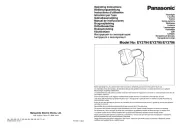
EX-11SB-PN

| Mærke: | Panasonic |
| Kategori: | Ikke kategoriseret |
| Model: | EX-11SB-PN |
Har du brug for hjælp?
Hvis du har brug for hjælp til Panasonic EX-11SB-PN stil et spørgsmål nedenfor, og andre brugere vil svare dig
Ikke kategoriseret Panasonic Manualer

22 December 2025

25 November 2025
10 Oktober 2025
8 Oktober 2025
1 Oktober 2025

18 September 2025
15 September 2025
27 August 2025
26 August 2025
14 August 2025
Ikke kategoriseret Manualer
- Firefriend
- Paladin
- Mytee
- PolyScience
- Worx
- KED
- NaceCare Solutions
- Lund
- MediaMatrix
- Caroline
- Teris
- Toro
- Homekraft
- Faytech
- Planet Audio
Nyeste Ikke kategoriseret Manualer

25 December 2025

25 December 2025

25 December 2025

25 December 2025

25 December 2025

25 December 2025

25 December 2025

25 December 2025

25 December 2025

24 December 2025