B D E F
4321
Powered speaker Analog monitor
*
*
PoE device (hub)
PC
Analog monitor
Microphone
Powered speaker
Microphone
LAN cable
(category 5 or better, straight)
LAN cable
(category 5 or better, straight)
* Can switch to monitor out
(select the [Setup] [Basic] tab, and then select [Monitor out])→
LAN cable (category 5
or better, straight)
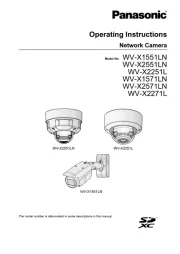
Network Camera
Model No.
Installation Guide
Included Installation Instructions
PGQX1666WA Cs1114-3047 Printed in China
Standard accessories
A
B
C
D
E
F
G
H
I
J
K
L
M
Direction marker for
installation “ TOP” J Desktop cover (accessory)
A Attachment plate (accessory)
Camera
Enclosure
Sub cover
Lens
SD memory
card slot
Major operating controls
q
w
q
w
IMPORTANT:
Note:
☞
ACT
indicator
LINK
indicator
SD ERROR/ABF
indicator
SD memory
card slot
External I/O terminals
EXT I/O*1
Network connector
10BASE-T/ 100BASE-TX*1
Audio cable connector
AUDIO I/O
*1
12 V DC power supply terminal
12V IN*1
SD ON/OFF button
INITIAL SET button
SD memory card
slot cover
Data Matrix:
To our website*3
Image rotation gear Lens*2
Camera xing screw
Built-in
microphone
SD MOUNT
indicator
<Inside view of the SD memory card slot cover (with SD memory card slot cover opened)>
<Inside view of the sub cover (with sub cover removed)>
Making connections
Note:
IMPORTANT:
Connect a LAN cable
Example of LAN cable connector
9 mm
{11/32 inches}
Straight section
30 mm {1-3/16 inches}
40 mm {1-9/16 inches}
13 mm {1/2 inches}
IMPORTANT:
D
D
Caution:
Connect the power cable
D
q
w
Note:
D
IMPORTANT:
IMPORTANT:
E
Connect the alarm input/output cable
E
q
E
w
Note:
E
ALARM IN1
(Alarm input 1)
ALARM IN2, ALARM OUT
(Alarm input 2, Alarm output)
External I/O terminal plug (accessory)E
button
When connecting to a network using a PoE hub
Connecting the microphone to the MIC IN plug of the audio cable
IMPORTANT:
Connecting an external speaker with amplifier to the audio/monitor
output plug of the audio cable
G
<How to remove the audio cable>
Audio cable connector hook
* Press the hook of the con-
nector, and then remove the
audio cable connector.
Note:
⇔
Note:
© Panasonic Corporation 2014
For U.S. and Canada:
Panasonic System Communications
Company of North America,
Unit of Panasonic Corporation
of North America
www.panasonic.com/business/
For customer support, call 1.800.528.6747
Two Riverfront Plaza, Newark, NJ 07102-5490
Panasonic Canada Inc.
5770 Ambler Drive, Mississauga,
Ontario, L4W 2T3 Canada
(905)624-5010
www.panasonic.ca
For Europe and other countries:
Panasonic Corporation
http://www.panasonic.com
Panasonic Corporation
Osaka, Japan
Authorised Representative in EU:
Panasonic Testing Centre
Panasonic Marketing Europe GmbH
Winsbergring 15, 22525 Hamburg, Germany