Network Camera
Model No. WV-SPN531
Please purchase the recommended lens separately.
This manual describes the installation procedures, network camera installation, cable connections, ●
and the angle of view adjustment.
Before reading this manual, be sure to read the Important Information. ●
PGQX1761ZA Cs1014-0 Printed in China
Standard accessories
Important Information ............................... 1 pc.
Installation Guide (this document) ............ 1 set
Warranty card ........................................... 1 set
CD-ROM*1 ................................................ 1 pc.
Code label*2 .............................................. 1 pc.
*1 The CD-ROM contains the operating instructions and different kinds of tool software programs.
*2 This label may be required for network management. The network administrator shall retain the
code label.
The following parts are used during installation procedures.
A Tripod mount base ............................... 1 pc.
C
Safety wire lug
...................................... 1 pc.
E Safety wire ........................................... 1 pc.
F Washer ................................................. 1 pc.
G Spring washer ...................................... 1 pc.
B Power cord plug ................................... 1 pc.
D Wire lug fixing screws
(M2.5 x 8 mm {5/16 inches}) ............. 2 pcs.
(of them, 1 for spare)
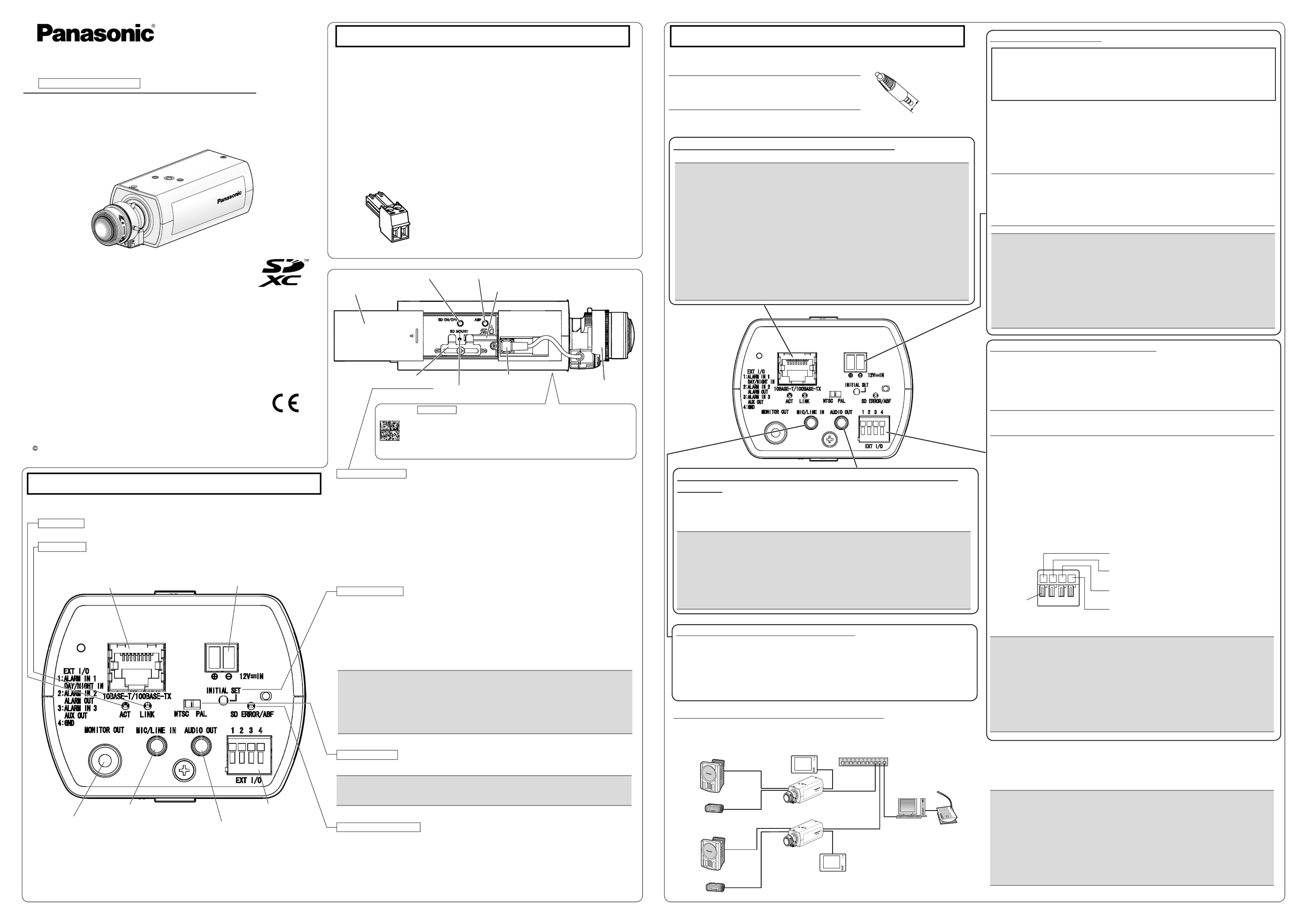
Slide cover
SD ON/OFF button Auto back focus button (ABF)
SD memory card slot
ALC lens connector
SD MOUNT indicator
Clamp for SD memory card Lens (recommended)
Major operating controls When an SD memory card ●*2 is inserted and could Lights off → Blinks green →
be recognized Lights off
When data can be saved after the SD memory card is Lights off → Lights green ●
inserted and the SD ON/OFF button is pressed
When data can be saved to the SD memory card Lights green ●
When the SD memory card is removed after holding down ●
Lights green → Blinks green → Lights off
the SD ON/OFF button for about 2 seconds
When data cannot be saved to the SD memory card because
● Lights off
an abnormality was detected or the SD memory card is
configured not to be used
*1 The detailed specications on the right side in this page describe terminals
with markings.
*2 SDXC/SDHC/SD memory card is described as SD memory card.
Making connections
Turn off each system’s power supply before making a connection. Before making connections,
prepare the required peripheral devices and cables.
Before starting the installation, check the entire system configuration. The following illustration
gives a wiring example of how to connect the camera to the network via a PoE device (hub).
<Required cable>
LAN cable (category 5 or better, straight)
Use a LAN cable (category 5 or better, cross) when directly connecting the camera to a PC.
When connecting to a network using a PoE hub
IMPORTANT:
Connect/disconnect the audio cables and turn on the power of the camera after turning ●
off the power of the audio output devices. Otherwise, loud noise may be heard from
the speaker.
Make sure that the stereo mini plug is connected to this cable. When a monaural mini ●
plug is connected, audio may not be heard.
When connecting a monaural speaker with amplifier, use a locally procured conversion
cable (mono-stereo).
Connect an external speaker with amplier to the audio output
connector
Connect a stereo mini plug (ø3.5 mm) (Audio output is monaural.). Use an external powered speaker.
Output impedance : Approx. 600 Ω (unbalanced) ●
Recommended cable length : Less than 10 m {32.8 feet} ●
Output level : –20 dBV ●
Connect the microphone to MIC/LINE IN
Connect a monaural mini plug (ø3.5 mm).
Input impedance: Approx. 2 kΩ (unbalanced) ●
Recommended cable length: Less than 1 m {3.28 feet} (for microphone input) ●
Less than 10 m {32.8 feet} (for line input)
Recommended microphone: Plug-in power type (option) ●Supply voltage: 2.5 V ±0.5 V ●
Input level for the line input: Approx. –10 dBV ●
Recommended sensitivity of microphone: –48 dB ±3 dB (0 dB=1 V/Pa,1 kHz) ●
IMPORTANT:
Do not connect 2 wires or more directly to a terminal. When it is necessary to con- ●
nect 2 or more wires, use a splitter.
Off, input, and output of the external I/O terminal 2 and 3 can be switched by con- ●
figuring the setting. Refer to the Operating Instructions on the provided CD-ROM
for further information about the EXT I/O terminal 2 and 3 (ALARM IN2, 3) settings
(“Off”, “Alarm input”, “Alarm output” or “AUX output”).
Install external devices so that they do not exceed the rating of the network camera. ●
When using the EXT I/O terminals as the output terminals, ensure they do not ●
cause signal collision with external signals.
IMPORTANT:
The adjustment monitor is used for checking the adjustment of the angular field of ●
view when installing the camera or when servicing. It is not provided for recording/
monitoring use.
Depending on the monitor, some characters (camera title, preset ID, etc.) may not ●
be displayed on the screen.
Use a switching hub or a router which is compliant with 10BASE-T/100BASE-TX. ●
If a PoE hub is not used, each network camera must be connected to a 12 V DC ●
power supply.
When using 12 V DC, power supply from a PoE hub or router is not required. ●
Connect the alarm input/output cable
Connect the cables of external devices to the EXT I/O terminal plug.
q
When connecting an external device, remove 8 mm - 9 mm {5/16 inches - 11/32 inches} of
the outer jacket of the cable and twist the cable core to prevent the short circuit first.
Specification of cable (wire): AWG 20 - AWG 26, Single core, twisted
w
Push down the button of the desired terminal on the external I/O terminal plug with a ball-
point pen, and release the button when the cable of the external device is fully inserted
into the terminal hole.
PoE device (hub)
PC
LAN cable (category 5
or better, straight)
Adjustment monitor
Adjustment monitor
LAN cable
(category 5 or better, straight)
LAN cable
(category 5 or better, straight)
Powered speaker
Microphone
Powered speaker
Microphone
Note:
Check whether the stripped part of the wire is not exposed and is securely connected. ●
<Ratings>
ALARM IN1(DAY/NIGHT IN), ALARM IN2, ALARM IN3 ●
Input specication : No-voltage make contact input (4 V - 5 V DC, internally pulled up)
OFF : Open or 4 V - 5 V DC
ON : Make contact with GND (required drive current: 1 mA or more)
ALARM OUT, AUX OUT ●
Output specication
: Open collector output (maximum applied voltage: 20 V DC)
Open : 4 V - 5 V DC by internal pull-up
Close : Output voltage 1 V DC or less (maximum drive current: 50 mA)
* The default of EXT I/O terminals is “Off”.
SD MOUNT indicator
The MONITOR OUT terminal output can be switched for the NTSC monitor/PAL monitor. ●
IMPORTANT:
This is valid if the [Monitor out] is set to [Switch priority] ([Switch priority] is selected by ●
default).For details, refer to the Operating Instructions (included in the CD-ROM).
NTSC/PAL switch
How to initialize the camera ●
Follow the steps below to initialize the network camera.
q Turn off the power of the camera. When using a PoE hub, disconnect the LAN cable from
the camera. When using an external power supply, disconnect the power cord plug from the
12 V DC power supply terminal.
w Turn on the power of the camera while holding down the INITIAL SET button, and then
keep holding down the button for 5 seconds or more. About 2 minutes later, The camera will
start up and the settings including the network settings will be initialized.
IMPORTANT:
When the camera is initialized, the settings including the network settings will be initial- ●
ized. Note that the CRT key (SSL encryption key) used for the HTTPS protocol will not
be initialized.
Before initializing the settings, it is recommended to write down the settings in advance. ●
Do not turn off the power of the camera during the process of initialization. Otherwise, it ●
may fail to initialize and may cause malfunction.
For U.S. and Canada:
Panasonic System Communications
Company of North America,
Unit of Panasonic Corporation
of North America
www.panasonic.com/business/
For customer support, call 1.800.528.6747
Two Riverfront Plaza, Newark, NJ 07102-5490
Panasonic Canada Inc.
5770 Ambler Drive, Mississauga,
Ontario, L4W 2T3 Canada
(905)624-5010
www.panasonic.ca
For Europe and other countries:
Panasonic Corporation
http://panasonic.net
Panasonic System Networks Co., Ltd.
Fukuoka, Japan
Authorised Representative in EU:
Panasonic Testing Centre
Panasonic Marketing Europe GmbH
Winsbergring 15, 22525 Hamburg, Germany
Installation Guide
Included Installation Instructions
Panasonic System Networks Co., Ltd. 2014
Network connector RJ45
*1
MONITOR OUT terminal
(factory shipment: NTSC monitor)
Microphone/line input connector*1
Audio output connector
*1
EXT I/O terminals*1
12 V DC power supply terminal*1
The component names of the camera are as follows. Refer to the illustration when installing or
adjusting the camera.
When data is being sent via the network camera Blinks green (accessing) ●
When the camera is able to communicate with Lights orange ●
the connected device
LINK indicator
IMPORTANT:
The 12 V DC power supply shall be insulated from the commercial AC power. ●
Be sure to use the power cord plug provided with this product. ●
Be sure to fully insert the power cord plug into the 12 V DC power supply terminal. ●
Otherwise, it may damage the camera or cause malfunction.
When installing the camera, make sure that excessive force is not applied to the ●
power cable.
Be sure to use an AC adaptor compliant with the Specifications (written in the indi- ●
cation label on the bottom side of this unit) regarding power source and power con-
sumption.
Caution:
A READILY ACCESSIBLE DISCONNECT DEVICE SHALL BE INCORPORATED ●
TO THE EQUIPMENT POWERED BY 12 V DC POWER SUPPLY.
ONLY CONNECT 12 V DC CLASS 2 POWER SUPPLY (UL 1310/CSA 223) or ●
LIMITED POWER SOURCE (IEC/EN/UL/CSA 60950-1).
Connect the power cable
Connect the output cable of the DC power supply to the power cord plug ( : accessory).B
q Loosen the screw of the power cord plug, strip 3 mm to 7 mm {1/8 inches to 9/32 inches}
from the end of the wire, twist the stripped part of the wire sufficiently to avoid short circuit,
and then connect the output cable to the power cord plug.
w Tighten the screw of the power cord plug. (Recommended tightening torque: 0.34 N·m
{0.25 lbf·ft})
Note:
Check whether the stripped part of the wire is not exposed and is securely con- ●
nected.
When connecting an external power supply to the camera, use the AWG 16 to ●
AWG 24 single-wired or stranded wired cables.
ALARM IN1, DAY/NIGHT IN
(Alarm input terminal 1, DAY/NIGHT input terminal)
ALARM IN2, ALARM OUT
(Alarm input terminal 2, Alarm output terminal)
ALARM IN3, AUX OUT
(Alarm input terminal 3, AUX output terminal)
GND
External I/O terminal plug
button
IMPORTANT:
Use all 4 pairs (8 pins) of the LAN cable. ●
The maximum cable length is 100 m {328 feet}. ●
Make sure that the PoE device in use is compliant with IEEE802.3af standard. ●
When connecting both the 12 V DC power supply and the PoE device for power ●
supply, 12 V DC will be used for power supply.*
If a 12 V DC power supply and a PoE hub or router are used at the same time, *
network connections may not be possible. In this case, disable the PoE settings.
Refer to the operating instructions of the PoE hub or router in use.
Depending on the PoE device used, if you disconnect 12 V DC while 12 V DC *
power supply and a PoE hub or router are used at the same time, the power supply
may stop, causing the camera to restart.
When the LAN cable is disconnected once, reconnect the cable after around ●
2 seconds. When the cable is quickly reconnected, the power may not be supplied
from the PoE device.
Connect a LAN cable (category 5 or better, straight)
Connect a LAN cable (category 5 or better, straight) to the network connector.
ACT indicator
When ABF (Auto Back Focus) operation is being executed ●
Blinks red (Interval of 1 time/ second)
When the set is being started Lights red ●
When an SD memory card is recognized normally Lights red → Lights off ●
When the ●SD memory card slot is not used or Lights red
an abnormality is detected in SD memory card
after the camera has started
SD ERROR/ABF indicator
Note:
Use audio cables that do not exceed the sizes described ●
in the illustrations.
ø9 mm
{11/32 inches}
Example of audio cable
connector
Data Matrix Bottom side : To our website
Depending on the scanning application used, the Data Matrix may not be
able to be read correctly. In this case, access the site by directly entering
the following URL.
http://security.panasonic.com/pss/security/support/qr_sp_select.html