Pelco Sarix IXP31 Manual
Pelco
Overvågningskamera
Sarix IXP31
Læs nedenfor 📖 manual på dansk for Pelco Sarix IXP31 (61 sider) i kategorien Overvågningskamera. Denne guide var nyttig for 24 personer og blev bedømt med 4.9 stjerner i gennemsnit af 12.5 brugere
Side 1/61

C39 M-B-EN (5/15) 60
Sarix® IXP Series
Indoor Box
User Manual

2

3
Contents
Important Notices ......................................................................................................................................................................... 5
Regulatory Notices 5..............................................................................................................................................................
Radio and Television Interference ....................................................................................................................................... 5
Legal Notice ......................................................................................................................................................................... 5
Video Quality Caution .......................................................................................................................................................... 5
Frame Rate Notice Regarding User Selected Options 5........................................................................................................
Open Source Software 6........................................................................................................................................................
KCC Certification ................................................................................................................................................................. 6
Korean Class A EMC 6..................................................................................................................................................
ESD Warning ....................................................................................................................................................................... 6
Network Topology Statement ....................................................................................................................................................... 6
Legal Notice (Audio Notice) .......................................................................................................................................................... 6
Preface ......................................................................................................................................................................................... 7
1. Product Overview .............................................................................................................................................................. 8
1.1 Dimensions .................................................................................................................................................................... 8
1.2 Physical Characteristics ................................................................................................................................................. 9
2. Installation and Connection ........................................................................................................................................ 10
2.1 Unpacking Everything .................................................................................................................................................. 10
2.2 Installation .................................................................................................................................................................... 10
2.2.1 Checking Appearance ...................................................................................................................................... 10
2. 2 2. Installing the Lens ............................................................................................................................................ 11
2.2.3 Mounting the Camera ....................................................................................................................................... 11
2.2.4 Connecting the Wires ....................................................................................................................................... 11
2.2.5 Adjusting the Focus .......................................................................................................................................... 11
2.2.6 Network Topology ............................................................................................................................................12
2.2.7 System Requirements ...................................................................................................................................... 12
2.3 Connection ................................................................................................................................................................... 13

4
2.3.1 Default IP Address ...........................................................................................................................................13
2.3.2 Connecting from a Computer & Viewing Preparation ....................................................................................... 13
3. Administration and Configuration .............................................................................................................................. 15
3.1 Live .............................................................................................................................................................................. 15
3.1.1 Zoom and Focus Controls ................................................................................................................................ 16
3.2 Settings ........................................................................................................................................................................ 16
3.2.1 System ............................................................................................................................................................. 16
3.2.2 Network ............................................................................................................................................................ 20
3.2.3 Imaging ............................................................................................................................................................. 30
3.2.4 A/V Streams ..................................................................................................................................................... 35
3.2.5 Users ................................................................................................................................................................ 40
3.2.6 Events .............................................................................................................................................................. 44
Specifications ....................................................................................................................................................................... 54
Pelco Troubleshooting Contact Information ...............................................................................................................................59

5
Important Notices
REGULATORY NOTICES
This device complies with Part 15 of the FCC Rules. Operation is subject to the following two conditions: (1) this device may
not cause harmful interference, and (2) this device must accept any interference received, including interference that may
cause undesired operation.
RADIO AND TELEVISION INTERFERENCE
This equipment has been tested and found to comply with the limits of a Class A digital device, pursuant to Part 15 of the FCC
rules. These limits are designed to provide reasonable protection against harmful interference when the equipment is operated
in a commercial environment. This equipment generates, uses, and can radiate radio frequency energy and, if not installed
and used in accordance with the instruction manual, may cause harmful interference to radio communications. Operation of
this equipment in a residential area is likely to cause harmful interference in which case the user will be required to correct the
interference at his own expense.
Changes and Modifications not expressly approved by the manufacturer or registrant of this equipment can void your authority
to operate this equipment under Federal Communications Commission’s rules.
In order to maintain compliance with FCC regulations shielded cables must be used with this equipment. Operation with
non-approved equipment or unshielded cables is likely to result in interference to radio and television reception.
This Class A digital apparatus complies with Canadian ICES-003.
Cet appareil numérique de la classe A est conforme à la norme NMB-003 du Canada.
LEGAL NOTICE
SOME PELCO EQUIPMENT CONTAINS, AND THE SOFTWARE ENABLES, AUDIO/VISUAL AND RECORDING
CAPABILITIES, THE IMPROPER USE OF WHICH MAY SUBJECT YOU TO CIVIL AND CRIMINAL PENALTIES.
APPLICABLE LAWS REGARDING THE USE OF SUCH CAPABILITIES VARY BETWEEN JURISDICTIONS AND MAY
REQUIRE, AMONG OTHER THINGS, EXPRESS WRITTEN CONSENT FROM RECORDED SUBJECTS. YOU ARE SOLELY
RESPONSIBLE FOR INSURING STRICT COMPLIANCE WITH SUCH LAWS AND FOR STRICT ADHERENCE TO ANY/ALL
RIGHTS OF PRIVACY AND PERSONALTY. USE OF THIS EQUIPMENT AND/OR SOFTWARE FOR ILLEGAL
SURVEILLANCE OR MONITORING SHALL BE DEEMED UNAUTHORIZED USE IN VIOLATION OF THE END USER
SOFTWARE AGREEMENT AND RESULT IN THE IMMEDIATE TERMINATION OF YOUR LICENSE RIGHTS
THEREUNDER.
VIDEO QUALITY CAUTION
FRAME RATE NOTICE REGARDING USER SELECTED OPTIONS
Pelco systems are capable of providing high quality video for both live viewing and playback. However, the systems can be
used in lower quality modes, which can degrade picture quality, to allow for a slower rate of data transfer and to reduce the
amount of video data stored. The picture quality can be degraded by either lowering the resolution, reducing the picture rate,
or both. A picture degraded by having a reduced resolution may result in an image that is less clear or even indiscernible. A
picture degraded by reducing the picture rate has fewer frames per second, which can result in images that appear to jump or
move more quickly than normal during playback. Lower frame rates may result in a key event not being recorded by the
system.
Judgment as to the suitability of the products for users' purposes is solely the users' responsibility. Users shall determine the
suitability of the products for their own intended application, picture rate and picture quality. In the event users intend to use
the video for evidentiary purposes in a judicial proceeding or otherwise, users should consult with their attorney regarding any
particular requirements for such use.

6
OPEN SOURCE SOFTWARE
This product includes certain open source or other software originated from third parties that is subject to the GNU General
Public License (GPL), GNU Library/Lesser General Public License (LGPL) and different and/or additional copyright licenses,
disclaimers, and notices.
The exact terms of GPL, LGPL, and some other licenses are provided to you with this product. Please refer to the exact terms
of the GPL and LGPL at http://www.fsf.org (Free Software Foundation) or http://www.opensource.org (Open Source Initiative)
regarding your rights under said license. You may obtain a complete corresponding machine-readable copy of the source code
of such software under the GPL or LGPL by sending your request to digitalsupport@pelco.com; the subject line should read
Source Code Request. You will then receive an email with a link for you to download the source code.
This offer is valid for a period of three (3) years from the date of the distribution of this product by Pelco.
KCC CERTIFICATION
K C A EMC orean lass
ESD WARNING
WARNING: This product is sensitive to Electrostatic Discharge (ESD). To avoid ESD damage to this product,
use ESD safe practices during installation. Before touching, adjusting or handling this product, correctly attach
an ESD wrist strap to your wrist and appropriately discharge your body and tools. For more information about
ESD control and safe handling practices of electronics, please refer to ANSI/ESD S20.20-1999 or contact the
Electrostatic Discharge Association (www.esda.org).
Network Topology Statement
IMPORTANT NOTE. PLEASE READ. The network implementation is shown as a general representation only and is not
intended to show a detailed network topology. Your actual network will differ, requiring changes or perhaps additional network
equipment to accommodate the system as illustrated. Please contact your local Pelco Representative to discuss your specific
requirements.
Legal Notice (Audio Notice)
NOTE: Improper use of audio/visual recording equipment may subject you to civil and criminal penalties. Applicable laws
regarding the use of such capabilities vary between jurisdictions and may require, among other things, express written consent
from the recorded subjects. You are solely responsible for insuring strict compliance with such laws and for strict adherence to
any/all right of privacy and personality .
WARRANTY STATEMENT
For information about Pelco's product warranty and thereto related information, refer to
www.pelco.com/warranty.

7
Preface
This user manual is to be used as a reference for the installation and manipulation of the camera unit including features,
functions, and a detailed explanation of the menu tree.
This manual provides the reader with the following information:
the main functions and system requirements of the unit Product Overview:
instructions on unit installation and wire connections Installation and Connection:
the main menu navigation and controls explanationsAdministration and Configuration:

8
1. Product Overview
1.1 Dimensions
VALUES PARENTHESES ARE INCHES; ALL HERS ARE IN OT
CENTIMETERS.
F 1-1: P IGURE HYSICAL DIMENSIONS

9
1.2 Physical Characteristics
F 1-2: C C F IGURE AMERA ONNECTIONS AND EATURES
1. Lens
2. To record images when events happen. Micro-SD Card:
3. Using a small tool, such as a paper clip, hold down the reset button longer than 5 seconds to reset the camera to Default:
factory defaults.
4. Using a small tool, such as a paper clip, press the reset button briefly and release to restart the camera. Reset:
5. Digital I/O Connectors
A. Alarm In: Using the and (ground) ports, connect to an external device that can trigger alarm inpu signals. “IN” “ ” t
B. Alarm Out: Using the OUT COM ports, connect to an external device to be triggered through alarm output “ ” and “ ”
signals.
C. Audio In: Using the + and - ports, connect to an external device like microphone that receives sound for the “ ” “ “ a
camera.
6. The LED lights on when power is applied.Power LED:
7. Supports 24 VAC as the power source. 24 VAC Power:
8. Connects the camera to the IP network. Also supplies power to the camera through the network RJ-45 Network Port:
using PoE. If PoE is not available, the camera is prewired for 24 VAC.
9. Ethernet Activity LED: Flashes green to indicate that data is being transmitted/ received by the camera.
10. Glows solid amber to indicate that a live connection is established.Ethernet Link LED:
11. Both top and bottom of the camera housing have one mount screw hole for mounting the camera. Mount Screw Hole:
Use a standard 1/4”-20 screw to mount the camera in the desired location.

10
2. Installation and Connection
2.1 Unpacking Everything
Check all items in the product box against the order form and the packing slip. In addition to this manual, the items below are
included in the packing box:
One indoor b camera ox
One resource CD
One printed quick installation guide
One lens ring adaptor
24V and alarm connectors
One wrench pin Torx
Please contact your dealer if any items are missing.
2.2 Installation
Following tools might help you complete the installation:
a drill
screwdrivers
wire cutters
2.2.1 Checking Appearance
Although the protective materials used for the packaging should be able to protect the unit from most accidents during
transportation, check the unit and its accessories for any visible damage Remove the protective film to check items . in
accordance with the list . in 2.1 Unpacking Everything

11
2. 2 2. Installing the Lens
Att Lens Type is DC Iris. ach your lens onto the camera’s lens mounting ring.
-Mount lensCS : Attach the lens to the camera directly. Screw the lens onto the lens mount. Be careful to prevent
dust from entering the space between the lens and the imager. If necessary, use clean, compressed air to remove
any foreign matter (refer to the instructions shipped with the lens).
NOTE: Make sure the lens does not touch the camera imager when installed.
F 2-1: I L IGURE NSTALLING THE ENS
2.2.3 Mounting the Camera
Use a standard 1/4 -20 screw to mount the camera in the desired location. The maximum thread depth is 6.4 mm (0.25 ”
inches). The camera can be mounted from either the top or bottom, depending on the type of camera mount used in your
installation.
NOTE: When installing inside an enclosure, mount the camera in an inverted position to allow easy access to the service port.
Use the camera software to reconfigure the camera orientation for normal operation.
2.2.4 Connecting the Wir es
This unit supports one of the following options as power supply. Refer to in Figure 1-2: Camera Connections and Features
1.2 Physical Characteristics to connect the wires.
VAC24 : Connect 24V (~) cables to terminals ~ 24 VAC
PoE: Connect the - network connector to a PoE compatible network device that has supplied power through the RJ 45
Ethernet cable.
(Optional) Insert audio cable and alarm cable to the unit, and connect the network cable to the RJ- network port of 45
a switch.
Caution
To avoid damage to the unit, never connect more than one type of power supply (PoE IEEE802.3
Ethernet Class 3 or AC 24V power plug) at the same time.
2.2.5 Adjusting the Focus
Focus the lens:
1. View the camera image using the browser (refer to 2.3 Connection).
2. Adjust the lens zoom and focus manually to the desired field of view (refer to the instructions shipped with the lens).
3. Adjust the lens focus by using the focus controls in the user interface.

12
2.2.6 Network Topology
The camera can deliver video images and audio in real time using the Internet and Intranet. It's equipped with Ethernet RJ-45
network interface.
F 2-2: N T T IGURE ETWORK OPOLOGY YPE Ⅰ
Ⅰ
Ⅰ
ⅠⅠ
F 2-3: N T T IGURE ETWORK OPOLOGY YPE Ⅱ
Ⅱ
Ⅱ
ⅡⅡ
2.2.7 System Requirements
The table below lists the minimum requirements to implement and operate a unit. Network and processor bandwidth limitations
might cause the video stream to pause or appear pixilated when additional Web-interface users connect to the camera.
Decrease the images per second (ips), resolution, compression, or bit rate settings of the Web interface video streams to
compensate for network/processor limitations.
T 2- S R ABLE 1: YSTEM EQUIREMENTS
System Hardware
CPU
Intel® Pentium® 4 microprocessor, 2.4GHz or equivalent
RAM
1 GB or above
Monitor
Minimum of 1024 x 768 resolution, 16- or 32-bit pixel color resolution
System Software
Operating System
Microsoft® Windows® XP, Vista 32 and 64 bit, Win7 32 and 64 bit
Browser
Internet Explorer® 9.0, Apple® Safari® 7.0.6, Mozilla® Firefox® 31.0, Google® Chrome™
37.0.2062.124 m and later
M Player edia
Pelco Media Player or QuickTime® 7.6.5 for Windows XP, Windows Vista, and Windows 7; or
QuickTime 7.6.4 for Mac OS X 10.4 (or later)
Unit
Power Supply
AC 24V / PoE
Note
1. All the installation and operations should comply with your local electricity safety rules.
2. Pelco Media Player is recommended for control, smoothness, and reduced latency as compared to
QuickTime. The PMP is downloadable from Pelco web site www.pelco.com/mediaplayer. :
3. This product is not compatible with QuickTime version 7.6.4 for Windows XP or Windows Vista. If
you have this version installed on your PC, you will need to upgrade to QuickTime version 7.6.5.

13
2.3 Connecti on
2.3.1 Default IP Address
The default IP address is and sub mask is . When setting the default IP address of unit’s 192.168.0.20 255.255.255.0
192.168.0.20, the camera will check to see if that address is already in use it will bump the last octet of the address by 1 if and
it is. The bump last octet of IP Address by 1 will continue until an unused IP address is found.
However, if you have a DHCP server in your network, the unit would obtain an IP address automatically from the DHCP server
so that y . The factory default is DHCP the 192.168.0.20 IP address ou don’t need to change the camera’s IP address On and
assignment only occurs when the camera is set for DHCP but a DHCP server does not respond to request for an IP address.
2.3.2 Connecting from a Computer & Viewing Preparation
2.3.2.1 ing Pelco Device Utility Software to Get Camera s IP Address Us ’
Pelco Device Utility software is a utility program that helps users to manage and configure the camera. Use the utility to find
the IP address since the default option is to obtain an IP address via DHCP and therefore the IP address will NOT be known.
Steps to get the utility program running are listed below.
1. Follow the installation instructions to finish installing the Device Utility to the computer.
2. Log in to the Device Utility by entering the camera s User name and Password. In the window, enter the default user ’
name: and password: then click button to log in. admin admin, Enter DU2
3. In the Manage Devices page, you can click Refresh Device List or Add New Device to search for the devices.
4. From the Device List, you can get series information about the camera, IP Address included.
For more information about using the Device Utility, click this green icon " " on the upper-right corner of the Device Utility
page.
2.3.2.2 Connecting from a Computer
1. Check if the networking is available between the unit and the computer. Ping the default IP address Start a co and . mm
prompt (Windows: from the Start Menu, select Program. Select Accessories and choose Co and Prompt.), and type mm
“Ping 192.168.0. 0”. If the message “Reply from…” appears, it means the connection is 2 available.
2. Start Internet Explorer and enter IP address: . A login window should pop up In the window, enter the 192.168.0.20 .
default user name: and password: to log in. admin admin
NOTE: If you do not know the camera’s IP address, you can locate it using the Pelco Device Utility software (refer to 2.3.2.1
Using Pelco Device Utility Software to Get Camera’s IP Address).
Further administration on the unit can be found in Administration and Configuration “3. ".
F 2-4: L WIGURE OGIN INDOW

14
2.3.2.3 Viewing Preparation
Images of the unit can be viewed through Microsoft Internet Explorer 8 or later. Before viewing, follow these steps to enable
the display.
1. Enable Cookies On the tab, move the settings slider to or . Privacy Low Accept All Cookies
2. Change Security in and click to open the Internet options Custom Level Security Settings Internet Zone – screen.
NOTE: Intranet If the camera operates inside the intranet, click the of icon. If the camera operates outside of the intranet,
click the icon. Internet
3. Scroll down to the ActiveX controls and plug-ins radio buttons and set as follows:
【
【
【
【【 】
】
】
】】Download signed ActiveX controls Prompt (recommended)
【
【
【
【【 】
】
】
】】Download unsigned ActiveX controls Prompt
【
【
【
【【 】
】
】
】】Automatic prompting for ActiveX controls
Enable
【
【
【
【【 】
】
】
】】Run ActiveX controls and plug-ins Enable
【
【
【
【【 】
】
】
】】Script ActiveX controls marked safe for scripting* Enable
4. Press to save the settings. OK
5. Close all Microsoft Internet Explorer Windows and restart a new window. This will allow the new settings taking effect.
6. Type your setting IP address into the browser.
7. en. Then you should be able to see the camera image scre

15
3. Administration and Configuration
3.1 Live
Simply click on on the top right side of the browser window while accessing the IP address of the unit, and a live video is Live
displayed directly in the browser window. When clicking , a window will pop up for configuring on Settings “ ”, System
“ ” “ ” “ ” “ ” “ ”Network , Imaging , A/V Streams , Users , and Events . Please refer to on page for more information. 3.2 Settings 16
The current logged in identity shows to the right of the Click on of the administration window Help. Logout admin and
configuration will return to the camera image screen.
* Figures of are taken from the 3MP model for web interface introduction purposes. 3. Administration and Configuration
Options within each item may differ slightly among series products and the differences will be marked in . a NOTE
Below are definitions of the tabs on the window. Live
Select Stream: Selects the viewable video stream that is displayed in live view (primary or secondary) and
selects unicast or multicast settings.
Maximize Viewing Area: Scales the image to the full size of the browser. To resize the video pane to normal
view, click the Show Toolbar button in the upper-right corner of the window.
Open Stream in New Window: Opens the video in a scalable, independent window. Opening the video in a
separate window allows you to view the video while other applications are running. This window can be
minimized, maximized, or closed using the title bar buttons of the active window. The window can also be
resized to your specifications by dragging the lower-right corner of the window.
F 3-1: L V IGURE IVE IEW

17
F 3-3: S S IGURE YSTEM ETTINGS
Generate System L og
1. Click the System tab.
2. Click the Generate System Log button to create a system log that can be used by Pelco Product Support for
troubleshooting.
Contact Pelco Product Support at 1- -289-9100 (USA and Canada) or +1-559- -1981 (international). 800 292
Reboot Camera
1. Click the System tab.
2. Click the Reboot Camera button to restart the camera. Rebooting the camera does not change the configured
camera settings.
Restore All Camera Defaults
This process cannot be undone; all user and custom settings will be lost.
1. Click the System tab.
2. Click the Restore All Camera Defaults button to rest ore the camera’s factory default settings.
NOTE: If the camera is not connected to a Dynamic Host Configuration Protocol (DHCP) network, the IP address
settings for the camera will be lost and the server will not recognize the camera. DHCP On is the default setting for the
camera IP address.

18
3.2.1.1 General Settings
F 3-4: G S IGURE ENERAL ETTINGS
Device Name
Change the Device Name by following steps:
1. Click the box and highlight the text. Device Name
2. Type a user-friendly name into the box (2 to 64 characters). A user-friendly name makes it easier to Device Name
recognize the device on the network. Examples of user-friendly names are Front Door, Lobby, or Parking Lot.
3. Click Save to save the new device name, or click Reset to restore to the previously saved device name.
Time Settings
If the camera is connected to a network that has time server properties Dynamic Host Configuration Protocol (DHCP)
configured, the camera will synchronize automatically with the time server. If the DHCP network’s time server properties are
not configured or the network does not have a time server, you need to configure the time settings manually.
1. Type the IP address of the time server in the field. The time server is an external server that uses Time Server
Network Time Protocol (NTP) to synchronize the camera date and time settings.
2. Select the Time Zone option. Select the continent and the region that are closest to the camera’s location from the
Time Zone drop-down menus.
NOTE: If your location observes a form of daylight saving time, the system will automatically change the time on
the associated dates.

19
3. Select the format in which the date and time will appear from the Display Format drop-down field if you have opted
to show the Date/Time Overlay.
4. Click the Save button to save the settings, or click the Reset button to clear all of the information you entered
without saving it.
Text Overlay
1. Configure the text overlay settings:
Set the background color for the text overlay as black or transparent. Text color for the Background:
transparent background can be also customized from the drop-down menu when the transparent background
option is selected.
Four content options can be selected to display from the drop-down menu: Date/Time, Camera Content:
Name, Camera Name + Date/Time, and Custom Text. The blank text field, which is for inputting desired text
by users, shows only when Custom Text option is selected.
NOTE: Multiple content options can display simultaneously.
Four positions can be selected to display content overlays: Top Left, Top Right, Bottom Content Position:
Left, and Bottom Right. A maximum of three positions can be enabled simultaneously.
2. Click the Save button to save the settings, or click the Reset button to clear all of the information you entered
without saving it.
3.2.1.2 Backup & Restore
F 3-5: B R S IGURE ACKUP AND ESTORE ETTINGS
Backup
Once the camera settings have been configured for optimal scene display, use the backup feature to save the camera
settings.
Restore
If the camera settings are changed and inadvertently result in a less desirable image, use the restore setting to restore the
camera to the previously saved settings.
NOTE: This feature is not intended for the configuration of multiple units or for firmware upgrades.
3.2.1.3 System Information
The System Information page fields are read-only and include the firmware version, hardware version, model number, and
serial number of the system are revealed here as below figure. This information is typically required by Pelco Product Support
for troubleshooting purposes.

20
F 3-6: S I IGURE YSTEM NFORMATION
3.2.1.4 Firmware Update
Users can update system firmware if available. All camera motions will shut down during firmware update. Please close any a
other screens before firmware update. Never disconnect power or LAN cable during the firmware update process. a
Disconnecting power during a firmware update will cause the update to fail. It takes approximately 3 minutes for the unit to
reboot after the firmware update process .
F 3-7: F U IGURE IRMWARE PDATE
3.2.2 Network
Use the Network tab to change the camera’s general network settings, select the Secure Sockets Layer (SSL) settings, enable
Secure Shell (SSH), configure 802.1x port security settings, choose SNMP Server Firewall mode and enable FTP access to
this camera.
F 3-8: N C IGURE ETWORK ONFIGURATION

21
3.2.2.1 General
Set the General Network Settings for network communication settings.
F 3-9: G N S IGURE ENERAL ETWORK ETTINGS
System Settings
Settings under the System Settings are Hostname, HTTP Port, HTTPS Port, and RTSP Port. Contact your network
administrator before changing port settings to ensure that your port settings do not conflict with your network infrastructur e.
Hostname
1. Click in the box and highlight the text.Hostname
2. Type a user-friendly name into the Hostname box (1 to 21 characters) using any combination of alphanumeric
characters. A user-friendly name makes it easier to recognize the device on the network.
3. Click the Save button to save the settings, or click the Reset button to clear all of the information you entered
without saving it.
HTTP Port
NOTE: The HTTP port number must remain at the default setting (80) when connecting to a Pelco video management
system (VMS) platform. If connecting to a Pelco VMS, do not change the HTTP port setting.
1. e Click in th HTTP Port box and highlight the text.

22
2. Type the new port number in the field. The default port for HTTP communications is . HTTP Port 80
3. Click the Save button to save the settings, or click the Reset button to clear all of the information you entered
without saving it.
HTTPS Port
NOTE: The HTTPS port is not configurable unless you have set SSL Mode to Optional or Required and installed a
security certificate.
1. Click in the box and highlight the text. HTTPS Port
2. Type the new port number in the field. The default port for HTTPS communications is . HTTPS Port 443
3. Click Save. If you have changed the setting in error, you can click reset to revert to the previously saved setting.
RTSP Port
1. Click in the box and highlight the text. RTSP Port
2. Type the new port number in the field. The default port for RTSP communications is . RTSP Port 554
3. Click the Save button to save the settings, or click the Reset button to clear all of the information you entered
without saving it.
IPv4 Settings
Enable or disable the server. DHCP automatically assigns an IP address to Dynamic Host Configuration Protocol (DHCP)
the device if there is a DHCP server on the network.
the IP address, subnet mask, gateway, and DNS server settings are read-only text. If DHCP is set to On,
these settings must be manually changed. If DHCP is set to Off,
Change the following network settings as required:
1. The address of the camera connected to the network. IP Address:
2. The address that determines the IP network that the camera is connected to (relative to its Subnet Mask:
address).
3. The router that accesses other networks. Gateway:
4. The addresses of the dedicated servers that translate the names for Web sites and hostnames into DNS Servers:
numeric IP addresses.
5. Click the Save button to save the settings, or click the Reset button to clear all of the information you entered
without saving it.
Endura Connectivity
In order to connect with the Pelco NVR Endura, please choose which communication method to be adopted for connectivity
from the following 2 options:
In general, Endura broadcasts its SM IP Address to the camera Listen for Endura SM system availability broadcast:
so that a stable connection can be maintained between Endura system and the camera.
Associate with specific Endura SM system: Under certain cases, the camera is unable to receive broadcast from
Endura system and therefore is in need of a SM IP Address assigned specifically by user for connectivity.

23
Configuring IPv6 Settings
The device will accept up to sixteen IPv6 addresses, three IPv6 DNS servers, and three IPv6 gateways.
There are two configuration modes for IPv6 address assignments:
Enables automatic configuration using router advertisement. Additional configuration can be provided over Auto:
DHCPv6 (if available on your network). Selecting Auto mode still allows you to manually configure additional IPv6
addresses, DNS servers, and gateways.
Provides a link-local IPv6 address for the device and allows you to assign up to 16 static IPv6 addresses Manual Only:
to the device.
1. Place your mouse pointer over the Network tab.
2. Select General from the drop-down menu.
3. Select On for IPv6.
4. Select a Configuration Mode from the drop-down box. Selecting Auto allows the device to configure the remaining
IPv6 settings automatically, rendering the remaining steps optional.
5. Provide static, unicast addresses in the Manual IP Addresses box. Each address requires a prefix, and it (Optional)
must be input using the format . Manual IP addresses without prefix information will be rejected. prefix/IPv6Address
6. Provide the addresses of DNS servers that are not configured automatically in the Manual DNS Servers (Optional)
box.
7. Provide the addresses of gateways that are not configured automatically in the Manual Gateways box. (Optional)
NOTES:
The device will not accept multicast, localhost, or undefined IPv6 addresses.
-local addresses are not supported for DNS. Link
Manually specified DNS servers supersede automatically discovered DNS servers.
Manually specified DNS servers are not validated by the device; verify any manually specified DNS servers before
saving IPv6 settings.
Manually specified gateways must be on the same network as the device’s IPv6 addresses. Behavior for a gateway that
is not on the same network as the device’s IPv6 addresses is undefined.
Some video management systems (VMS), including Pelco VMS systems, do not support connections to cameras and
encoders over IPv6.

24
3.2.2.2 SSL
To ensure security on the Internet, all Web browsers provide several security levels that can be adjusted for sites that use SSL
technology to transmit data. encrypts communications, making it difficult for unauthorized users to intercept and view user SSL
names and passwords.
SSL requires signed certificates to determine if the Web browser accessing the camera has the required authentication. The
camera can generate a certificate signing request (CSR) that can be sent to a certificate authority for a signature (for example,
VeriSign®), or it can generate a self-signed certificate using the option. Generate Self-Signed Certificate
F 3- : C IGURE 10 SSL ONFIGURATION
SSL Configuration
Select one of the following modes:
A signed Secure Sockets Layer (SSL) certificate must be installed, and a secure URL that begins with the Required:
protocol name “https:” must be used to access the camera. Sensitive data is always encrypted during transmission. A
URL that begins with the “http:” protocol rather than the “https:” protocol will be redirected to the secure URL
automatically.
NOTE: Beginning with firmware version 1.8.2, this field cannot be modified in the Web browser. To select or clear the
Required mode, you must use the ONVIF or Pelco API call. Doing so avoids placing the camera into a mode in which it
would no longer work with a connected VMS system.
A signed SSL certificate must be instalOptional: led, but a secure URL that begins with the protocol name “https:” is
optional when accessing the camera. You can also access the camera using a standard URL with the “http:” protocol, but
sensitive data is not encrypted during transmission. To ensure that sensitive data is encrypted, you must use a secure
URL with the “https:” protocol.
Turns off access to the Web client through SSL. Sensitive data will not be encrypted during Disabled (default):
transmission.
NOTE: If the SSL mode is set to disabled, you cannot access the camera using a URL that begins with an “https:”
protocol. Your Web browser displays an error message if you do not type the camera URL correctly.
Refer to the following sections for more information:
• Generating Self-Signed Certificate
• Generating Certificate Request
Certificate
Generating Self-Signed Certificate
1. Click the button located at the bottom of the Configuration page. The Select Install New Certificate SSL
Certificate Install Method option buttons appear on the page.

25
F 3-11: S C I M IGURE ELECT ERTIFICATE NSTALL ETHOD OPTION
2. Select the “ ” option, and then click . The “Generate Self-signed Certificate Next Self-signed Certificate
Information Form” opens.
F 3-12: G S -S C C IGURE ENERATING ELF IGNED ERTIFICATE ONFIGURATION
3. Fill in all of the fields, and then click . The following progress message appears on the page: Generate Certificate
“ …” After Loading data a while, the certificate is uploaded to the device.
4. After the certificate is uploaded, select the desired mode.
5. Click Save.
NOTE: Self-signed certificates are valid for one year. The certificate’s expiration date is listed in the Installed Certificate
information section. If the certificate has expired and you attempt to access the camera using a secure URL, the Web
browser displays a message. Repeat this procedure to generate and upload a new certificate.
Generating Certificate Request
1. Click the button located at the bottom of the SSL Configuration page. The Select Certificate Install New Certificate
Install Method option buttons appear on the page.
2. Select , and then click Generate Certificate Request Next Certificate Request Form. The “ ” opens.
F 3-13: G C R IGURE ENERATING ERTIFICATE EQUEST
3. Fill in all of the fields, and then click . The following progress message appears on the page: Generate Request
“Generating certificate signing request, please wait…”
4. Send the CSR, which looks like an encrypted block of undecipherable text, to a third-party certificate authority of

26
your choice for a signature.
5. After you receive the signed certificate, click the Install Certificate button to upload the signed certificate to the
device.
6. After the certificate is uploaded, select the desired mode.
7. Click Save.
NOTE: Depending on the third-party certificate authority that signed your certificate, you might need to renew your
certificate after a specified amount of time. Consult the certificate authority for more details.
Upload Certificate
1. Click the button located at the bottom of the SSL Configuration page. The Select Certificate Install New Certificate
Install Method option buttons appear on the page.
2. Select , and then click Upload Certificate Next Certificate. The “ ” opens.
F 3-14: U C IGURE PLOAD ERTIFICATE
3. Choose the Certificate you want to upload and then click button. The following progress message appears Upload
on the page: “ …” Loading data
4. After the certificate is uploaded, select the desired mode.
5. Click Save.
Delete Certificate
1. Once you successfully upload a certificate, button will appears at the bottom of the SSL Delete Certificate
Configuration page.
2. If you want to delete the certificate, click the The following progress message appears on the Delete Certificate,
page: “ …” Deleting certificate file
3. Click Save.
3.2.2.3 SSH
SSH is a user-enabled protocol that allows Pelco Product Support to log on to and service the camera for advanced
troubleshooting purposes.
From this page, users with the appropriate permissions can enable or disable SSH access to the camera.
F 3- : E S S IGURE 15 NABLING ECURE HELL

27
SSH Settings
1. Select the check box. Enabled
2. Click in the box and type a password (4 to 16 alphanumeric characters). Passwords are case-sensitive. Password
NOTE: The default username is “root” and cannot be changed. The username and password are required when
accessing the camera through a third-party SSH client.
3. Click in the “ ” box and retype your password.Re-type Password
4. Click the Save button to save the password and enable SSH, or click the Reset button to clear all of the information
you entered without saving it.
3.2.2.4 802.1x
802.1x is a port security that authenticates devices that want to establish a point- -point access through a wired or wireless to
port using Extensible Authentication Protocol (EAP). This port-based authentication method prevents unauthorized access to a
Local Area Network (LAN) through a physical port. For example, when a device is connected to a network port, the network
switch will ask the device for authentication.
If the credential is accepted when the device sends a credential to the network switch, the network switch will open the port for
normal use.
If authentication fails, the device is prevented from accessing information on the port.
F 3- : C 802.1 P S S IGURE 16 ONFIGURING THE X ORT ECURITY ETTINGS
802.1x Port Security
WARNING: To prevent network conflicts, contact your network administrator before configuring the 802.1x port security
settings.
1. Select the option for the 802.1x Port Security. The default setting for 802.1x is . On Off
2. Select the Extensible Authentication Protocol (EAP) method from the Protocol drop-down menu. Supported EAP
methods include , , EAP-MD5 EAP-TLS, EAP-TTLS and EAP-PEAP.
3. Type the information required for the selected 802.1x authentication method.
4. Connect the PC to an 802.1x secured switch that has the same method. EAP
5. Click the Save button to save the settings, or click the Reset button to clear all of the information you entered
without saving it.
3.2.2.5 SNMP
SNMP is an application layer protocol used to manage TCP/IP-based networks from a single workstation or several
workstations. The camera supports SNMP versions 2c and 3 and can be configured to send data using a trap.

28
F 3-17: SNMP C IGURE ONFIGURATION
SNMP Configuration
WARNING: The Simple Network Management Protocol (SNMP) settings are advanced controls. Consult your network
administrator to obtain the required information to configure SNMP settings.
No SNMP Server
None disables the SNMP configuration and is the default setting.
CONFIGURING SNMP V2C
1. Select as the SNMP Version. V2c
2. Type the community name in the Community String box. The default name for t he Community String is “public.”
3. Configure the Trap Configuration settings.
Type the host name or IP address of the recipient of the trap message. Address:
Type the name of the community that should receive the trap message. Community String:
4. Click the Save button to save the settings, or click the Reset button to clear all of the information you entered
without saving it.
CONFIGURING SNMP V3
1. Select as the SNMP Version. V3
2. Type the SNMP user name in the field. SNMP User
3. Select the encryption algorithm for authentication from the drop-down menu: None, MD5, or SHA. Authentication
If you use authentication method MD5 or SHA, type a password in the text box to the right of the selected
Authentication encryption.
4. Select the privacy encryption algorithm setting from the drop-down menu: None, DES, or AES. If you use Privacy
privacy method DES or AES, type a password in the text box to the right of the selected Privacy encryption.
5. Configure the address for the . The Address is the host name or IP address of the recipient of Trap Configuration
the trap message.
6. Click the Save button to save the settings, or click the Reset button to clear all of the information you entered
without saving it.

29
NOTE: SNMP V2c and SNMP V3 configuration settings are independent of each other, but only one SNMP version can
be active at a time.
3.2.2.6 Firewall
Set the function. A firewall is a system or group of systems that manages access between two networks. Firewall
F 3- : F C IGURE 18 IREWALL ONFIGURATION
Firewall
1. Select or mode to enable this function. The default setting is Allow Deny Off.
2. Type IP address in the field and select protocols. It is carried out over two transport layer protocols: TCP Address
(Transmission Control Protocol) and UDP (User Datagram Protocol)
a connection-oriented, reliable-delivery, robust and high performance transport layer protocol. TCP:
a connectionless protocol, it is efficient protocol for some services and is resourceful but difficult to UDP:
secure.
3. Click the Save button to save the settings, or click the Reset button to clear all of the information you entered
without saving it.
3.2.2.7 F TP
This page will enable or disable access to this camera. In this page, users can activate a FTP Server to access the SD FTP
card for recordings. the use this function. Enabled FTP and
F 3- : F S IGURE 19 TP ETTINGS

30
FTP Settings
1. Select the check box to activate the FTP function, and follow the following procedures to set Enabled
up related settings.
2. Enter a if activated the FTP function. Username
3. Enter a associated with the . Password Username
4. to confirm it. Re-type Password
5. Set the number of maximum connections by entering a number in the field. Max Connections
NOTE: This is the maximum of FTP Client connections, not the maximum of IE Window’s connections.
3.2.3 Imaging
Use the Imaging tab to change the camera’s general image settings, adjust the camera exposure, program the focus
mechanism, or define window blanking privacy areas.
F 3- : I S IGURE 20 MAGING ETTINGS
3.2.3.1 General
General imaging settings include adjustments for camera orientation and digital processing.

32
F 3- : E S IGURE 22 XPOSURE ETTINGS
Exposure
Priority Preset
Select or as the exposure priority. The Motion setting increases exposure time to reduce motion Motion Low Noise
blurring in low light. The Low Noise setting decreases exposure time and adjusts frame rate for improved noise reduction
in low light scenes.
Flicker Correction
Flickering by fluorescent light can be reduced by selecting “50Hz” if the power frequency is 50Hz, “60Hz”, if 60Hz.
Day/Night
The Day Night Auto mode setting automatically controls the IR cut filter depending on the Transition Level and Transition
Detect Time settings.
Auto
1. Determines when the camera changes from day mode (color) to night mode (black-white). Move Transition Level:
the slider to the left or right to change the transition level to a lighter or darker setting. Select a lighter transition
level setting if you want the camera to change modes at a high lux setting. Use the default setting of 4 for normal
day/night operation. Use a darker transition level to change modes at a low lux setting.
T 3-1. L T P I L ABLE UX RANSITION OINTS FOR NCANDESCENT IGHTING
Transition Level Setting
Day to Night Transition Point
Lighter
Darker
1
1.0 ~ 2.0 lux
2
0.50 ~ 1.0 lux
3
0.25 ~ 0.50 lux
4
0.125 ~ 0.25 lux
5
0.0625 ~ 0.125 lux
2. Transition Detect Time (sec): Controls the length of time the camera is exposed to a light level before it changes
to color or black-white mode.
This setting is useful for dark scenes where a bright light is momentarily introduced in the scene (for example,
when a car with its headlights turned on passes the camera scene).

33
Manual
1. Day: Day Day If mode selected, the camera is forced to stay in mode all day.
2. mode selected, the camera is forced to stay in mode all day. Night: If Night Night
3.2.3.3 Focus
Focus sets the back focus to the center focal point of the scene. The camera can be configured to back focus automatically or
manually. Auto focus automatically back focuses the camera on the subject in the center of the scene. Manual focus turns off
the auto focus mechanism and locks the camera at a user-specified position. The manual focus setting is recommended only
for indoor applications that have a single, unchanging primary light source. The Focus page also includes Full Range
Auto-Focus Quick Auto-Focus Restore Settings to Defaults, , and a .
F 3- : F S IGURE 23 OCUS ETTINGS
Focus
Auto Focus
1. The camera is programmed to run a quick automatic focus sequence when the Temperature Change Refocus:
internal temperature sensor of the camera detects an environmental temperature change of 41°F (5°C). This focus
sequence adjusts the center focal point of the scene to maintain optimal focus. The default setting is ; select Off On
to turn this setting. on
2. Day/Night Switch Refocus: Off The default setting for the Day/Night Switch Refocus is . Select On if the camera’s
focal length is greater than 25 mm or the night scene uses mostly IR lighting. The best method to determine if the
day/night refocus should be enabled is to test the camera with the daytime light conditions, and then test it again
with the nighttime light conditions.
When enabled this setting refocuses the camera when the camera changes from day mode (color) to night On
mode (black-white) or vice versa. For example, if the camera changes from day mode to night mode, the imager
automatically adjusts the back focus for the change in light.
3. If required, use one of the following buttons to adjust the focus:
The camera starts a full-range search to find the optimal focal point for the scene. Full Range Auto-Focus:
The camera searches for the optimal focal point in a limited range. Quick Auto-Focus:
The camera resets the auto focus to the factory default setting. Restore Settings to Defaults:
Manual Focus
Select Mode. Two sliders will appear, one for , the other for Manual Day Manual Focus Position Night Manual Focus
Position. Each slider will show a value that is the best focus position for the camera during the day and night.

34
F 3- : M F IGURE 24 ANUAL OCUS
1. Day Manual Focus Position: Day Manual Focus If you need to fine-tune the daytime focus, slightly move the
Position slider to the left or right.
2. If you need to fine-tune the nighttime focus, slightly move the Night Manual Focus Position: Night Manual
Focus Position slider to the left or right.
3. If required, click the button to reset the focus to the factory default setting.Restore Settings To Defaults
3.2.3.4 Window Blanking
Window blanking is used to conceal user-defined privacy areas. A blanked area appears on the screen as a solid gray
window. The camera can handle up to four blanked windows as long as the total blanked area does not exceed 50 percent of
the field of view.
F 3- : W B S IGURE 25 INDOW LANKING ETTINGS
Window Blanking
Window Blanking On
1. Draw a window in the Live Preview area of the page:
a Hold down the left mouse button.
b Drag the mouse diagonally across the area you want to blank.
c A color-coded box appears in the Edit Window section of the page that is the same color as the window drawn
in the Live Preview area.

36
F 3- : A/V S IGURE 27 TREAMS
3.2.4.1 Custom Video Stream Configuration
The Video Configuration page allows you to customize the compression, resolution, image rate, and bit rate of the video
streams. The default names for the streams are Primary Stream and Secondary Stream. Although each stream can be
configured independently, the settings of one stream can limit the options available to the other stream, depending on the
processing power used.
NOTE: Always configure the primary stream before the secondary stream. The primary stream should always be the most
resource-intensive of the streams.
Produkt Specifikationer
Mærke: | Pelco |
Kategori: | Overvågningskamera |
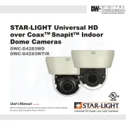
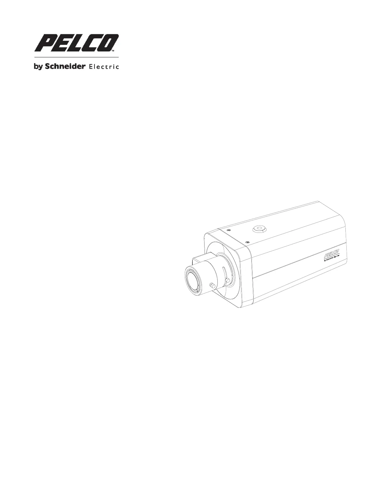
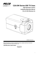
Model: | Sarix IXP31 |
Har du brug for hjælp?
Hvis du har brug for hjælp til Pelco Sarix IXP31 stil et spørgsmål nedenfor, og andre brugere vil svare dig
Overvågningskamera Pelco Manualer

21 August 2024

21 August 2024

21 August 2024

21 August 2024

21 August 2024

21 August 2024

21 August 2024

21 August 2024

20 August 2024

20 August 2024
Overvågningskamera Manualer
- Overvågningskamera Kogan
- Overvågningskamera Sitecom
- Overvågningskamera Yale
- Overvågningskamera Vimtag
- Overvågningskamera Iget
- Overvågningskamera Sentry360
- Overvågningskamera Minox
- Overvågningskamera V-TAC
- Overvågningskamera Tesla
- Overvågningskamera Vaddio
- Overvågningskamera EZVIZ
- Overvågningskamera Eminent
- Overvågningskamera Laserliner
- Overvågningskamera Creative
- Overvågningskamera Kerbl
Nyeste Overvågningskamera Manualer

31 Maj 2025

31 Maj 2025

7 April 2025

7 April 2025

6 April 2025

29 Marts 2025

28 Marts 2025

20 Marts 2025

20 Marts 2025

20 Marts 2025