Rane FME 15 Manual


Læs gratis den danske manual til Rane FME 15 (4 sider) i kategorien Ikke kategoriseret. Denne vejledning er vurderet som hjælpsom af 2 personer og har en gennemsnitlig bedømmelse på 4.6 stjerner ud af 1.5 anmeldelser. Har du et spørgsmål om Rane FME 15, eller vil du spørge andre brugere om produktet?

Side 1/4
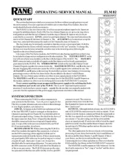
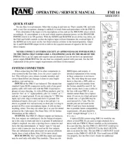
OPERATING / SERVICE MANUAL FME 15
EQUALIZER
QUICK START
For many of you, reading an owners manual is about as insulting as using training wheels
on your first two-wheeler. We therefore offer the following Quick Start section which outlines
the basics of the FME 15 so briefly it counts only as familiarization material, not training.
Using the FME 15 in an insert loop of a mixer is extremely easy. Simply connect them
together using a single stereo cable (¼" TRS) between the mixers insert loop and the FME
15s PATCH I/O jack. This jack is wired for the tip=send, ring=return convention used by
Anyone familiar with other graphic equalizers will find this one just as familiar. One word
of caution: the boost/cut RANGE switch drastically changes the impact of a given filter. Be
careful.
Set the IN and OUT GAIN controls to the same physical positions for unity gain through
the equalizer. That is, moving both slider handles together (keeping them aligned) always
maintains overall unity gain from input to output. Many strange gain structure conditions may
be handled with these controls. See the Operating Instructions on the back page for more
information. Most applications require only a few dB of boost or cut. Start with the RANGE
switch in the ±6dB position, and increase to ±12dB only if necessary. Setting curves is as easy
as it is on all Rane graphics thanks to our unique interpolating constant-Q circuitry. For more
information on setting up your curves correctly, again, see the back page.
NEVER CONNECT ANYTHING EXCEPT AN APPROVED RANE POWER SUP-
PLY TO THE RED THING THAT LOOKS LIKE A TELEPHONE JACK ON THE
REAR OF THE FME 15. This is an AC input and requires special attention if you do not have
an operational power supply EXACTLY like the one that was originally packed with your unit.
See the full explanation of the power supply requirements elsewhere in this manual.
SYSTEM CONNECTION
When first connecting the FME 15 to other components,
leave the power supply for last. This gives you a chance to
make mistakes and correct them without damaging your
fragile speakers, ears and nerves.
INPUTS. All three Inputs are wired in parallel and are
actively balanced (all Flex modules feature true instrumenta-
tion amplifier balanced inputs). Each works equally well.
Choose strictly from a favorite hardware point-of-view, there
will be no performance trade-offs. The wiring convention
adheres to American, British and International standards of
pin 2, +, or tip being hot; pin 3, “–”, or ring being return;
and pin 1, COMMON GND, or sleeve being signal ground.
Unbalanced operation involves using only pin 2, +, or tip as
signal; and pin 1, COMMON GND, or sleeve as ground. It is
not necessary to short any terminals or pins to any others. Due
to the true instrumentation nature of the inputs, there is no
gain reduction if pin 3, or “–”, is left open; however, if pin 3
gets shorted, it wont hurt anything either. Use pin 1, the
shell, or the COMMON GND point on the terminal strip for
shield ground. (See Rane Note 110 for further information).
OUTPUTS. The FME 15s Outputs mimic the Inputs.
True balanced output interconnection only requires the use of
pin 2, +, or tip; and pin 3, “–”, or ring for signal transmis-
sion. It does not require pin 1, or signal ground. All the signal
exists between the two balanced leads; ground is not in-
volved. Ground is used only for
shielding. If unbalanced output is
your preference, use pin 2, +, or
tip as signal; and pin 1, COMMON
GND, or sleeve as return. Leave
pin 3, “–, or ring open. Again,
have a look at Rane Note 110 for
more detail.
EXPANDING. Expanding and/
or daisychaining the inputs and outputs normally uses the ¼"
jacks. Multiple parallel connectors allow using another output
to drive a second processor or amplifier without special
cabling.
PATCH I/O. The PATCH I/O (Input/Output) jack makes
connection to mixer effects loop insert points very simple.
Just connect a shielded stereo tip-ring-sleeve (TRS) cable
between the FME 15s PATCH I/O jack and the TRS effects
loop insert on your console. (Your mixer must use the
tip=send, ring=return effects loop wiring convention.)
SIGNAL LEVELS. The FME 15 is designed for all line-
level signals. Signal levels from -10dBV to +4dBu or consid-
ered normal and within range (at least 16dB of headroom
exists above these levels). Do not directly connect micro-
phones into the FME 15. Use a mic preamp first.
FRONT PANEL DESCRIPTION
1. MASTER OVERLOAD INDICATOR. This red OL LED monitors the input,
output and all filter stages for excessive signal levels. It lights whenever these
levels exceed 4dB below clipping. Occasional flickering is normal; however, it
should not be allowed to light steadily.
2. OVERALL BYPASS SWITCH & INDICATOR. This pushbutton switch
activates the hard-wire bypass function. When pressed into the engaged
position (red BYPASS LED on), all three pins of the INPUT connectors are
directly connected to the same pins on the OUTPUT connectors (hard-wired).
Engaging this switch converts the FME 15 into a relatively expensive patch cord,
but one with pretty lights.
3. INPUT AND OUTPUT GAIN CONTROLS. These slide controls set the relative
IN and OUT gain structures. The range of each control is ±12dB; however, note
that they are labelled opposite to each other, i.e., the top of the IN control reads
+12dB while the top of the OUT controls reads -12dB. Configured this way,
whenever they are moved together to the same spots the overall gain through the
FME 15 stays at unity. Normally set these controls in their center detent positions.
4. FILTER LEVEL CONTROLS. These fifteen slide controls set the individual
levels of the interpolating constant-Q filters. Their range is selectable between
±6dB (use bottom or right-hand scale) and ±12dB (use top or left-hand scale). The
grounded center-detent design of these sliders ensures all filters are off when
positioned to their centers.
5. FILTER RANGE SWITCH. Sets the overall range of all sliders between ±6dB
and ±12dB.
6. POWER INDICATOR. This yellow LED lights any time remote power is
supplied from either a RS 1 or VC 18 single power supply or FRS 8 or RAP 10
multiple power supply (but not in the presence of Popes, Queens and Presidents as
one might well expect).


Produkt Specifikationer

Mærke: Rane
Kategori: Ikke kategoriseret
Model: FME 15

Har du brug for hjælp?

Hvis du har brug for hjælp til Rane FME 15 stil et spørgsmål nedenfor, og andre brugere vil svare dig


Ikke kategoriseret Rane Manualer
Rane

Rane AC 23B Manual

20 Juni 2025
Rane

Rane HM 42 Manual

20 Juni 2025
Rane

Rane SSE 22 Manual

20 Juni 2025
Rane

Rane TTM 54 Manual

20 Juni 2025
Rane

Rane SAC 22 Manual

20 Juni 2025
Rane

Rane SM26S Manual

20 Juni 2025
Rane

Rane AC 22 Manual

20 Juni 2025
Rane

Rane AC 23 Manual

20 Juni 2025
Rane

Rane FT 45 Manual

20 Juni 2025
Rane

Rane FME 15 Manual

20 Juni 2025

Ikke kategoriseret Manualer

Nyeste Ikke kategoriseret Manualer