Rane FMI 14 Manual
Rane
Ikke kategoriseret
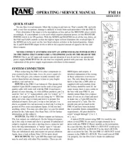
FMI 14

| Mærke: | Rane |
| Kategori: | Ikke kategoriseret |
| Model: | FMI 14 |
Har du brug for hjælp?
Hvis du har brug for hjælp til Rane FMI 14 stil et spørgsmål nedenfor, og andre brugere vil svare dig
Ikke kategoriseret Rane Manualer
22 Juni 2025
22 Juni 2025
21 Juni 2025
21 Juni 2025
21 Juni 2025
21 Juni 2025
21 Juni 2025
21 Juni 2025
21 Juni 2025
20 Juni 2025
Ikke kategoriseret Manualer
- Blaze
- Panasonic
- Eurolite
- Nanni
- Elinchrom
- Fulgor Milano
- KoolStar
- Proxxon
- Alpha Tools
- Topeak
- Weller
- Maxicool
- Peltor
- Robern
- SIME
Nyeste Ikke kategoriseret Manualer

17 December 2025

17 December 2025

17 December 2025

17 December 2025

17 December 2025

17 December 2025

17 December 2025

17 December 2025

17 December 2025

17 December 2025