Rane MLM 103 Manual


Læs gratis den danske manual til Rane MLM 103 (5 sider) i kategorien Ikke kategoriseret. Denne vejledning er vurderet som hjælpsom af 2 personer og har en gennemsnitlig bedømmelse på 4.9 stjerner ud af 1.5 anmeldelser. Har du et spørgsmål om Rane MLM 103, eller vil du spørge andre brugere om produktet?

Side 1/5
Manual-1
MLM 103
MIC/LINE MIXER
OPERATORS MANUAL
WEAR PARTS: This product contains no wear parts.
MLM 103 CONNECTION
INPUTS
The MLM 103 has ten balanced Euroblock Inputs. Use
only shielded cable. For best noise rejection use two-conduc-
Connect the non-inverting (positive) audio lines to the “+”
terminals, and the inverting (negative) lines to the “–”
terminals. Connect the shields to the “groundterminals.
For those installations where the MLM 103’s internal
shield-to-chassis connection causes interference, connect the
shields directly to chassis PEM nuts directly above each pair
of Euroblock connectors. Be sure to bite through the paint
with the star washer and keep the shields wrapped around the
audio conductors as much as possible. For the “theoretical”
best ElectroMagnetic Interference (EMI) immunity, connect
the shields at both ends of the cables. (For more information
on connections, see RaneNote 110, “Sound System Intercon-
nection” later in this manual or on Rane’s web site.)
MONO INPUTS 1-6 can accept either mic or line level
sources. When connecting line level signals, push the rear
panel button in for LINE. For mic signals, be sure the button
is in the MIC (out) position.
STEREO INPUTS 7/8 and 9/10 accept line level stereo
and mono sources.
OUTPUTS
The MLM 103’s OUTPUTS (and DIRECT OUTPUTS)
are balanced. The same wiring conventions as the Euroblock
Inputs apply.
QUICK START
If you don't get any further, at least read this section to get the best gain structure out of the MLM 103.
INPUTS 1 through 6 may be microphone or line level. The choice between the two is made by setting the Input’s LINE
push-button on the rear panel.
Push the PHANTOM POWER button (when needed) for each pair of Inputs.
Using a screwdriver, adjust the TRIM for each Input so that the front panel OL LED illuminates only occasionally
during extreme peaks. The three-band Equalizer settings will influence this, so keep an eye on the OL when making EQ
adjustments. Now adjust the LEVEL for each Input.
Assign each Input to the desired Output by pushing any combination of the A B, , or AUX ASSIGN buttons.
INPUTS 7/8 and 9/10 are stereo line level Inputs.
Assign each stereo input to the desired output as follows:
When the A/B ASSIGN button is engaged and the MONO button is not engaged, INPUT 7 (or 9) is routed to the A
Output, while INPUT 8 (or 10) is routed to the B Output.
When the both the A/B ASSIGN and MONO buttons are engaged, both Inputs of 7/8 (or 9/10) will route to both the A
and B Output.
The AUX ASSIGN button is always a mono mix of the stereo channel.
Manual-2
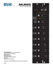
FRONT PANEL DESCRIPTION
Equalizer level controls are used to contour the frequency response of the desired Input.
Mic/Line OUTPUT ASSIGN buttons. When the A button is engaged, the Mic/Line Input’s audio is routed to Output A.
When the B button is engaged, the Mic/Line Input’s audio is routed to Output B. When the AUX button is engaged, the Mic/
Line Input’s audio is routed to the Aux Output. Any (or all) of the ASSIGN buttons can be engaged simultaneously.
Mic/Line INPUT LEVEL controls 1-6 determine the amount of signal to be delivered to the assigned Outputs.
Mic/Line OVERLOAD LED monitors the signal level before and after the Equalizer.
Stereo Line OUTPUT ASSIGN buttons. When the A/B assign button is engaged and the MONO button is not engaged,
Input 7 (or 9) is routed to the A Output, while Input 8 (or 10) is routed to the B Output. When both the A/B ASSIGN and
MONO buttons are engaged, both Inputs of 7 and 8 (or 9 and 10) will be routed to both the A and B Output. The AUX
ASSIGN button is a mono mix of the stereo Inputs.
Stereo Line INPUT LEVEL controls 7/8 and 9/10 determine the amount of stereo or mono line signal to be delivered to
the assigned Outputs.
Stereo Line OVERLOAD LED monitors the signal levels after the Equalizer and after the line gain stage.
Output Meters indicate the overall levels of Outputs A, B and the AUX Output. The Meters are “peak hold”.
A, B and AUX OUTPUT LEVEL controls set the Output Level for A, B and AUX Outputs.
POWER LED lights whenever adequate power is applied to the unit.


Produkt Specifikationer

Mærke: Rane
Kategori: Ikke kategoriseret
Model: MLM 103

Har du brug for hjælp?

Hvis du har brug for hjælp til Rane MLM 103 stil et spørgsmål nedenfor, og andre brugere vil svare dig


Ikke kategoriseret Rane Manualer

Rane

Rane AC 23B Manual

20 Juni 2025
Rane

Rane HM 42 Manual

20 Juni 2025
Rane

Rane SSE 22 Manual

20 Juni 2025
Rane

Rane TTM 54 Manual

20 Juni 2025
Rane

Rane SAC 22 Manual

20 Juni 2025
Rane

Rane SM26S Manual

20 Juni 2025
Rane

Rane AC 22 Manual

20 Juni 2025
Rane

Rane AC 23 Manual

20 Juni 2025
Rane

Rane FT 45 Manual

20 Juni 2025
Rane

Rane FME 15 Manual

20 Juni 2025

Ikke kategoriseret Manualer

Nyeste Ikke kategoriseret Manualer