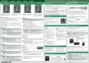
Controlling the parameters
Each eect unit lets you control the parameters by using the GRIFFER (GRF) knobs which allow
high-precision adjustment, and by inputting a CV/GATE signal.
The settings of the GRIFFER (GRF) knobs are added to the CV/GATE signal.
The indicator beside the knob changes its brightness according to the knob position and the
voltage of the CV/GATE signal.
This manual explains the factory-set parameters of the GRIFFER knobs and the buttons.
By using the dedicated software, you can reassign these to the desired parameters. (
* In the tables below, “B” indicates BITRAZER, “D” indicates DEMORA, “T” indicates TORCIDO,
and “S” indicates SCOOPER.
Model Indication Explanation
B SAMPLE RATE Lowers the sampling rate to create a noisy sound.
D TIME Adjusts the delay time.
T DIST Adjusts the depth of distortion.
Adjusts the amount of scatter.
“Scatter” adds a digital-feeling groove to the loop playback by
exchanging individual steps within the loop playback and also by
changing the playback direction or gate length.
Adjusts the amplitude of the CV signal (voltage) that is input to GRF 1.
* When the knob is minimized (turned fully left), the amplitude is 0.
Model Indication Explanation
B FILTER CUTOFF Adjusts the cuto frequency of the lter.
D FEEDBACK Adjusts the volume of the delay sound.
T TONE Adjusts the tonal character of the distortion.
S SCATTER TYPE Adjusts the type of scatter.
Adjusts the amplitude of the CV signal (voltage) that is input to GRF 2.
* When the knob is minimized (turned fully left), the amplitude is 0.
Model Indication Explanation
B BIT DOWN Lowers the bit depth to create a lo- sound.
Adjusts the volume of the pingpong delay sound (the delay heard
alternately from OUTPUT 1 and 2).
T TUBE WARM Produces a warm sound as if it were passing through a vacuum tube.
S PITCH Adjusts the pitch depth.
Model Indication Explanation
B RESONANCE Emphasizes the sound in the region of the cuto frequency.
D T DRY/WET Adjusts the balance of the dry sound and wet sound.
S FILTER Adjusts the eect of the lter.
Model Indication Explanation
B LPF/HPF Switches between a low pass lter and high pass lter.
D HOLD Continues holding the delay sound.
T LO BOOST Boosts the low-frequency sound.
Uses the GATE signal input to control the operation of the [REC/
[REC/PLAY] button (SCOOPER only)”
Model Indication Explanation
B D T BYPASS Bypasses the eect so that no eect is applied.
S SCATTER Turns the SCATTER eect on/o.
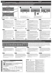
INPUT 1/2 jacks, OUTPUT 1/2 jacks
These are two monaural input/output jacks.
* To prevent malfunction and equipment failure, always turn down the volume, and turn
o all the units before making any connections.
“Using the Dedicated Software”)
Connect this to your tablet so that dedicated software settings can be input as audio signals.
When an audio signal is input to the [REMOTE IN] jack, the color or illumination of the center
indicator shows the reception status.
Center indicator during REMOTE input (common to all four models)
Indicator illumination Reception status
Blinking colorfully The audio signal is being input correctly.
Blinking alternately red and green
The audio signal is not being input correctly.
* If the center indicator does not change when you input an audio signal, or if a reception
error occurs, adjust the volume of the tablet and input the signal again.
Adjusts the output volume.
Lights when the power is on. The color and illumination indicates the status of this unit.
* For BITRAZER, DEMORA, and TORCIDO, this indicator is unlit when you turn BYPASS on.
For SCOOPER, this indicator is o if SCATTER is o and there is no recorded loop phrase.
[REC/PLAY] button (SCOOPER only)
If a GATE signal is not being input to the “GRF 5 SYNC TRIG,” recording (REC) or playback (PLAY)
starts the moment you press the button.
If a GATE signal is being input to the GRF 5 “SYNC TRIG,” recording (REC) or playback (PLAY)
start the moment a GATE signal is input after you press the button.
Connect a Eurorack power cable, or the included AC adaptor.
This turns the power on/o.
“Using the Dedicated Software”: “Using the dedicated software
Use a commercially available USB 2.0 cable (A-microB type) to connect your computer.
If this is connected, you’ll be able to edit the parameters of this eect unit from your
computer. You’ll also be able to use your computer to record and store the input from the
INPUT 1/2 jacks and CV/GATE jacks and the output to the OUTPUT 1/2 jacks.
* You must install the USB driver before connecting the eect processor to your computer.
Download the USB driver from the Roland website. For details, refer to Readme.htm which is
included in the download.
http://www.roland.com/support/
Before using this unit, carefully read leaet “USING THE UNIT SAFELY” . After reading, keep the
document(s) including those sections where it will be available for immediate reference.
Copyright © 2015 ROLAND CORPORATION
All rights reserved. No part of this publication may be reproduced in any form without the
written permission of ROLAND CORPORATION.
Using the Dedicated Software
Dedicated software lets you add a lter or LFO, or to assign the desired parameters to the
knobs and buttons by using your tablet or computer.
By assigning parameters that are dierent than the initial parameters, you can also use this
unit virtually as a dierent eect processor.
You can access and download dedicated software for your device from the following
locations. For details on the dedicated software, refer to the help that is included with the
Device Destination website
Android tablet Google Play
Roland website: http://www.roland.com/support/
Using the dedicated software on a tablet
Use a patch cable to connect this unit's REMOTE IN jack to your tablet's headphone jack.
Using the dedicated software on a computer
Use a separately sold USB 2.0 cable (A-microB type) to connect the USB port on the rear panel
of this unit to your computer.
* In order to connect this unit to your computer, you must install the USB driver.
Using a Eurorack Power Cable
In addition to an AC adaptor, the unit can also be operated on Eurorack system power (+12 V)
by using the included Eurorack power cable.
Insert the 16-pin connector of the Eurorack power cable into the Eurorack power
connector. When inserting the connector, align it with the groove.
If there is no groove, align the wire bearing the red mark with pin number 1.
Connect the other connector of the Eurorack power cable to the DC IN jack of this unit.
* The +12 V power of the unit draws 450 mA of current. Use a power supply that can
deliver this amount of current.
For more about Eurorack power supply units, refer to the Roland website. Here you can
nd the latest information about units that have been veried to be compatible.
http://www.roland.com/support/
* Always turn the Eurorack unit o and unplug the power cord before plugging
the Eurorack power cable.
* Do not touch the electrical terminals when attaching the Eurorack power cable.
Model BITRAZER DEMORA TORCIDO SCOOPER
Power Supply AC adaptor or Eurorack power
Current Draw 950 mA (AC adaptor), 450 mA (Eurorack power)
Dimensions 106.6 (W) × 128.4 (D) × 58.3 (H) mm 4-1/4 (W) x 5-1/16 (D) x 2-5/16 (H) inches
Weight 320 g (excluding AC adaptor)
AC adaptor, Owner’s Manual, Leaet USING THE UNIT SAFELY, Eurorack
installation screws (4 pcs.), Eurorack power cable
* In the interest of product improvement, the specications and/or appearance of this unit
are subject to change without prior notice.
Roland: BITRAZER/ DEMORA/ TORCIDO/ SCOOPER
Restoring the Factory Settings (Factory Reset)
You can return the knob and button
parameter assignments to their factory-set
(initial parameter) settings.
While holding down the [GRF 5] and [GRF
6] buttons, turn the power on.
The [GRF 5] button blinks.
Press the [GRF 5] button.
The [GRF 5] button and [GRF 6] button
Turn the power o and then on again.
The settings are initialized, and the unit
returns to the factory-set condition.
Recording / Stop / Playback / Delete (SCOOPER only)
SCOOPER plays the recorded audio input as a loop phrase, and adds an eect such as SCATTER.
SCOOPER can record one loop phrase of up to
* The recorded phrase disappears when you
Press the [REC/PLAY] button to start
* During recording, the [REC/PLAY] button
blinks, and the center indicator is lit red.
Press the [REC/PLAY] button once again
When recording stops, the recorded sound
* During playback, the [REC/PLAY] button
is lit, and the center indicator blinks
While the recorded sound is playing back,
press the [REC/PLAY] button.
* If there is input at the INPUT 1/2 jacks,
the output switches from the recorded
sound to the audio input.
While stopped, press the [REC/PLAY]
* If there is input at the INPUT 1/2 jacks,
the output switches from the audio
input to the recorded sound.
During playback or while stopped, hold
down the [REC/PLAY] button.
When the recorded sound is deleted, the
center indicator blinks yellow/red. Then the
SCATTER status is indicated (on: green, o:
* You can also delete by holding down
the [SYNC TRIG] button and pressing the
“BITRAZER” (bit crusher eect processor)
lowers the sampling rate and bit depth to
digitally roughen the sound, giving it a lo-
“DEMORA” (delay eect processor) layers a
time-delayed sound with the original sound,
“TORCIDO” (distortion eect processor)
intentionally distorts the audio input, creating
an intense and deeply distorted sound.
“SCOOPER” (looper and scatter eect
processor) records the audio input (phrase)
for several seconds and repeatedly plays it
back or slices it, transforming it into a dierent
To the [DC IN] jack, connect the AC adaptor or a Eurorack power supply cable. (&“Using
Observing the cautions listed below, turn on the rear panel [POWER] switch.
* This unit is equipped with a protection circuit. A brief interval (a few seconds) after turning
the unit on is required before it will operate normally.
* After you’ve made connections correctly, be sure to turn on the power in the order of
the eect processor rst, and then the connected system. Powering-on in the incorrect
order may cause malfunctions or damage. When turning the power o, power-o the
connected system rst, and then the eect processor.
* Before turning the unit on/o, always be sure to turn the volume down. Even with the
volume turned down, you might hear some sound when switching the unit on/o.
However, this is normal and does not indicate a malfunction.
CV stands for “Control Voltage,” an electrical signal (control voltage)
that modies the behavior of an analog synth or Eurorack module.
GATE is a trigger signal that controls the beginning and end of an
envelope or other control voltage.
* This unit can receive CV in the range of “-10 – +10 V.” Adjust your
output device to stay within this range that can be received. You
must input a gate voltage of “+3 V” or higher.
* Use patch cables with monaural mini-plugs to connect other
Installing in a Eurorack case
Use the included screws (4 pcs.) to attach the unit to your Eurorack case at the locations indicated.
Keep small items out of the reach of children
To prevent accidental ingestion of the parts listed below,
always keep them out of the reach of small children.
Included Parts: Eurorack installation screws