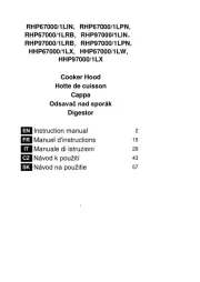
Rosieres RDR91/1BAV Manual
Læs gratis den danske manual til Rosieres RDR91/1BAV (24 sider) i kategorien Emhætte. Denne vejledning er vurderet som hjælpsom af 11 personer og har en gennemsnitlig bedømmelse på 3.8 stjerner ud af 6 anmeldelser.
Har du et spørgsmål om Rosieres RDR91/1BAV, eller vil du spørge andre brugere om produktet?

Produkt Specifikationer
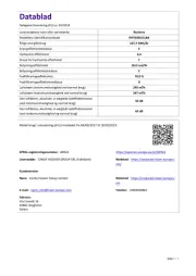
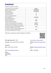
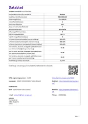
| Mærke: | Rosieres |
| Kategori: | Emhætte |
| Model: | RDR91/1BAV |
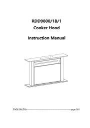
| Type: | Vægmonteret |
| Bredde: | 480 mm |
| Dybde: | 900 mm |
| Højde: | - mm |
| Produktfarve: | Hvid |
| Kontroltype: | Knapper |
| Antal hastigheder: | 3 |
| Motoreffekt: | 170 W |
| Lampetype: | Halogen |
| Støjniveau: | 65 dB |
| Pæreeffekt: | 40 W |
| Antal lyskilder: | 2 pære(r ) |
| Maksimal ekstraktionseffekt: | 440 m³/t |
| Udsugningsforbindelse, diameter: | 120 mm |
| Fedtfilter type: | Metal |
| Indbygget kapacitet: | Ja |
| Højde (min.): | 890 mm |
| Højde (maks.): | 1140 mm |
| Antal filtre: | 3 stk |
| Filter til opvaskemaskine: | Ja |
Har du brug for hjælp?
Hvis du har brug for hjælp til Rosieres RDR91/1BAV stil et spørgsmål nedenfor, og andre brugere vil svare dig
Emhætte Rosieres Manualer


Emhætte Manualer
- Whirlpool
- InAlto
- Faure
- Eurom
- Imperial
- Cookology
- Rommer
- Aspes
- Nodor
- Tisira
- Lamona
- Gemini
- Witt
- Schneider
- Saba
Nyeste Emhætte Manualer


