This device complies with part 15 of the FCC rules. Operation is subject
to the following two conditions: (1) this device may not cause harmful
interference, and (2) this device must accept any interference received,
including interference that may cause undesired operation.
NOTE: The grantee is not responsible for any changes or modifications
not expressly approved by the party responsible for compliance. Such
modifications could void the user’s authority to operate the equipment.
NOTE: This equipment has been tested and found to comply with the
limits for a Class B digital device, pursuant to part 15 of the FCC Rules.
These limits are designed to provide reasonable protection against harm-
ful interference in a residential installation. This equipment generates,
uses and can radiate radio frequency energy and, if not installed and used
in accordance with the instructions, may cause harmful interference to
radio communications. However, there is no guarantee that interference
will not occur in a particular installation. If this equipment does cause
harmful interference to radio or television reception, which can be deter-
mined by turning the equipment off and on, the user is encouraged to
try to correct the interference by one or more of the following measures:
Reorient or relocate the receiving antenna.
Increase the separation between the equipment and receiver.
Connect the equipment into an outlet on a circuit different from that
to which the receiver is connected.
Consult the dealer or an experienced radio/TV technician for help.
This device complies with Industry Canada license-exempt RSS
standard(s). Operation is subject to the following two conditions: (1) this
device may not cause interference, and (2) this device must accept any
interference, including interference that may cause undesired operation
Under Industry Canada regulations, this radio transmitter may only oper-
ate using an antenna of a type and maximum (or lesser) gain approved for
the transmitter by Industry Canada. To reduce potential radio interference
to other users, the antenna type and its gain should be so chosen that
the equivalent isotropically radiated power (e.i.r.p.) is not more than that
necessary for successful communication.
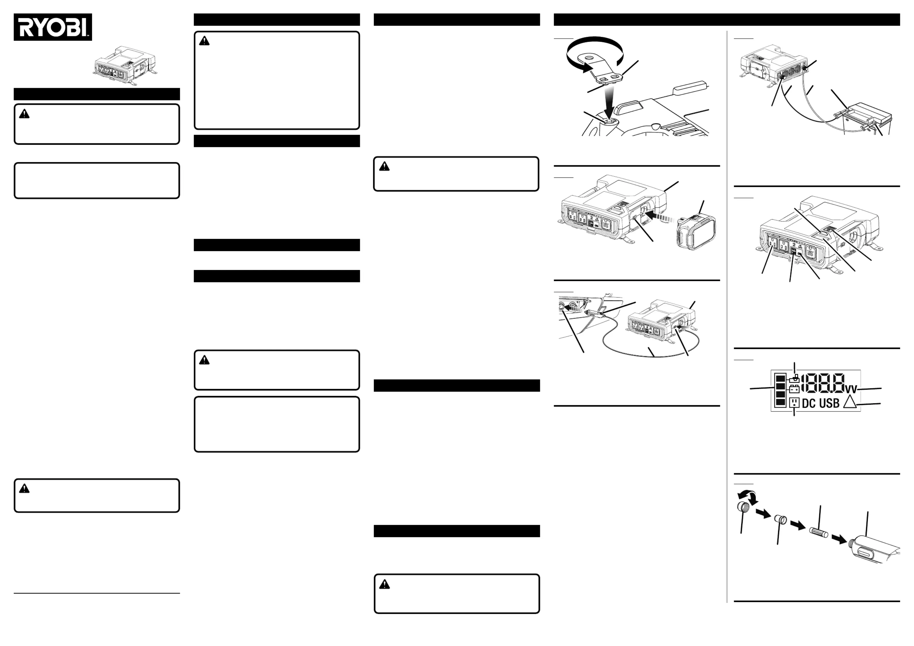
A - Fuse cover (capuchon du fusible, tapa de fusible)
B - Fuse cap (capuchon fusible, tapa ce la fusible)
C - 12 amp fuse (fusible de 12 A, fusible de 12amperios)
D - 12 volt DC plug (prise 12 V CC, enchufe de CC de 12 voltios)
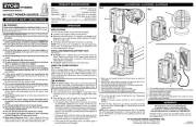
IMPORTANT SAFETY INSTRUCTIONS
READ AND UNDERSTAND ALL INSTRUCTIONS. Failure to follow
all instructions listed below may result in electric shock, fire, and/
SAVE THESE INSTRUCTIONS - This manual contains important
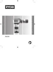
safety and operating instructions for inverter model RYi8030A.
This product’s AC receptacle has a non-sinusoidal output and is not
recommended for use with certain types of sensitive electronics.
Please refer to your product's operator’s manual.
Do not expose to rain or use in damp locations.
To reduce the risk of injury, close supervision is necessary when
an appliance is used near children.
Store inverters indoors and away from children.
As with all electrical devices, use caution when plugging and
unplugging this unit into an outlet or plugging/unplugging other
devices into this unit. Do not force this unit into an outlet. Do not
force plugs into this unit.
To reduce the risk of damage to electric plug and cord, pull by
plug rather than cord when disconnecting inverter.
Do not use inverter if it has been dropped or received a sharp
blow. A damaged inverter will increase the risk of fire.
If this unit is used in a manner not specified by the manufacturer,
the protection provided by this equipment may be impaired.
Do not overload the tool. It must be used for powering devices less
Operate this product using only the AC power type listed in the
Two- or three-prong plugs may be used with this product. Do
not force a polarized plug (one prong larger than the other) into this
product. Flip plug over and retry.
Never block air vents. Blocked vents may cause overheating. Inverter
will automatically shut off when overheated.
Keep inverter cool. Do not place near vehicle heat vents or in direct
Do not store appliance in locations where the temperature is less than
14° F or more than 104° F. Do not store outside or in vehicles.
Do not use appliance in locations where the temperature is less than
14° F or more than 104° F.
Use this product only with batteries and chargers listed in
tool/appliance/battery pack/charger correlation supplement
Use only with power cord provided.
Disconnect inverter from power supply when not in use.
Do not use the inverter around flammable fumes and gasses,
such as in the bilge of a boat or near propane tanks.
Do not use in an enclosed area with automotive lead acid
Do not put foreign objects into the inverter.
Refer to the operator’s manual for the vehicle or contact the
vehicle manufacturer for the proper 12V power receptacle.
To reduce the risk of fire, do not connect to an AC load center
(circuit breaker panel) having multiwire branch circuits connected.
Do not power life support devices, or other necessary medical
equipment with this tool.
This unit should never be hard wired into a circuit.
This unit should never be wired into a AC distribution circuit.
Do not attempt to set up, make adjustments or power devices
while operating a vehicle.
Save these instructions. Refer to them frequently and use them to
instruct others who may use this product. If you loan someone this
product, loan them these instructions also.
Risk of Fire. Do not replace any vehicle fuse with a rating higher
than recommended by the vehicle manufacturer. This product is
rated to draw 12 amperes from 13.8V vehicle outlets. Ensure that
the electrical system in your vehicle can supply this product without
causing the vehicle fusing to open. This can be determined by mak-
ing sure the fuse in the vehicle which protects the outlet is rated
higher than 12 amperes. Information on the vehicle fuse ratings
are typically found in the vehicle operator’s manual. If a vehicle
fuse opens repeatedly, do not keep replacing it. The cause of the
overload must be found. Fuses should not be patched up with tin
foil or wire as this may cause serious damage elsewhere in the
electrical circuit or cause fire.
Watts Continuous 800 Watts ...................................................................
................................................... 120 to 800 Watts
12V DC Adaptor Connection 120 Watts ..............................................
18V Battery Connection 300 Watts ......................................................
Direct to Battery Connection (Alligator Clamps) 800 Watts .................
................................................................................ 12 Volt DC
AC Output 120 Volts, 120W max. (12V DC plug); .................................
650W (30 min)/600W max. continuous (12V battery terminal)
USB-A Output 5V(2.4A) Shared DC ........................................................
.... 5V(3A), 9V(2A), 12V(1.5A), 15V(1.5A), 20V(1A) DC
................................................. Modified Sine Wave
RYi8030 Inverter, Alligator Clamps, 12V DC Adaptor Cable, Mounting
Brackets, Operator's Manual
You may use this product for the following purposes:
Operating and charging USB-powered devices
Supplying electrical power for operating compatible electrical devices
such as, but not limited to, lighting, appliances, tools, motor load,
small load switch mode power supply, and fans
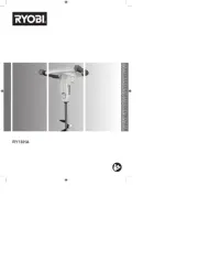
The power inverter converts low voltage DC electricity to 120V AC
household power allowing user to charge and power a variety of devices.
Risk of electric shock. When using a grounded appliance this tool
will not provide an electrical path to earth ground. Do not power
devices with damaged or frayed power cords.
Do not power this device with an outlet designated for lighting ciga-
rettes. If the 12V adaptor does not fit firmly into the auxiliary power
port, the receptacle is not suitable for use with the inverter. A poor
connection at the base of the 12V adaptor could lead to electrical
problems in the vehicle outside of the protections offered by the
vehicle or inverter’s fuse.
INSTALLING THE MOUNTING BRACKETS
The mounting brackets can be installed to provide a stable base for the
inverter. The unit can be used horizontally or mounted vertically.
CONNECTING TO AN 18V BATTERY
To install: With the power inverter off, place the battery in the installer
as shown. Make sure the battery pack is secured on the inverter before
To remove: Lift off the battery pack.
CONNECTING TO A 12V AUTO ACCESSORY
Using your vehicle’s 12V DC receptacle, the inverter will provide power
through the 120V AC outlets and/or USB ports.
NOTE: Some vehicles require the ignition to be turned on before power
is supplied to an accessory outlet.
With power inverter turned off, insert the connector cord plug into the
receptacle on the side of the inverter.
Plug the 12V DC plug into the 12V DC power port.
USING ALLIGATOR CLAMPS TO CONNECT TO
A set of alligator clamps is included with the inverter, one for the black
lead, and another for the red lead. When you want the inverter to remain
connected to the battery, but want to keep your hands free for other
operations, the alligator clamps will hold the leads in place.
NOTE: The inverter is compatible with 12V lead-acid, lithium-ion, and
deep-cycle gel batteries. The inverter will shut off automatically at 10.5V
as part of under voltage protection.
Make sure the inverter is turned off.
Connect the red cable to the positive (+) terminal first, then connect
the black cable to the negative (-) terminal. Make sure all connections
Connect the cables to the battery using the alligator clamps.
NOTE: Do not allow the inverter to hang by its leads when the clamps
are connected to the battery.
To avoid damaging the inverter or blowing the fuses, always remove
the test leads from the battery.
Press and hold the power button for three seconds to turn the inverter
ON. The LED will light up green when ready to use.
Plug devices you want to power or charge into the inverter’s USB
ports and/or 120 volt receptacle.
If the power button LED blinks red then turns off, the inverter may
be overloaded. Disconnect your device, make sure your battery
pack is sufficiently charged to power your device, then press the
button to turn the inverter back on. Reconnect your device and try
again. If the fault condition immediately reoccurs, the item being
powered exceeds the capacity of the inverter.
If the power button LED turns red but does not shut down the
inverter, the inverter is overheated. Allow the unit to cool until the
LED turns green, then try again.
If the power button LED flashes yellow, the battery pack needs to
Tap the power button one time to toggle between output power
(watts) and (volts) on the digital display.input power
To use the worklight, press the light button. Press the light button
again to turn the worklight off.
The inverter must be on for the worklight to function.NOTE:
When finished, disconnect your device and press the power button
indicator again for three seconds to turn off the inverter.
NOTE: When needed, an internal cooling fan will run to regulate the
unit’s operating temperature. If running, always wait for the fan to stop
before you disconnect the battery pack from the inverter.
Always replace the fuse with a 5D 12 Amp fast blow glass fuse. Never
replace the fuse with a higher-rated fuse.
Make sure LED power button/overload indicator is .OFF
Disconnect any USB or AC devices that are plugged into the inverter.
Unscrew fuse cover and remove from 12 V plug.
Remove the blown fuse. Replace with the new fuse.
Reinstall the fuse cap and fuse cover. Tighten securely.
The following replacement parts may be ordered by calling our customer
service department at 1-800-525-2579:
.................................................................... 870291007
......................................................... 290426042
......................................................... 290426041
................................................................. 638700062
This product has a Three-year Limited Warranty for personal, family, or
household use (90 days for business or commercialuse). For warranty
details, visit www.ryobitools.com orcall(tollfree) 1-800-525-2579.
Changes or modifications to this unit not expressly approved by the
party responsible for compliance could void the user’s authority to
ILLUSTRATIONS / ILLUSTRÉES / ILUSTRADAS
IMPORTANT SAFETY INSTRUCTIONS OPERATION
A - Power inverter (inverseur de courant, inversor de corriente)
B - 12V DC plug (prise de 12 V CC, enchufe de CC de 12 V)
C - 12V DC power port (port CC de 12 V, puerto de CC de 12 V)
D - Connector cord plug (connecteur, enchufe del cable del conector)
E - Receptacle (prise, receptáculo)
TTI OUTDOOR POWER EQUIPMENT, INC.
P.O. Box 1288, Anderson, SC 29622, USA
1-800-525-2579 www.ryobitools.com
A - Power inverter (inverseur de courant, inversor de corriente)
B - 18V battery (pile de 18 V, batería de 18 V)
C - Connector cord plug (connecteur, enchufe del cable del conector)
A - LED power button/overload indicator (témoin DEL/indicator de surcharge, botón
LED de encendido//indicador de sobrecarga )
B - 120 V receptacle (réceptacle 120 V, receptáculo de 120 voltios)
C - USB-A port (port USB-A, puerto USB-A)
D - 2.4A USB-C port (port USB-C 2,4A, puerto USB-C de 2,4 A)
E - LCD display (écran ACL, pantalla LCD)
F - LED light (lampe à DEL, luz LED)
A - Black cable (–) [cable noir (–), cable negro (–)]
B - Red cable (+) [cable rouge (+), cable rojo(+)]
C - Alligator clamps (pinces crocodiles, pinzas de contacto)
D - Negative (–) terminal [borne négative (–), terminal negativa (–)]
E - Positive (+) terminal [borne positive (+), tapa del terminal positiva(+)]
A - Battery level (niveau de la pile, nivel de la batería)
B - Battery type (types de pile, tipo de batería)
C - AC power (alimentation CA, alimentación de CA)
E - Input voltage “V” and output wattage “W” (tension d’entrée « V » et puissance de
sortie « W », voltaje de entrada “V” y potencia de salida “W”)
A - Mounting bracket (support de fixation, soporte de montaje)
B - Tabs (languettes, lengüetas)