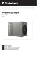
Samsung AE160MXTPGH Manual
Samsung
Varmepumpe
AE160MXTPGH
Læs nedenfor 📖 manual på dansk for Samsung AE160MXTPGH (52 sider) i kategorien Varmepumpe. Denne guide var nyttig for 6 personer og blev bedømt med 4.3 stjerner i gennemsnit af 3.5 brugere
Side 1/52

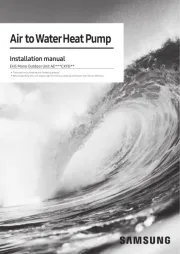
Air to Water Heat Pump -Air to Air Heat pump
Installation manual
AE044MXTPEH/AE066MXTPEH/AE090MXTPEH/AE120MXTPEH/
AE160MXTPEH/AE090MXTPGH/AE120MXTPGH/AE160MXTPGH
• Thank you for purchasing this Samsung air conditioner.
• Before operating this unit, please read this manual carefully and retain it for future
reference.

2English
Contents
PREPARATION 3
Safety Precautions 3
Product Specification 6
INSTALLATION 9
Locating the Units 9
Installing the Refrigerant Pipe Work 15
Electrical Connections 29
Setting the Option Switch and Function of the Keys 36
Setting key function 39
Pump down procedure 42
Completing the Installation 45
Final Checks and Trial Operation 46
OTHERS 47
Troubleshooting 47
Optional : Extending the power cable 49
Reference (HP KEYMARK Certification) 51
Correct Disposal of This Product
(Waste Electrical & Electronic Equipment)
(Applicable in countries with separate collection systems)
This marking on the product, accessories or literature indicates that the product and its electronic accessories
(e.g. charger, headset, USB cable) should not be disposed of with other household waste at the end of their
working life. To prevent possible harm to the environment or human health from uncontrolled waste disposal,
please separate these items from other types of waste and recycle them responsibly to promote the sustainable
reuse of material resources.
Household users should contact either the retailer where they purchased this product, or their local government
office, for details of where and how they can take these items for environmentally safe recycling.
Business users should contact their supplier and check the terms and conditions of the purchase contract. This
product and its electronic accessories should not be mixed with other commercial wastes for disposal.
For information on Samsung’s environmental commitments and product-specific regulatory obligations, e.g. REACH,
visit: www.samsung.com/uk/aboutsamsung/sustainability/environment/our-commitment/data/

3
English
PREPARATION
• You must install the product by qualified installer. If
you install the product on your own or by unqualified
person, Samsung is not responsible for any damages
which may occur due to incorrect installation.
• Make sure to read the following safety precautions
carefully before installation.
• Make sure to observe the cautions specified in this
manual.
• Conduct a test run of the unit after installation and
then explain all system functions to the owner.
• Follow IEC (International Electrotechnical Commission)
standards for the power input and ISO (International
Standards Organization) standards for input current.
• R410A refrigerant is used for Air to Water Heat pump.
– When using R410A, moisture or foreign substances
may affect to the capacity and reliability of the
product. Safety precautions must be taken when
installing the refrigerant pipe.
– The design pressure of the unit is 4.1 MPa
(41.8 kgf/cm²). Select appropriate material and
thickness according to the regulations.
– R410A is a quasi-azeotrope of two refrigerants.
Make sure to charge liquid one when adding
refrigerant. If you charge gaseous refrigerant,
it may affect the capacity and reliability of the
product as a result of change formation of the
refrigerant.
• Connect only the indoor units fit on R410A refrigerant.
Check whether the indoor units can be connected with
the product’s catalogue. (When incorrect indoor units
are connected, they cannot operate normally.)
• When installing, use tools and materials for R410A
only. If you use tools and materials for R22, there is
potential risk of bursting, injury, electric shock and
fire because the pressure of R410A is higher than the
pressure of R22(conventional).
WARNING
• Hazards or unsafe practices that may result in
severe personal injury or death.
• Installation must be carried out by a qualified installer.
Do not attempt to repair, move, modify or reinstall the
unit on your own since such act may cause fire, electric
shock or water leakage.
• Install the unit in a place where it is strong enough
to hold the product weight. When installed in place
where it is not strong enough to withhold the product
weight, the unit could fall and cause injury.
• The unit should be installed in accordance with the
National Electrical regulations. Check if the voltage
and the frequency of the main power supply are
those required for the unit to be installed and check
the connection. Do not share the power outlet with
other appliances. Incomplete connection, defective
insulation or exceeding the permissible current may
cause electric shock or fire.
• Use the specified wires to connect the indoor and
outdoor units securely and attach the wires firmly to
the terminal block connecting sections so that the
pressure is not applied to the sections. Inappropriate
connection and fixing could cause fire.
• Attach the electrical cover to the indoor and outdoor
unit securely without any gaps. If there are any gaps,
there is potential risk of fire or electric shock due to
dust or water.
• Make sure to use the part provided or specified parts
for the installation work. The use of defective parts
could cause an injury or leakage of water due to a fire,
an electric shock, the unit falling, etc.
• Make sure that the refrigerant gas does not leak after
completing the installation. If the refrigerant gas of
the indoor unit leaks and comes into contact with the
fan heater, space heater or stove, harmful gas will be
generated.
• Ensure that the national safety code requirements
have been followed for the main supply circuit. Ensure
that a proper ground wire is in place. Do not connect
the ground to a gas pipe, water pipe, lightning rod or
telephone grounding. Defective grounding could cause
electric shock.
Safety Precautions

4
Safety Precautions
English
PREPARATION
• Do not install the unit in a place with direct sunlight,
dangerous substances or where it is exposed to
inflammable gas leakage to prevent explosion, fire or
personal injury.
• Perform the installation securely referring to the
installation manual. Incomplete installation could
cause personal injury due to fire, electric shock and
water leakage or from the unit falling.
• Check first the following situations before starting the
operation during the installation.
– The pipe must be properly connected and make
sure there is no leakage.
– Service valves must be open. If compressor is
operated with the service valve closed, excessive
pressure may damage parts of the compressor. If
leakage occurs on any of the connection, air inflow
may also cause excessive pressure that could lead
to explosion.
• Stop the compressor before disconnecting the
refrigerant pipe for pump-down operation. If you
disconnect the refrigerant pipe while compressor is
operating with service valve open, air inflow will cause
excessive pressure in the refrigerant cycle that could
lead to explosion and personal injury.
• Be sure not to perform power cable modification,
extension wiring, and multiple wire connection.
– It may cause electric shock or fire due to poor
connection, poor insulation, or current limit
override.
– When extension wiring is required due to power
line damage, refer to "How to connect your
extended power cables" in the installation manual.
• Make sure to turn off the main power when setting up
the indoor unit electrical circuit or power cords. There
is a risk of electric shock.
• Make sure that proper circuit breaker and safety
switches are installed. Install a ground leakage
breaker depending on the installation place (where it
is humid). If not, it may cause electric shock.
• Do not install the unit by yourself (owners). Incorrect
installation of the unit could cause injury due to fire,
electric shock and water leakage or from the unit
falling. Consult a dealer or a qualified installer.
• Use the unit on a single outlet circuit. Do not share the
power outlet with other appliances. Obtain the consent
by a qualified installer before connecting the unit to
the power supply system. An all pole disconnection
from the power supply must be incorporated in the
fixed wiring with a contact opening of >3mm.
• Manufacturer is not responsible for accidents due to
incorrect installation.
• When you install the Air to water heat pump in a small
room, you consider a proper ventilation to prevent a
leakage level within the maximum permissible limit.
– In that case, you may die from suffocation by some
possibility.
• Fix the outdoor unit securely to prepare against strong
wind or earthquake.
– If the outdoor unit is not properly fixed, it turns over
and accidents may occur.
• If any gas or impurities except R410A refrigerant come
into the refrigerant pipe, serious problem may occur
and it may cause injury.
• Install the cables with supplied cables firmly. Fix them
securely so that external force is not exerted to the
terminal board.
– If the connection or fixing is incomplete, it can
cause trouble with a heat generation, electric shock
or fire and so on.
• Wear protective equipment (such as safety gloves,
goggles, and headgear) during installation and
maintenance works. Installation/repair technicians
may be injured if protective equipment is not properly
equipped.
• This appliance is not intended for use by
persons(including children) with reduced physical,
sensory or mental capabilities, or lack of experience
and knowledge, unless they have been given
supervision or instruction concerning use of the
appliance by a person responsible for their safety ;
Young children should be supervised to ensure that
they do not play with the appliance.
• For use in Europe : This appliance can be used by
children aged from 8 years and above and persons
with reduced physical,sensory or mental capabilities
or lack of experience and knowledge if they have been
given supervision or instruction concerning use of the
appliance in a safe way and understand the hazards
involved. Children shall not play with the appliance.
Cleaning and user maintenance shall not be made by
children without supervision.

5
English
PREPARATION
CAUTION
• Hazards or unsafe practices that may result in
minor personal injury or property damage.
• Perform the drainage/piping work securely according
to the installation manual. If not, water could drop
from the unit and household goods could get wet and
damaged.
• Fasten a flare nut with a torque wrench as specified
in this installation manual. When fastened too tight,
a flare nut may break after a long period of time and
cause refrigerant leakage.
• Wear thick gloves during the installation process. If
not, personal injury may occur due to the Air to water
heat pump parts.
• Be careful not to touch the outdoor unit inlet or
aluminum pins. You may get personal injury.
• Do not install the outdoor unit in a place where
animals could live. If an animal get contact with the
electric parts, damage or fire may occur. In addition
ask the customer to maintain a clean installation place
around it.
• After completing the installation run the trial
operation. If no error occurs, explain to the customer
how to use and clean the Air to water heat pump
according to the user’s manual. In addition give the
installation manual and the user’s manual to the
customer.
• Check the unit for damage that may have taken
place during transportation and do not install or use
damaged equipment.
• All of the manufacturing and packaging material
used for your new appliance are compatible with the
environment and can be recycled.
• Dispose of the packaging material in accordance with
the local requirements.
• This product is an air conditioning system and contains
a coolant that must be recovered and disposed of
in an appropriate way by qualified personnel. At the
end of the life cycle, take it to a proper recycling or
disposal center or return it to the dealer so that it can
be disposed correctly.
• Do not connect the heater to the outdoor unit
and do not install remodeled duct as you please.
‐The capacity of the Air to water heat pump
may reduce, electric shock or fire may occur
and it has a chance of occurrence of and
accident like electric shock or fire.
• Make sure that the condensed water dripping
from the drain hose runs out properly and
insulate the drain pipe so that frost does not
generate.
‐Household goods may get wet if the drain
pipe is not properly installed.
• Install the power cable and communication cable
of the indoor and outdoor unit at least 1.5m away
from electric appliances.
‐Noise may hear depending on the electric
wave though the cables are installed away
from electric appliances.
• Install the indoor unit away from lighting
apparatus using the ballast.
‐If you use the wireless Remote controller, it may
not operate normally.

6
Product Specification
English
PREPARATION
Product Specification
Shape of the outdoor unit
Model
Name
AE044MXTPEH
AE066MXTPEH
AE090MXTPEH
AE090MXTPGH
AE120MXTPEH
AE160MXTPEH
AE120MXTPGH
AE160MXTPGH
Shape
Outdoor Weight(net)
(kg)
Dimensions (net)
(mm)
AE044MXTPEH 61 880 x 793 x 310
AE066MXTPEH 61 880 x 793 x 310
AE090MXTPEH 74 940 x 998 x 330
AE090MXTPGH 76 940 x 998 x 330
AE120MXTPEH
AE120MXTPGH
AE160MXTPEH
AE160MXTPGH
107 940 x 1,420 x 330
Accessories
• Keep supplied accessories until the installation is
finished.
• Hand the installation manual over to the customer
after finishing installation.
• The quantities are indicated in parentheses.
Installation manual (1) Rubber-leg (4)
Drain plug
AE044/066∗
AE090/120/160∗
1 2
Drain cap
AE044/066∗
AE090/120/160∗
3 5

7
English
PREPARATION
Product compatibility
Indoor unit
Outdoor unit
Slim Duct MSP Duct RAC Console Hydro Unit
Tank
Integrated
Hydro Units
2.2~5.6kW 3.6~9kW 2.2~5.6kW 9/16kW 200~260L2.2~7.1kW
Classification Features
AE022MNLDEH
AE028MNLDEH
AE036MNLDEH
AE056MNLDEH
AE022ANLDEH
AE028ANLDEH
AE036ANLDEH
AE056ANLDEH
AE071MNMPEH
AE090MNMPEH
AE071ANMPEH
AE090ANMPEH
AE036BNMPEH
AE056BNMPEH
AE022TNXDEH
AE028TNXDEH
AE036TNXDEH
AE056TNXDEH
AE071TNXDEH
AE022MNJDEH
AE028MNJDEH
AE036MNJDEH
AE056MNJDEH
AE090MNYDEH
AE160MNYDEH
AE090MNYDGH
AE160MNYDGH
AE090BNYDEH
AE090BNYDGH
AE160BNYDEH
AE160BNYDGH
AE200TNWTEH
AE260TNWTEH
- Heat pump for
heating and hot
water system
[Eco Heating Full
System]
- Outdoor unit:
4.4/6.6/9/12/16
kW
- Long pipe
reliability: 75m
NOTE
• AE∗∗∗MXTP∗H and above EHS TDM Indoor units are applicable for EHS products only.
They are not compatible with EHS Split Hydro unit, CAC, DVM and FJM products.
• A2W: Air to Water, A2A: Air to Air

8
Product Specification
English
PREPARATION
Subsidiary materials compatibility
Indoor unit
Subsidiary materials
Slim Duct MSP Duct RAC Console Hydro Unit
Tank
Integrated
Hydro Units
Remark
2.2~5.6kW 3.6~9kW 2.2~5.6kW 9/16kW 200~260L2.2~7.1kW
EEV Kit
EEV Kit for 1/2/3
room
- -
MEV-E24SA
MEV-E32SA
MXD-E24K132A
MXD-E24K200A
MXD-E24K232A
MXD-E24K300A
MXD-E32K200A
MXD-E32K224A
MXD-E32K300A
- - - Requisite
Y-joint MXJ-YA1509M
(≤15.0kW and below) Requisite
Drain
Pump
AE**AN**:
MDP-Z075SZCD
(Option, Internal Type)
AE**MN**:
MDP-E075SEE3D
(Option, Internal Type)
MDP-G075SP
(Option, External
Type)
MDP-G075SQ
(Option, Internal
Type)
- - - -
Wireless
remote
controller
MR-EH00
(Option)
AR-EH03E
(Included)
MR-EH00
(Included) - -
Remote
controller
receive kit
MRK-A10N
(Option) - - - -
Wired
remote
controller
MWR-WE10N
(Option) - - MWR-WW00N
(Included) -
Wired
remote
controller
- - - - MWR-WW10N
(Option)
NOTE
• Subsidiary materials are compatible with DVM products.
• EEV KIT : Required installation. It is not included inside of product. Install distribution kit for 1, 2 or 3 indoor
on the ceiling or outdoor area.
• A2W: Air to Water, A2A: Air to Air

9
English
INSTALLATION
Locating the Units
Deciding on Where to Install the Outdoor
Unit
Decide the installation location regarding the following
condition and obtain the user’s approval.
• The outdoor unit must not be placed on its side or
upside down, as the compressor lubrication oil will run
into the cooling circuit and seriously damage the unit.
• Choose a location that is dry and sunny, but not
exposed to direct sunlight or strong winds.
• Do not block any passageways or thoroughfares.
• Choose a location where the noise of the Air to water
heat pump when running and the discharged air do
not disturb any neighbours.
• Choose a position that enables the pipes and cables to
be easily connected to the indoor unit.
• Install the outdoor unit on a flat, stable surface that
can support its weight and does not generate any
unnecessary noise and vibration.
• Position the outdoor unit so that the air flow is directed
towards the open area.
• Place the outdoor unit where there are no plants
and animals because they may cause malfunction of
outdoor unit.
• Maintain sufficient clearance around the outdoor unit,
especially from a radio, computer, stereo system, etc.
• Installation Guide at the seashore
Make sure to follow below guides when installing at
the seashore.
1. Do not install the product in a place where it is
directly exposed to sea water and sea breeze.
- Make sure to install the product behind a structure
(such as building) that can block see breeze.
- Even when it is inevitable to install the product
in seashore, make sure that product is not directly
exposed to sea breeze by installing a protection wall.
2. Consider that the salinity particles clinging to the
external panels should be sufficiently washed out.
3. Because the residual water at the bottom of the
outdoor unit significantly promotes corrosion, make
sure that the slope does not disturb drainage.
- Keep the floor level so that rain does not
accumulate.
- Be careful not to block the drain hole due to foreign
substance.
4. When product is installed in seashore, periodically
clean it with water to remove attached salinity.
5. Make sure to install the product in a place that
provides smooth water drainage.
Especially, ensure that the base part has good
drainage.
6. If the product is damaged during the installation or
maintenance, make sure to repair it.
7. Check the condition of the product periodically.
- Check the installation site every 3 months and
perform anti-corrosion treatment such as R-Pro
supplied by SAMSUNG (Code : MOK-220SA) or
commercial water repellent grease and wax, etc.,
based on the product condition.
- When the product is to be shut down for a
long period of time, such as off-peak hours, take
appropriate measures like covering the product.
8. If the product installed within 500m of seashore,
special anti-corrosion treatment is required.
※ Please contact your local SAMSUNG representative
for further details.
Sea
Sea breeze
Outdoor
unit
Outdoor
unit
Sea
Sea breeze
Outdoor
unit
Sea
Sea breeze
Outdoor
unit
Protection wall
Protection wall should be constructed with a solid material
that can block the sea breeze and the height and width of the
wall should be 1.5 times larger than the size of the outdoor
unit.(You must secure more than 700 mm of space between
the protection wall and the outdoor unit for air circulation.)
• Do not install the Air to Water Heat pump in following
places.
– The place where there is mineral oil or arsenic acid.
There is a chance that parts may get damaged due
to burned resin.
The capacity of the heat exchanger may reduce or
the Air to Water Heat pump may be out of order.
– The place where corrosive gas such as sulfurous
acid gas generates from the vent pipe or air outlet
The copper pipe or connection pipe may corrode
and refrigerant may leak.
– The place where there is a danger of existing
combustible gas, carbon fiber or flammable dust.
The place where thinner or gasoline is handled.

10
Locating the Units
English
INSTALLATION
CAUTION
• Do not install the outdoor unit in a snowy and
cold area (low temperature and high humidity
area - where the temperature is below -7 °C
and humidity is higher than 85%) because
according to operation condition (defrost, etc.),
ice may be formed in the drain route. If the ice is
accumulated, it may cause critical damage to the
product. (ex) lakeside of cold area in winter time,
seashore, alpine region and etc.)
• You have just purchased Air to Water Heat pump
and it has been installed by your installation
specialist.
• This device must be installed according to the
national electrical rules.
• With an outdoor unit having net weight
upper than 60kg, we suggest do not install
it suspended on wall, but considering floor
standing one.
• Avoid a place that may disturb your neighbor. Noise
may occur from the outdoor unit and the discharged
air may run into the neighborhood. (Be careful of the
operation time in a residential area.)
• Install the outdoor unit on a hard and even area that
can support its weight.
• Choose a flat place that rainwater does not settle or
leak.
• Choose a place avoiding strong winds.
• Maintain sufficient space for repairs and service.
• Choose a place where you can easily connect the pipes
and cables to the indoor unit.
• Make sure that the condensed water dripping from the
drain hose runs out properly and safely.
• If you install the outdoor unit by the sea or a spa,
concern about corrosion.
• Build a support where may have a heavy snow so that
the air intake is not blocked by snow.
• Install a protective safety fence to eliminate the
possibility of falling.
Space Requirements for Outdoor Unit
• Observe the clearances and dimensions as seen below
when installing the outdoor unit.
• If you install several outdoor units simultaneously,
observe the space for ventilation and free airflow.
If the space for ventilation is insufficient, the Air to
water heat pump may be inefficient.
• SAMSUNG logo is attached on the front side of the
outdoor unit.
Figure Description
Top view Side view
Back side: Air intake
Front side: Air outlet
Front side:
Air outlet
Back side:
Air intake
• , Air flow direction.

11
English
INSTALLATION
When installing 1 outdoor unit
(Unit: mm)
When the air outlet is opposite
the wall
When the air outlet is toward
the wall
300 or more
1500 or more
When 3 sides of the outdoor
unit are blocked by the wall
The upper part of the outdoor
unit and the air outlet is
toward the wall
300 or more
150 or more 600 or more
1500 or more
2000 or more
The upper part of the outdoor
unit and the air outlet is
opposite the wall
When the walls are blocking
front and the rear side of the
outdoor unit
500 or more
300 or more
1500 or
more
300 or
more
When installing more than 1 outdoor unit
(Unit: mm)
When the air outlet is toward the wall
1500 or more
600 or more
600 or more
When 3 sides of the outdoor unit are blocked by the wall
300 or more
300 or more 600 or more 600 or more 600 or more
When the walls are blocking front and the rear side of the
outdoor units
300 or
more
1500 or
more
600 or more600 or more
When front and rear side of the outdoor unit is toward the wall
1500 or
more
600 or
more
3000 or more 300 or
more
3000 or more

13
English
INSTALLATION
Disassembling the Leg Base and Wood
Palette / Fastening the Anchor Bolt
1 Disassemble the three screws (with an electric
driver) which fixes wood palette.
2 Disassemble the bottom-left screw with monkey
spanner.
• Do not remove guard fan.
Wood palette
Monkey spanner
3 After removing the wood palette, move the outdoor
unit to the installation place.
4 Fasten the bottom-left screw with monkey spanner
first, and then fasten the other three anchor bolts.
Screw
Installing the Outdoor Unit
CAUTION
• Do not install the outdoor unit on a wooden
pallet palette.
• Fix the outdoor unit completely to the base fix
the outdoor unit with anchor bolts.
• The manufacturer is not responsible for the
damage occurred by not keeping standard of the
installation.
• Install the outdoor unit higher than 150mm from the
base surface and install the drain hole to connect the
pipe to the drainage.
• If front fan outdoor unit is installed where average
snow fall is 150mm or more, a duct should be fitted to
the unit.
• The concrete foundation should be 1.5 times larger
than bottom of the outdoor unit.
• When heating, condensed water may be generated.
Pay attention to waterproof and drainage of the
concrete foundation where the outdoor unit is
installed. (An ice patch may form on the base surface
in winter.)
• Install a square pad(t=20mm or more) to prevent
vibration of the outdoor unit delivering to the base
surface when installing the concrete for the outdoor
unit.
※ Base mount construction
(Unit : mm)
< When installing on the ground >
Drain hole
150 or more
< When installing on the roof >
Install the outdoor unit
horizontally on the ground
150 or more

15
English
INSTALLATION
Installing the Refrigerant Pipe Work
• Install the refrigerant pipe within the maximum allowable length, difference in height and length of after the first
branch pipe.
• The pressure of the R410A is high.
Use only rated refrigerant pipe and follow the installation method.
• Use clean refrigerant pipe Where there is no harmful ion, oxide, dust, iron content or moisture.
• Use adequate tools and accessories for R410A.
Manifold gauge • Use manifold gauge only for R410A to prevent the inflow of foreign substances.
Vacuum pump
• Use vacuum pump with check valve to prevent pump oil from flowing backward while
the vacuum pump is stopped.
• Use the vacuum pump that the vacuum induction is available up to 5 Torr (666.6Pa ,
0.0067 kgf/cm², 5 mmHg)
Flare nut • Use only flare nut supplied with the product.
Allowable Length of the Refrigerant Pipe and the Installation Examples
AE044MXTPEH/AE066MXTPEH
Outdoor unit Indoor unit
Y-Joint
EEV kit
Hydro unit
Item
Example Remarks
Maximum
allowable
length of pipe
Outdoor unit
~ Indoor units
Longest piping length
Less than 30m a+b+c+g ≤ 30m
Equivalent length
Less than 40m Y-joint and EEV kit : 0.5m
Total length
Less than 75m a+b+c+d+e+f+g ≤ 75 m 5m ≤ Total length ≤ 75m
Maximum
allowable
height
Outdoor unit
~ Indoor units Less than 20m
H1 If outdoor unit is located
lower position H1 ≤15m
Indoor unit ~
Indoor unit
Height difference
between indoor units
Less than 7.5m H2
Maximum
allowable
length of pipe
First Y-joint
~ Last indoor
unit
Actual piping
length
Less than 20m b+c+g ≤ 20 m (between first Y-joint and indoor unit)
h ≤ 20 m (between EEV kit and indoor unit)
Additional refrigerant
calculation
R=Basic Charge + Additional charge by the piping length + Additional charge by (A2A)Indoor
Basic Charge : Up to 10m When Installing A2W only = 2600g
Additional charge by the piping length : 3/8" - 50g/m, 1/4" - 20g/m
Additional charge by (A2A)Indoor unit : Refer to the 16 page 'Amount of additional refrigerant for each indoor unit'
table.

17
English
INSTALLATION
AE120/160MXTP∗H
Using only Y-joint Using EEV kit
Outdoor unit Outdoor unit
EEV
kit
Item
Example Remarks
Maximum
allowable
length of pipe
Outdoor unit
~ Indoor units
Longest piping length
Less than 70m a+b+c+d+e ≤ 70m
Equivalent length
Less than 85m Y-joint and EEV kit : 0.5m
Total length
Less than 200m
a+b+c+d+e+f+g+h+i ≤ 200m
10m ≤ Total length ≤ 200m
Maximum
allowable
height
Outdoor unit
~ Indoor units Less than 30m
H1 If outdoor unit is located
lower position H1 ≤ 25m
Indoor unit ~
Indoor unit
Height difference
between indoor units
Less than
15m
H2
Maximum
allowable
length of pipe
First Y-joint
~ Last indoor
unit
Actual piping
length
Less than 40m
b+c+d+e ≤ 40m (between first Y-joint and indoor unit)
h≤20m(between EEV kit and indoor unit)
Additional refrigerant
calculation
R=Basic Charge + Additional charge by the piping length + Additional charge by (A2A)Indoor
Basic Charge : Up to 10m When Installing A2W only = 3500g
Additional charge by the piping length : 3/8" - 50g/m, 1/4" - 20g/m
Additional charge by (A2A)Indoor : Refer to the 16 page 'Amount of additional refrigerant for each indoor unit' table.
• Contact the manufacturer if the length should exceed.
EEV Kit Model name Remarks
EEV Kit ~
Indoor units Actual pipe lengh
2m or less MEV-E24SA 1 indoor
Apply to products without EEV
(Wall mounted & ceiling)
MEV-E32SA
20m or less
MXD-E24K132A
2 indoorMXD-E24K200A
MXD-E32K200A
MXD-E24K232A
3 indoor
MXD-E24K300A
MXD-E32K224A
MXD-E32K300A
• Please refer to the EEV Kit manual.

18
Installing the Refrigerant Pipe Work
English
INSTALLATION
Selecting the Refrigerant Pipe
Installing pipes between outdoor unit and first
Y-joint
Model Liquid side Gas side (Air) Gas pipe
(Water)
mm mm mm
AE044MXTPEH
Φ9.52 Φ15.88 Φ15.88
AE066MXTPEH
Φ9.52 Φ15.88 Φ15.88
AE090MXTP∗H
Φ9.52 Φ15.88 Φ15.88
AE120MXTP∗H
Φ9.52 Φ15.88 Φ15.88
AE160MXTP∗H
Φ9.52 Φ15.88 Φ15.88
Outer diameter Minimum thickness Temper grade
mm mm
Φ 6.35 0.8
C1220T-O
(soft drawn)
Φ 9.52 0.8
Φ12.70 0.8
Φ15.88 1.0
• Install refrigerant pipe depending on the outdoor unit
capacity.
• Temper grade and minimum thickness of the
refrigerant pipe.
Installing pipes between Y-joints
Indoor unit total capacity
(kW)
Liquid side
(mm)
Gas side
(mm)
X < 20.2 Φ9.52 Φ15.88
Selecting the Y-joint
• Select the first Y-joint depending on the outdoor
unit capacity. Select the other Y-joints depending on
the total capacity of attached indoor units below the
selected joint individually.
Selecting the first Y-joint
Model Y-joint model
AE044MXTPEH
MXJ-YA1509M
AE066MXTPEH
AE090MXTP∗H
AE120MXTP∗H
AE160MXTP∗H
The other Y-joint
Total capacity of attached indoor units
below this Y-joint (kW) Y-joint model
X < 20.2 MXJ-YA1509M
Keeping Refrigerant Pipe Clean and Dry
• To prevent foreign materials or water from entering
the pipe, Pipes shall be sealed by caps.
Cutting or Flaring the Pipes
1 Make sure that you have the required tools available.
(pipe cutter, reamer, flaring tool and pipe holder)
2 If you wish to shorten the pipes, cut it with a pipe
cutter, taking care to ensure that the cut edge
remains at a 90° angle with the side of the pipe. Refer
to the illustrations below for examples of edges cut
correctly and incorrectly.
Pipe cutter
Pipe
Oblique Rough Burr
3 To prevent a gas leak, remove all burrs at the cut
edge of the pipe using a reamer.
Pipe cutter
Pipe Burr
CAUTION
• Face the pipe down while removing the burrs to
make sure that burrs do not get in to the pipe.

19
English
INSTALLATION
4 Put a flare nut slightly into the pipe and modify the
flare.
Pipe Flare
Outer Diameter (D) Depth (A) Flaring Size (B)
Φ6.35 mm 1.3 mm 8.7~9.1 mm
Φ9.52 mm 1.8 mm 12.8~13.2 mm
Φ12.70 mm 2.0 mm 16.2~16.6 mm
Φ15.88 mm 2.2 mm 19.3~19.7 mm
5 Check that the flaring is correct, referring to the
illustrations below for examples of incorrect flaring.
Uneven
Thickness
Cracked
Damaged
Surface
Oblique
6 Align the pipes to connect them easily. Tighten the
flare nuts first with your hands, and then with a
torque wrench, applying the following torque:
Indoor outlet pipe Connecting pipe
Flare nut
Apply frozen oil
Outer Diameter (D) Torque (kgf‧cm)
Φ6.35 mm 140~180
Φ9.52 mm 350~430
Φ12.70 mm 500~620
Φ15.88 mm 690~830
NOTE
• Excessive torque can be cause of gas leakage.
CAUTION
• You must purge with oxygen free nitrogen while
brazing.
Selecting the Insulation of the
Refrigerant Pipe
• According to pipes size ,Insulate pipes on gas and
liquid side by selecting appropriate insulations.
• The thickness standard is determined by the indoor
temperature of 27°C and humidity of 80%. If the units
are in extreme conditions, use thicker one.
Pipe size
(mm)
Minimum
thickness of
insulation
(mm) Remarks
PE
foam
EPDM
foam
Φ6.35 ~
Φ19.05 13 10 If you install the pipe
underground, at the seaside,
a spa or on the lake, use thicker
one according to the pipe size.
Φ22.23 mm 19 13
Refrigerant pipe before EEV kit or without EEV kit
Insulation
Gas pipe
Liquid pipe
Insulation
• The pipe work can be touching but not crushing the insulation.
• When the pipes are touching, use thicker insulation.
Refrigerant pipe after EEV kit
Gas pipe
10mm
Liquid pipe
10mm 10mm
• Keep a 10mm separation of pipes after the EEV.
• In case of small gap between gas and liquid pipe, use
thicker insulation .
CAUTION
• Install the insulation not to be get wider and
use the adhesives on the connection part of it to
prevent moisture entering.
• Wind the refrigerant pipe with insulation tape if
it is exposed to outside sunlight.
• Install the refrigerant pipe respecting that the
insulation does not get thinner on the bent part
or hanger of pipe.

21
English
INSTALLATION
Installing the Y-Joint
Install the Y-joint ‘horizontally’ or ‘vertically’.
• Install horizontally
• Install vertically
CAUTION
• Make certain of a minimum distance in straight
line.
To outdoor unit
Pipe in use
on the site
Front
Rear
Rear
Gas/Liquid side Y-joint
Pipe in use on the site
Socket
To other branching
pipe or indoor unit
• Install the Y-joint within ±15°
from the horizontal or vertical line.
500mm
or more
Main pipe
Maintain ±15° start
from the horizontal line
Connecting the Outdoor Unit Pipe
• Install pipe work within maximum allowable length,
height and length after branching.
• Make sure there are no cracks on pipe bends.
• Make Sure where the Gas side for Hydro and Air
→ Check the Mark "hydro" and "air"
※ Hydro : A2W Hydro unit
Air : A2A Indoor unit
4.4/6.6kW Outdoor unit
Liquid side
Gas side for hydro
Gas side for air
9/12/16kW Outdoor unit
Liquid side
Gas side
for hydro
Gas side
for air

22
Installing the Refrigerant Pipe Work
English
INSTALLATION
Air tightness test
• Use tools for R-410A to prevent the inflow of foreign
substances and resist against the internal pressure.
• Do not remove the core of filling port.
• Use Nitrogen gas for air tightness test as shown in the
illustration.
4.4/6.6kW
Liquid pipe
Gas pipe
for hydro
Gas pipe
for air
Nitrogen gas
Manifold gauge
9/12/16kW
Liquid
pipe
Gas pipe
for hydro
Gas pipe
for air
Nitrogen gas
Manifold gauge
Apply pressure to the
liquid side pipe and
gas side pipe (when
installing outdoor
units in module)
with Nitrogen gas at
4.1MPa.
If you apply pressure at
more than 4.1MPa, pipes
may get damaged. Apply
pressure with pressure
regulator and pay
attention to the pressure
of the nitrogen.
↓
Keep it for minimum
24 hours to check if
pressure drops.
After applying Nitrogen
gas, check there's any
change of pressure, using
a pressure regulator.
↓
If the pressure drops,
check for gas leakage.
If the pressure is changed,
apply soap water to check
for leakage and check the
pressure of the nitrogen
gas again.
↓
Maintain 1.0MPa of
the pressure before
performing vacuum
drying and check for
further gas leakage.
After checking the first
gas leakage, maintain
1.0MPa to check for
further gas leakage.
CAUTION
• Perform a Nitrogen gas leak test with the service
valve of the outdoor unit closed.
• When charging the nitrogen gas, charge it from
the both (high‧low pressure) sides.
• If the pipe is filled in a short time with a highly
excessive pressure of Nitrogen gas, the pipes
may get damaged. Make sure to use a regulator
to prevent the high pressure Nitrogen gas, over
4.1MPa, from entering into the pipe.

23
English
INSTALLATION
Vacuum Drying
• Use a manifold gauge for R410A to prevent the inflow of foreign substances and resist against the internal pressure.
• Use the vacuum pump with the check valve to prevent pump oil from flowing backward while the vacuum pump is stopped.
• Vacuum system to 5Torr (666.6Pa, 0.0067 kgf/cm², 5 mmHg).
• Close the service valve of the liquid side pipe and gas side pipe completely.
4.4/6.6kW
Liquid pipe
Gas pipe
for hydro
Gas pipe for air
Nitrogen gas
Manifold gauge
9/12/16kW
Liquid pipe
Gas pipe
for hydro
Gas pipe for air
Nitrogen gas
Manifold gauge

24
Installing the Refrigerant Pipe Work
English
INSTALLATION
Connect the manifold gauge to the liquid side pipe
and gas side pipe.
Perform vacuum drying of the liquid side pipe and
gas side pipe using the vacuum pump.
Make sure that install check valve to prevent pump oil
from flowing into the pipe.
Perform vacuum drying works for 2 hours and 30
minutes or more.
The time of vacuum drying may differ depending on
the length of the pipe or outdoor temperature. Perform
vacuum drying for at least 2 hours and 30 minutes.
Close the valve after checking the vacuum gauge
pressure has reached at 5Torr. Check the vacuum pressure using the vacuum gauge.
Pressure Increase
Pressure Increase
Check for gas leakage
purging the system with nitrogen to absorb
moisture and then vacuum
system again.(0.05 Mpa)
Vacuum desiccate again, to reach 5Torr
(666.6Pa, 0.0067 kgf/cm², 5 mmHg).
(2 hours and more)
Fill refrigeration agent
Yes
Yes
No
No
CAUTION
• If pressure rises in an hour, moisture remains in the pipe work or there is a leak.

25
English
INSTALLATION
Selecting Additional Refrigerant Charge
Basic charge
The basic amount of refrigerant for outdoor unit charged
in factory is :
Outdoor unit
(Series) Factory charge(kg)
AE044MXTPEH 2.6
AE066MXTPEH
AE090MXTP∗H 2.4
AE120MXTP∗H 3.5
AE160MXTP∗H
Charge additional refrigerant according to the total
length of the pipe.
Each factory charging values are determined according
to basic pipe length as below.
AE044/066/090/120/160MXTP∗H < 10m
When extra pipe length are required, additional charging
works must be implemented as describes below.
• Depends on the total length of the liquid side pipe.
Air to Water
Additional Charge(g) = {(
L₁
x20)+(
L₂
x50)}
Air to Air
Additional Charge(g) = {(
L₁
x20)+(
L₂
x50)} + (A2A)
Additional charge by indoor unit
NOTE
• L₁:Total length of liquid pipe Ø 6.35(m)
• L₂:Total length of liquid pipe Ø 9.52(m)
Refrigerant Charging
• Additional charging amount is determined based on
liquid pipe specifications.
Outdoor Unit of Liquid ø6.35 ø9.52
Additional charging (g) 20g/m 50g/m
(A2A+A2W)Additional charging amount =
(sum of total length (m) of ø9.52) × 50g
+ (sum of total length (m) of ø6.35) × 20g
+ (A2A) Additional charge by Indoor unit
(A2A) Additional charge by Indoor unit: Refer to the
16 page 'Amount of additional refrigerant for each
indoor unit' table.
Charging refrigerant
• The R410A refrigerant is blended refrigerant. Add only
liquid refrigerant.
• Measure the quantity of the refrigerant according to
the length of the liquid side pipe. Add quantity of the
refrigerant using a scale.
Important information regulation regarding the
refrigerant used
This product contains fluorinated greenhouse gases. Do
not vent gases into the atmosphere.
CAUTION
• Inform user if system contains 5 tCO₂e or more of
fluorinated greenhouse gases. In this case, it has
to be checked for leakage at least once every 12
months, according to regulation n°517/2014. This
activity has to be covered by qualified personnel
only. In case situation above (5 tCO₂e or more of
R-410A), installer (or recognized person which
has responsibility for final check) has to provide
a maintenance book, with all the information
recorded according to REGULATION (EU) No
517/2014 OF THE EUROPEAN PARLIAMENT AND
OF THE COUNCIL of 16 April 2014 on fluorinated
greenhouse gases.

26
Installing the Refrigerant Pipe Work
English
INSTALLATION
Please fill in the following with indelible ink on the
refrigerant charge label supplied with this product and
on this manual.
Outdoor Unit of Liquid Additional charging (g)
R410A 2088
– GWP=Global Warming Potential
– Calculating tCO₂e : kg x GWP / 1000
Indoor unit
d
Unit kg tCO₂e
, a
, b
+ , C
• the factory refrigerant charge of the product.
• the additional refrigerant amount charged in the
field.
• + the total refrigerant charge.
The refrigerant charge label supplied with the product.
NOTE
• Factory refrigerant charge of the product :
see unit name plate.
• Additional refrigerant amount charged in the
field. (Refer to the above information for the
quantity of refrigerant replenishment.)
• Total refrigerant charge.
• Refrigerant cylinder and manifold for charging.
CAUTION
• The filled-out label must be adhered in the
proximity of the product charging port. (ex. onto
the inside of the stop valve cover.)
• Before charging, check whether the refrigerant
cylinder has a siphon attached or not and position the
cylinder accordingly.
Charging using a
cylinder with a
siphon attached
Charge the liquid
refrigerantwith the
cylinder in upright
position.
Charging using a
cylinder without a
siphon attached
Charge the liquid
refrigerant with the
cylinder in up-side-
down position.

27
English
INSTALLATION
Adding Refrigerant
• The R410A refrigerant is blended refrigerant. Add only liquid refrigerant.
• Measure the quantity of the refrigerant depending on the length of the liquid side pipe. Add fixed quantity of the
refrigerant using a scale.
Adding refrigerants in cooling conditions
Scale
Liquid side
Gas side
for Air
(Not in use)
Gas side
for hydro
Manifold gauge
Service valve
Outdoor unit
Low pressure
side
High pressure
side
Suction charging
Adding refrigerants in heating conditions
Scale
Liquid side
Gas side
for Air
(Not in use)
Gas side for hydro
Manifold gauge
Service valve
Outdoor unit
Low pressure
side
High pressure
side
Suction charging
• Connect the manifold gauge and purge the manifold gauge.
• Open the manifold gauge valve of the liquid side service valve and add the liquid refrigerant.
• If you cannot fully recharge the additional refrigerant while the outdoor unit is stopped, use the key on the outdoor
unit PCB to recharge the remaining refrigerant. (Refer to page 37.)

28
Installing the Refrigerant Pipe Work
English
INSTALLATION
• Adding the cooling refrigerant
– Press the function key for adding refrigerant in
cooling mode.
– After 20 minutes of operation, open the valve on
gas side.
– Open the valve for low pressure side on the
manifold gauge to recharge the remaining
refrigerant.
• Adding the heating refrigerant
– When recharging the heating refrigerant, connect
the low pressure pipe from manifold gage to the
suction charging port.
– Press the function key for adding refrigerant in
heating mode.
– After 20 minutes of operation, open the valve on
suction charge port.
– Open the valve for low pressure side on the
manifold gage to recharge the remaining
refrigerant.
CAUTION
• Open the gas side and liquid side service valve
completely after charging the refrigerant. (If
you operate the Air to water heat pump with the
service valve closed, the important parts may be
damaged.)
To Close the Valve Stem
Cap
Service port
Sealing edge
Valve stem
1 Open the cap and turn the valve stem clockwise by
using a hexagonal wrench.
2 Tighten the valve stem until it reached the sealing
edge.
NOTE
• Do not apply excessive force to the valve stem
and always use special instruments. Otherwise,
the contact surface between valve stem and
sealing edge can be damaged and refrigerant
can leak through this damaged surface.
• If refrigerant would leak, turn the valve stem
back by half and tighten the valve stem again,
then check the leakage. If there is no leakage
any more, tighten the valve stem entirely.
3 Tighten the cap securely.
To Open the Valve Stem
1 Remove the cap.
2 Turn the valve stem counterclockwise by using a
hexagonal wrench.
3 Turn the valve stem until it is stopped.
4 Tighten the cap securely.
CAUTION
• When you use the service port, always use a
charging hose, too.
• Check the leakage of refrigerant gas after
tightening the cap.
• Must use a spanner and wrench when you open/
tighten the valve stem.

30
Electrical Connections
English
INSTALLATION
Overall System Configuration
Connection of the power cable (1 phase 2 wires)
Distribution board
1 phase
2 wires
220-240V~
Earth
Outdoor unit Indoor unit
Communication cable
220V
Wired remote
controller
1 phase
2 wires
220-240V~
ELCB ELCB
1 phase
2 wires
220-240V~
Earth
Earth
Earth
Hydro unit
DHW tank
MCCB+
ELB
MCCB+
ELB
Or Or
Connection of the power cable (1 phase 2 wires using Electronic Expansion Valve kit)
Distribution board Outdoor unit Hydro unit
1 phase
2 wires
220-240V~
EEV kit
1 phase
2 wires
220-240V~
1 phase
2 wires
220-240V~
1 phase
2 wires
220-240V~
ELCB ELCB
MCCB+
ELB
MCCB+
ELB
Or Or
Earth
Communication cable
Wired remote
controller
CAUTION
• Install cabinet panel near the outdoor unit for the convenience of service and emergency operation off.
• Make sure to install the circuit breaker with the over-current and electric leakage protection.

31
English
INSTALLATION
Connection of the power cable (3 phase 4 wires)
Distribution board
3 phase
4 wires
380-415V~
Earth
Outdoor unit Indoor unit
Communication cable
220V
Wired remote
controller
1 phase
2 wires
220-240V~
ELCB ELCB
3 phase
4 wires
380-415V~
Earth
Earth
Earth
Hydro unit
DHW tank
MCCB+
ELB
MCCB+
ELB
Or Or
Connection of the power cable (1 phase 2 wires using Electronic Expansion Valve kit)
Distribution board Outdoor unit Hydro unit
3 phase
4 wires
380-415V~
EEV kit
1 phase
2 wires
220-240V~
3 phase
4 wires
380-415V~
1 phase
2 wires
220-240V~
ELCB ELCB
MCCB+
ELB
MCCB+
ELB
Or Or
Earth
Communication cable
Wired remote
controller
CAUTION
• Install cabinet panel near the outdoor unit for the convenience of service and emergency operation off.
• Make sure to install the circuit breaker with the over-current and electric leakage protection.

34
Electrical Connections
English
INSTALLATION
3 phase 4 wires (380-415V~)
N
L3(T)L2(S)
L1(R)2(N)1(L)
F1 F2
N L N L L1(R) L2(S) L3(T) N
3 phase 380-415V~
Earth
Communication cable
between indoor and
outdoor units
Power cable
Earth cable
(U-Trap)
NOT USE
3 phase
380-415V~
1 phase
220-240V~
DHW Tank
Hydro unit
Communication cable
Circuit
breaker
CAUTION
• When removing the outer cover of the power cable, use the appropriate tools to prevent damaging the inner cover.
• Make sure to place the outer cover of the power cable and the communication cable, at least 20mm into the
electrical parts.
• Communication wiring should be done separately from the power cable and other communication cables.
Connecting the Power Terminal
• Connect the cables to the terminal board using the compressed ring terminal.
• Connect the rated cables only.
• Connect using a wrench which is able to apply the rated torque to the screws.
• If the terminal is loose, fire may occur caused by arc. If the terminal is connected too firmly, the terminal may be
damaged.
Tightening Torque (kgf‧cm)
M4 12~18
M5 20~30

36 English
INSTALLATION
Setting the Option Switch and Function of the Keys
Option Switches in PBA of the Outdoor Unit
Main PBA (AE090/120/160MXTP∗H)
Dip switch
Display
Key
Sub PBA (AE044/066MXTPEH)
1
12V R1 R2
K1
DC POWER
MAIN-SUB SIGNAL
K2 K3 K4
Dip switchDisplay
Key
Key Function of the Outdoor Unit PBA
Check mode
RESET View mode
Display KEY
Function of KEY
Number of
pressing K1 (Heating) K2 (Cooling)
1Adding refrigerant in
heating mode ( )
Adding refrigerant in
cooling mode ( )
2Test operation for heating
( )
Test operation for cooling
( )
3Heating Pump out
operation ( )
Cooling Pump down
operation ( )
4Vacuum(All)(t 4) ( ) Inverter Check( )
5 End of key operation End of key operation
• Adding refrigerant ( ) :,
The operation for charging additional refrigerant
• Test operation ( ) :,
Checking the indoor and outdoor unit operation
• Recovery of refrigerant ( ) :
Operation for collecting refrigerants from pipes and
indoor units to the outdoor unit when moving or
repairing works are required.
• Refrigerant release ( ) :
Operation for releasing the refrigerant on the outdoor
unit to the indoor unit pipes.
• K3 : Reset

37
English
INSTALLATION
Function of K4
K4 (Press and hold to enter the setting)
→ K4 press (Number of press)
Displayed content Display on segment
0 time
Main Micon version Version (ex. 0912)
1 time
Inverter Micom version Version (ex. 0912)
2 time
EEPROM version Version (ex. 0912)
3 time
Automatically assigned
address of the units
SEG1 SEG2 SEG3,4
Indoor unit:"A" Indoor unit:"0" Address (ex:05)
4 time
Manually assigned address
of the units
SEG1 SEG2 SEG3,4
Indoor unit: "A" Indoor unit: "0" Address (ex:01)
Number of
presses (K4) Description Display segment
SEG 1 SEG 2 SEG 3 SEG 4
0 Communication status 10s digit of Tx 1s digit of Tx 10s digit of Rx 1s digit of Rx
1 Current frequency 1 100s digit 10s digit 1s digit
2 High pressure 10s digit 1s digit First decimal2
3 Low pressure 10s digit 1s digit First decimal3
4Outdoor air
temperature 4 + / - 10s digit 1s digit
5 Discharge Temperature 100s digit 10s digit 1s digit5
6 Cond temperature + / - 10s digit 1s digit6
7 7Current 10s digit 1s digit First decimal
8 8Fan RPM 1000s digit 100s digit 10s digit
9 9Main EEV 1000s digit 100s digit 10s digit
10 EVI EEV 100s digit 10s digit 1s digitA
11 IPM temperature 100s digit 10s digit 1s digitB
12 Inverter pump
frequency of hydro unit C 100s digit 10s digit 1s digit
13 Inlet water temperature D 10s digit 1s digit First decimal
14 Outlet water
temperature E 10s digit 1s digit First decimal
15 Number of connected
indoor units F 0 10s digit 1s digit

38
Setting the Option Switch and Function of the Keys
English
INSTALLATION
Setting the Option Switch and Function of the Keys
Setting total number of installed indoor units using K1~K4
K1 K2 K3 K4
1 In the initial, display will show the following.
2 Press and hold simultaneously K1, K2 to enter the setting mode.
If you enter the setting mode, display will show the following.
3 If you want to set manually, press K2 or K4 shortly.
- K2 : 10 digit / K4 : 1 digit
Example) total number of installed indoor unit : 08
press K2 1 time, press K4 2 times.
then, display will show(The displayed value is including hydro unit.)
4 If you want to set automatically, press and hold K4 for 2 seconds.
Display will show total number of installed indoor units.
But you have to be careful, it is displayed only for the indoor unit in which a communication and power lines are
connected normally.
5 If you want to finish setting mode, press and hold K2.
And then Main PCB will be reset after display blinking in 3 seconds.
* In case of inputting in the wrong way while you inputting, press "K3" (Main PCB reset) and progress again from the
first step.

39
English
INSTALLATION
Setting key function
Setting the option
1 Press and hold K2 to enter the option setting. (Only available when the operation is stopped)
– If you enter the option setting, display will show the following. (If you have set the 'Emergency operation for
compressor malfunction', 1 or 2 will be displayed on Seg 4.)
– Seg 1 and Seg 2 will display the number for selected option.
– Seg 3 and Seg 4 will display the number for set value of the selected option.
2 If you have entered option setting, you can shortly press the K1 switch to adjust the value of the Seg 1, Seg 2 and
select the desired option. (Refer to pages 71~73 for the Seg number of the function for each option)
Example)
→
3 If you have selected desired option, you can shortly press the K2 switch to adjust the value of the Seg 3, Seg 4
and change the function for the selected option. (Refer to pages 71~73 for the Seg number of the function for each
option)
Example)
→
4 After selecting the function for options, press and hold the K2 switch for 2 seconds. Edited value of the option will
be saved when entire segments blinks and tracking mode begins.
CAUTION
• Edited option will not be saved if you do not end the option setting as explained in above instruction.
Produkt Specifikationer
Mærke: | Samsung |
Kategori: | Varmepumpe |
Model: | AE160MXTPGH |
Har du brug for hjælp?
Hvis du har brug for hjælp til Samsung AE160MXTPGH stil et spørgsmål nedenfor, og andre brugere vil svare dig
Varmepumpe Samsung Manualer
12 December 2024

12 December 2024

11 December 2024

11 December 2024

11 December 2024

11 December 2024

11 December 2024

11 December 2024

11 December 2024

11 December 2024
Varmepumpe Manualer
- Varmepumpe Wilo
- Varmepumpe Calorex
- Varmepumpe Flojet
- Varmepumpe Junkers
- Varmepumpe Armstrong
- Varmepumpe Itho-Daalderop
- Varmepumpe Olimpia Splendid
- Varmepumpe Hydro-Pro
- Varmepumpe Alpha Innotec
- Varmepumpe De Dietrich
- Varmepumpe Fairland
- Varmepumpe Blaupunkt
- Varmepumpe Mitsubishi
- Varmepumpe Balay
- Varmepumpe Grundfos
Nyeste Varmepumpe Manualer

1 Juni 2025

31 Maj 2025

31 Maj 2025

31 Maj 2025

31 Maj 2025

30 Maj 2025

30 Maj 2025

30 Maj 2025

14 Januar 2025

12 Januar 2025