【 】1 SAFETY PRECAUTIONS B
efo , r ee us r the o w ead f llo ing safet rec t ns.y p au io
This instruction manual explains how to use your new digital multimeter
CD 008 a fely. fore us ea ad t s l osa Be e, pl se re hi manua thor ughly. A gfter readin
it ke, ep it to er w h geth it th ode r p uct for efr erence to i nt whe necessary.
The instruction given under the heading of WARNING” must “ be
f to evollo d we pr ent ac d tci en al burn or l e ectrical s .hock
1-1 Explanation of Warning Symbols
The meaning of the symbols used in this manual and attached to th e
Very important instruction for safe use.
The warning messages are intended to prevent accidents t o
operating personnel such as burn and electrical shock.
The caution messages are intended to prevent damage to th e
: : :Buzzer Capacitance ΩResistance
: :Direct current(DC) Hz Frequency
: :Duty cycle ~Alternating current(AC)
:ⅡDouble insulation(Protection Class )
+ -:Plus input (Red) :Minus input (Black)
1-2 Warning Instruction for Safe Use
To ensure the meter is used safely, be sure to observe the instructio n
when using the instrument.
1.Never use meter on the electric circuits that Exceed 3 kVA.
2.Never apply an input signal exceeding the maximum rating input value.
3.Never use meter if the meter or test leads are damaged or broken.
4. 4Pay special attention when measuring the voltage of AC 30 Vrms(42.
V peak) or DC 60 V or more to avoid injury.
5. tNever use meter for measuring the line connected with equipmen
(i.e.motors) that generates induced or surge voltage since it ma y
exceed the maximum allowable voltage.
6.Never use uncased meter.
7. a aBe sure to use fuse of the specified rating or type. Never use
substitute of the fuse or never make a short circuit of the fuse.
8. gWhen connecting and disconnecting the test leads, first connectin
the ground lead(black one). When disconnecting them, the groun d
lead must be disconnected last.
9. nAlways keep your fingers behind the finger guards on the probe whe
【 】2 APPLICATION AND FEATURES
This instrument is portable digital multimeter designed for measurement
of weak current circuits. It plays an important role in circuitry analysis by
using additional functions as well as measurements of small typ e
communication equipment, electrical home appliance, lighting voltage and
batteries of various type.
10.Be sure to disconnect the test pins from the circuit when changing
11. dBefore starting measurement, make sure that the function an
range are properly set in accordance with the measurement.
12.Never use meter with wet hands or in a damp environment.
13. .Never open tester case except when replacing batteries or fuse
Do not attempt any alteration of original specifications.
14. cDo not use the device near an item of strong electromagneti
generation or a charged item.
15. eTo ensure safety and maintain accuracy, calibrate and check th
tester at least once a year.
16.The multimeter is for indoor use only.
※AC voltage is regulated by rms, valus of sinusoidal wave.
The quality of diodes is tested.
① ΩSet the FUNTION switch at / / / .
②Select by pressing the SELECT button.
Apply the black test pins to the cathode of the diode and the red test pin to the anode.
④Make sure that the display shows a diode forward voltage drop.
Replace the red and black test pins, make sure that the display is “OL” reading.
After measurement, release the red and black test pins from the object measured.
●The input terminals open voltage is about 1.5 V
① Ω ΩSet the FUNTION switch at / / / and select with eth
②Apply the red and black test pins to an object to measure.
③The reading is shown in the display.
After measurement, release the red and black test pins from the object measured.
Note : eIf measurement is likely to be influenced by noise, shield th
object to measure with negative potential (COM). If finge a r
touches test pin during measurement, measurement will a be
influenced by the resistance in the human body, and that results
in measurement error. Open Circuit Voltage: <0.4 VDC typical.
●Whe hn t e presence of vol ge esta , r ist nca e asurem an t work. me ent c no
Never apply voltage to the input terminals.
①Set ethe FUNCTION switch at “V” and select either DC or AC with th
②Apply the red and black test pins to the circuit to measure.
●For emeasurement of DCV, apply the black test pin to the negativ
potential side of the circuit to measure and the red test pin to the
●For measurement of ACV, apply the red and black test pins to the
③The reading of Voltage is shown on the display.
④After emeasurement, release the red and black test pins from th
◇Readings are unstable when test leads are opened.
◇Accuracy ~is guaranteed in the case of sine wave (Bandwidth 40
◇400 mV AC range is not specified.
◇In the man l mua ode of the V function, t a can be set to theAC he CD800
400 range and sho a te lue. t i c a notmV ws an pp imarox va Bu ts ac ur cy is
◇~In the AC 4 V range, a figure of about 3 9 counts will stay on even if
no input signal is present. But it is not malfunction.
◆Use Hz/% function for making Hz and duty cycle measurements.
Resistance of resistors and circuits are measured.
6 ranges from 400 to 40 M .Ω Ω
5-3 Resistance Measurement ( )Ω
Never apply voltage to the input terminals.
【 】5 MEASUREMENT PROCEDURE
1. Make sure that no low battery indication appear in the display.
2. Never use meter if the meter or test leads are damaged or broken.
3. Check continuity of test leads & fuse.
※No display may suggest that a battery be exhausted.
1. Ne r plve ap y an puin t sig aln e ee hxc ding t e maximum rati ut .ng inp value
Be s toure di osc nnect tthe est pin om ths fr e ci uirc t henw changing the fun ion.ct
3. Always ke ur fi eep yo ng rs be hi d n th nge i f er g rds o he probe enua n t wh
DCV / ACV Maximum rating input value 600 V DC/AC:
DCV : Voltage of the battery and DC circuit are measured.
ACV : Sine wave AC voltage, such as lighting voltage, is measured.
DCV : 5 ranges from 400 mV to 600 V
ACV : 4 ranges from 4 V to 600 V
In the case of action or cancel that function as follows, do not turn the
function switch in the condition applied input.
【 】4 DESCRIPTION OF FUNCTIONS
Turn this switch, to turn on and off the power and to select th e
functions of V , , Hz/%, mA~Ω/// ~
4-2 SELECT Measurement Function Select:
When the SEL CT E but nto is pressed (→), the n ofu cti ns cha e as f ws.ng ollo
・:→In the case of V, mA, the modes change as → ~
In the case of Ω, , , e, the modes chang :Ω→ → → →Ω
Press the RANGE button momentary to set the manual range mode ,
then ‘AUTO’ disappears in the display. In manual range mode, press the
button again to step through the ranges. To return to the auto mode,
press the button for 1 sec. or more, then ‘AUTO’ is shown.
※Manual , emode is not available in Hz, duty measurement, diod
check, cont. buzzer functions.
Relative zero allows the user to offset the meter consecutiv e
measurement it th iss w h e d pla ing eay r din fer nce alg as the re e v ue. Pr ses
the △REL b omentutton m arily to activate d to an exit r ro mode.elative ze
When the HOLD button is pressed, the display is hold (‘DH’ is shown
on the display). The display will not be changed while the function is
active. s e tt Pres th bu on
to ca the func n ‘ ’ on encel tio .( DH th
※DATA HOLD function does not work when measuring frequency.
4-6 Hz/% Frequency and duty cycle select button:
Frequency and duty cycle measurement functions are activated alternativel y
by pressing the button. In the case of the mode change as Hz →%
The w e r a wer n n smeter ill nte low po co sumptio leep mode aut comati ally
to ten ex d battery fe ter app x y 30 u no func sli af ro imatel min tes of tion witch
or push utt b on op a s. To w up e t to Power Off,er tion ake th me er from Au
press any buttons momentarily or turn the function switch to the OF F
po Then tu basition. rn ck agaon in di able he to ow re. To s t Au P er ff fea O tu ,
pr sse Ethe S LECT bu n wtto hile tur inn g the fu oncti n switch on.
※Always turn the function switch to the OFF position when the meter
5-5 Checking Continuity ( )
Never apply voltage to the input terminals.
Checking the continuity of wiring and selecting wires.
① ΩSet the FUNTION switch at / / / .
②Select by pressing the SELECT button.
③Apply the red a nd black te pist ns to a c ndu m s e.ircuit or co cto tor ea ur
④The continuity can be judged by whether the buzzer sounds or not.
After measurement, release the red and black test pins from the object measured.
5-6 Capacitance Measurement ( )
Never apply voltage to the input terminals.
Measures capacitance of low leakage condenser such as fil m
5 ranges from 50.00 nF to 100.0 F (Auto range).μ
1. Discharge the capacitance before measurement.
2. This is not suitable for measurement of electrolytic condenser such
as a large leakage condenser.
3. It takes a while to measure large capacitance.
① ΩSet the FUNTION switch at / / / .
②Select by pressing the SELECT button.
③Press the REL button for zero setting (00.00 nF).
④Apply the red and black test pins to a conductor to measure.
⑤Read the value on the display.
After measurement, release the red and black test pins from the object measured.
●Manual range is not available in capacitance measurement.
Readings are unstable because of stray capacitance in test leads or noise.
5-7 Hz / % Measurements ( Hz / % )
Never apply an input signal exceeding the maximum rating input value.
Measures frequency and duty of any circuit.
6 ranges from 5 Hz to 100 kHz (Auto range)
①Set the function switch at Hz / % function.
②Select Hz by pressing Hz/% selection button.
③Apply the red and black test pins to a conductor to measure.
④Read the value on the display.
After measurement, release the red and black test pins from the object measured.
●HOLD function does not work in Frequency measurement function.
1. Never apply voltage to the input terminals.
2. Be sure to make a series connection via load.
3. Do not apply an input exceeding the maximum rated current to the
4. eBefore starting measurement, turn OFF the power switch of th
circ it pa ate th meas ri art an en co ne tesu to se r e u ng p , d th n ct the t
●:DCmA Maximum rating input value 400 mADC
●:ACmA Maximum rating input value 400 mAAC
DCA Current in batteries and DC circuits is measured.:
ACA Current in AC circuits is measured.:
DC/ACmA 2 ranges for 400.0 mA and 40.00 mA.:
Set the function switch at “mA” and select either DC or AC with the SELECT button.
In the circuit to measure and apply the red and black test pins in series with load.
●For measurement of DCA, apply the black test pin to the negative
potential side of the circuit to measure and the red test pin to the
positive potential side in series with load.
●For measurement of ACV, apply the red and black test pins to the
circuit to measure in series with load.
③Read the value on the display.
After measurement, remove the red and black test pins from the circuit measured.
◆Use Hz/% function for making Hz and duty cycle measurements.
1. The section is very important for safety. Read and understand the
following instruction fully and maintain your instrument properly.
2. aThe instrument must be calibrated and inspected at least once
year to maintain the safety and accuracy.
6-1 Maintenance and inspection
●Is the appearance not damaged by falling?
●Is the cord of the test leads not damaged?
●Is the core wire not exposed at any place of the test leads?
If the built-in fuse is blown, only the current measurement becomes impossible.
Make sure that the test leads are not cut, referring to the section 5-1.
The manufacturer may conduct the calibration and inspection. Fo r
more information, please contact the dealers.
6-3 Battery and Fuse Replacement
1. If the rear case or the battery lid is removed with input applied to
the input terminals, you may get electrical shock. Before startin g
the work, always make sure that no input is applied.
2. Before starting the work, be sure to turn OFF the main unit power
and release the test leads from the circuit.
3. Be sure to use a fuse of the specified rating or type. Never use a
substitute of the fuse or never make a short circuit of the fuse.
Set battery with its polarities facing in the correct directions.
①Remove the battery lid screw with a screwdriver.
②Take out the battery or fuse and replace it with a new one.
③Attach the battery lid and fix with the screw.
5 Hz~60 Hz 3 Vrms~30 Vrms
Hz~200 Hz 4.9 Vrms~30 Vrms
※トランスや大電流路など強磁界の発生している近く、また無線機など強電界の
発生している近くでは正常な測定ができない場合があります。
確度計算方法 / Accuracy calculation
例)直流電圧測定(DCmV) / For example…Measurement 400 mVDC Range.
表示値 / Display value : 100.0[mV]
レンジ確度 / Accuracy : 400.0[mV] レンジ / Range…±(0.3 %rdg+4dgt)
誤差 / Error : ±(100.0[mV]×0.3 %rdg+4dgt)=±0.7[mV]
計算式 / Calculation : 100.0[mV]±(100.0[mV]×0.3 %rdg+4dgt)
真値 / True value : ln a range of 099.3[mV]~100.7[mV]の範囲内。
※400.0[mV]レンジにおける4[dgt]とは、0.4[mV]に相当します。
※4[dgt] in the 400.0[mV]range correspond to 0.4[mV]
ここに掲載した製品の仕様や外観は改良等の理由により、予告なしに変更す
Specifications and external appearance of the product described above may
be revised for modification without prior notice.
10~120 Ω以下で発音・開放電圧:DC約0.4 V
Buzzer sounds at less than 10~120 Ω・Open voltage:Approx.DC 0.4 V
Open voltage: Approx. DC 1.5 V
※Accuracy in the cace of sin
8-2 測定範囲及び確度 / Measurement Range and Accuracy
確度保証範囲:温度23±5 ℃ 湿度:80 %R.H.以下 結露のないこと
Accuracy assurance range : 23±5 ℃&less than 80 % R.H. No Condensation
rdg(reading):読取値、dgt(digit):最終桁のカウント数
Open voltage : Approx.DC 0.4 V
The measurering current changes according to the
resistance of the resistor to measure.
Accuracy was measured after canceling did la p y
※ eAccuracy in the cace of sin wav
Display s3 3/4 digit, 4000 count
Sampling Rat Approx.3 times/see c
“OL” mark indication (except AC/DC 600 V ranges)
Low Battery Indicatio Below approx. 2.4 V ” mark indication “ n
Environmental Conditio Operating altitude <2000 m / Pollution degren e
AC sensorin Average sensoring g
Battery Lif 30 min. (auto power savee )
Dimension L 176 mm×W 104 mm×H 46 mm
Power consumptio Approx. 7 mW TYP. (at DCVn )
Battery lif Approx. 500 hours at DCe V
0.5 A / 250 V Fast Acting Fuse, Parts number:F1176
Accessories lInstruction manua
2) R r ngepai duri the rrawa nty p d:erio
The d meter wfaile ill be paire re acd in cordance with the conditions p sti ulated in
7-1 Warrant d P is .y an rov ion
3) R r terepai af the warranty period has expired:
In some cases, repair and transportation cost may become higher than the price of
the product. Please contact Sanwa authorized agent / service provider in advance.
The minimum retention period of service functional parts is years after th 6 e
discontinuation of manufacture. This retention period is the repair warrant y
period. Please note, however, if such functional parts become unavailable fo r
reasons of discontinuation of manufacture, etc., the retention period ma y
become shorter accordingly.
4) ecauPr tions when sending the rop duct to b re ede pair
To ensure the safety of the product during transportation, place the product
that is larger than the product 5 stimes or more in volume and fill cushion material
fully and then clearly mark “Repair Product Enclosed” on the box surface. The cos t
of sending and returning the product shall be borne by the customer.
http://www.sanwa-meter.co.jp
E-mail: exp_sales@sanwa-meter.co.jp
8-1 General Specification
-10 50 70 %R.H. max. No condensation. (remov ℃~ ℃ e
Automatic selection( is indicated when negativ “ ” - e
5 % r℃~40 ℃humidity range: Maximum 80 RH fo
temperatures up to 31 decreasing linearly to 50 ℃ % RH
(Manual range or Auto renge only)
1. The panel and the case are not resistant to volatile solvent and must
not be cleaned with thinner or alcohol.
2. For cleaning, use dry, soft cloth and wipe it lightly.
3. The panel and the case are not resistant to heat. Do not place the
instrument near heat-generating devices (such as a soldering iron).
4. Do not store the instrument, in a place where it may be subjected
to vibration or from where it may fall.
5. For storing the instrument, avoid hot, cold or humid places or places
under direct sunlight or where condensation is anticipated.
7-1 Warranty and Provision
Sanwa offers comprehensive warranty services to its end-users and to it s
product resellers. Under Sanwa's general warranty policy, each instrumen t
is warranted to be free from defects in workmanship or material unde r
normal use for the period of one (1) year from the date of purchase.
This warranty policy is valid within the country of purchase only, and applied
only to the product purchased from Sanwa authorized agent or distributor.
Sanwa reserves the right to inspect all warranty claims to determine th e
extent to which the warranty policy shall apply. This warranty shall not appl y
to fuses, s battdi po blessa eries, or a pr u s, w ch h b nny od ct or part hi ave ee
subject to one of the following causes:
1. failure due to improper handling or use that deviates from th A e
2. failure due to inadequate repair or modification by people other tha A n
3. failure due to causes not attributable to this product such as fire A ,
flood and other natural disaster.
4. Non-operation due to a discharged battery.
5. A failure or damage due to transportation, relocation or dropping after th e
Customers are asked to provide the following information when requesting services:
1. Customer name, address, and contact information
2. Description of problem
3. Description of product configuration
6. Proof of Date-of-Purchase
7. Where you purchased the product
P e co n t r e / dleas ntact Sa wa au ho ized ag nt is rit buto se ce der / rvi provi r,
tin your country with above information. An instrumen
sent to Sanwa / / agent distributor without those information will be returne d
1) Prior to requesting repair, please check the following:
C y of b -i n tt y, l i ins dapacit the uilt ba er po ar ty of tallation an
discontinuity of the test leads.
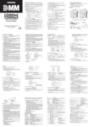
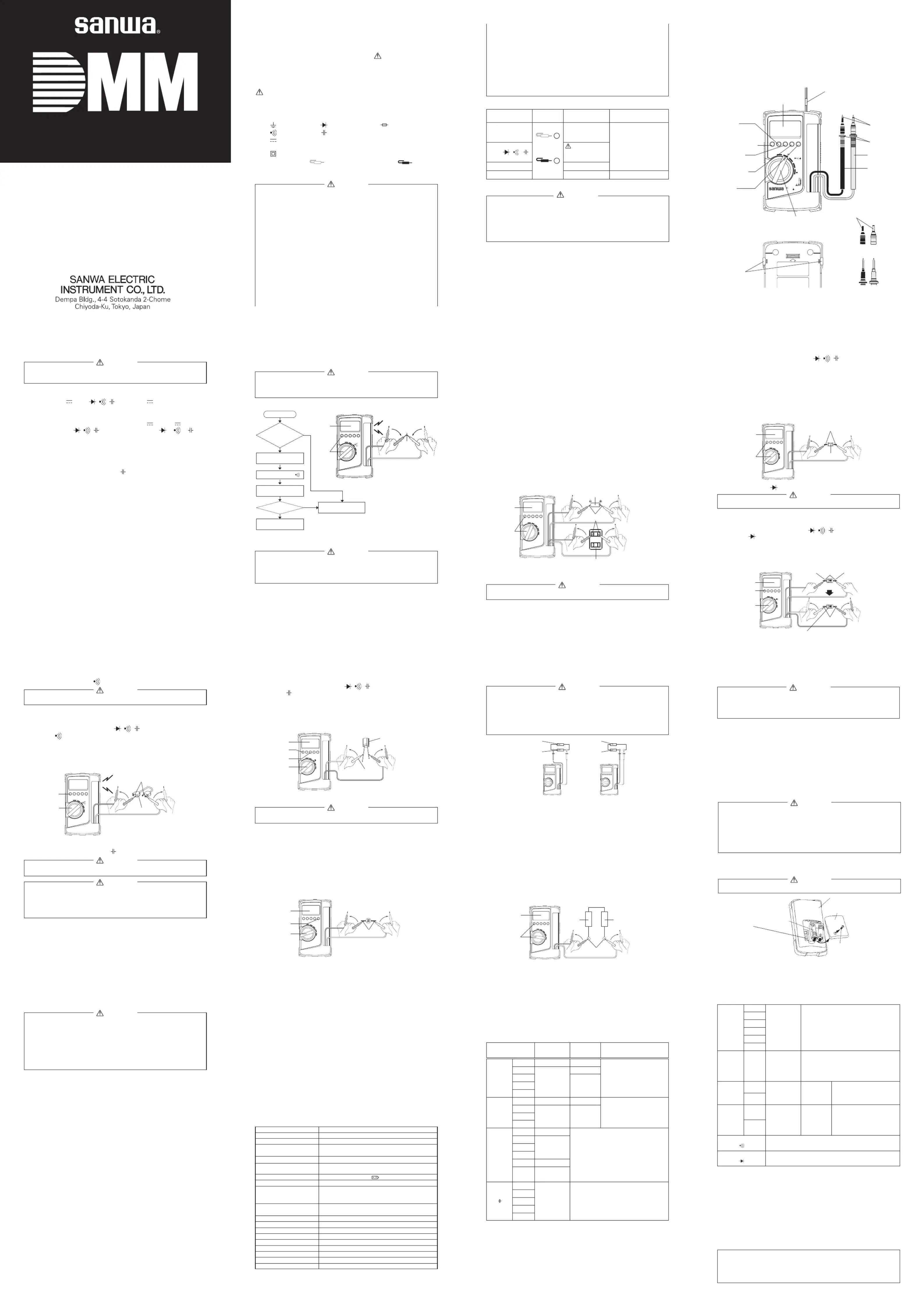
【 】3 NEME OF COMPONENT UNITS
POWER switch and FUNCTION switch
●Sharp contrast LCD with character 17.5 mm high is employed, and unit
symbols are displayed on the screen of the LCD.
●Frequency, capacitance and duty cycle measurement function.
●Attachment body cover is used for protection of the meter and as a tilt
●The current function is protected by a fuse.
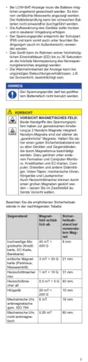
1. Correct measurement may not be performed when using the meter
in the ferromagnetic / intense electric field such as places near a
transformer, a high-current circuit, and a radio.
2. The meter may malfunction or correct measurement may not be
performed when measuring special waveform such as that of the