Dempa Bldg., 4-4 Sotokanda 2-Chome
Neve ope teste cas excep whe replacin batteries Do nor n r e t n g . t
attempt any alteration of original specifications.
To e y d n , e d eensur safet an maintai accuracy calibrat an check th
tester at least once a year.
12.The multimeter restricts in use in indoor.
1-3 Maximum Overload Protection Input
*:AC voltage is regulated by rms valus of sinusoidal wave.
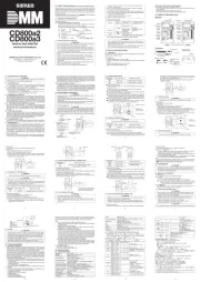
【 】2 APPLICATION AND FEATURES
This instrument is portable multimeter designated for measurement
・This multimeter is very thin type. Body thickness is 8.5 mm.
・Sharp contrast LCD with character 13.6 mm high is employed,
and unit symbols is displayed on the screen of the LCD.
・Addition function: Hz/Duty , Relative and Data Hold.
・Auto power off(15 min.) It is able to cancel it.
・The einstrument has been designed in accordance with th
safety standard IEC 1010-1.
【 】4 DESCRIPTION OF FUNCTIONS
In the case of action or cancel that function as follows, do no t
turn the function switch in the condition applied input.
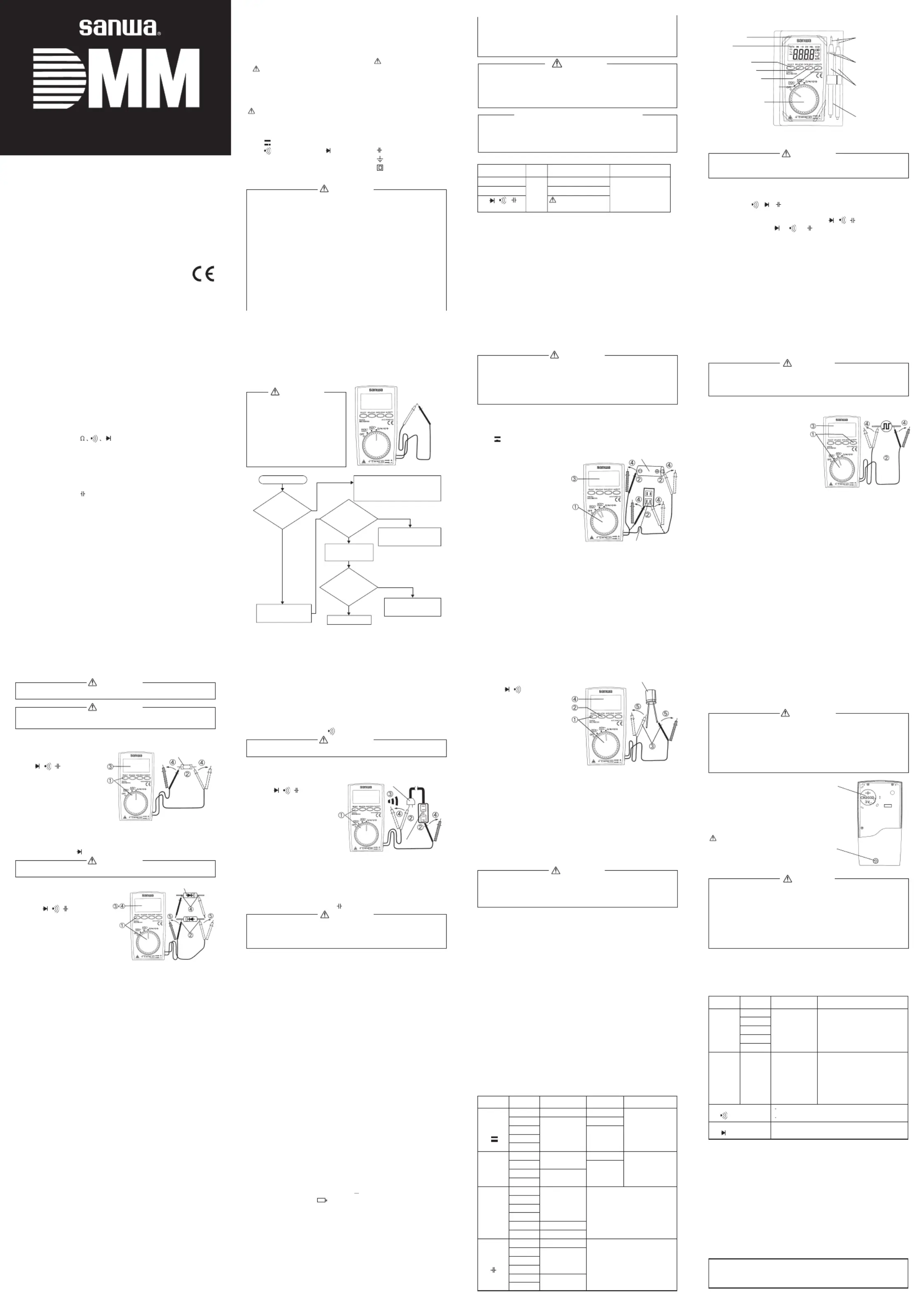
1) Power switch and function switch
Tur thi switc tur an of th powe an selec th functionn s h to n on d f e r d t e s of
Thi switc use fo th switchin cas ths h s it r e g of / / / . In theΩe of e
When this switch is pressed, the data display at that time continues
(DH lights on the display). When the measuring input changes, the
display will not change. When this switch is pressed again, the hold
status is canceled you can return to the measuring status. (DH on the
(DATA HOLD function does not work when measuring frequency.)
Relative measurement switch
Suppose that actual value is X1 when REL switch is pressed. Then,
valu X-X displaye fo actua inpu valu afte that Each time of 1 is d r l t e X r . e
pressing REL switch, value of X1
is updated. This function is except
the Hz/DUTY measurement mode.
< >In the case of use at the DCV and ACV function
・In the case of canceled, please push the switch again.
Th measuremen rang fixe th rang th poin that pushee t e is d to e e in e t d
the switch. About measurement after this, the range is fixed. To
return to the auto range, pleas sto measuremen onc an set the p t e d e
Do not measure any signal that exceeds the maximum of current range.
< >In the case of use function
・When“ ”O.L is , g d n e t .displayed settin an cancellatio ar no possible
・In the case of canceled, please push the switch again.
Th resistanc measuremen rang fixee e t e is d to e e in tth rang the poin
tha pushe th switch Abou measuremen afte this th ranget d e . t t r , e is
fixed. To return to thmnge, please stop measurement once and
< >In the case of use function
・In the case of canceled, please push the switch again.
Th Capacitanc measuremen aut rang mod only Afte cancelee e t is o e e . r d
relative mode, it is possible measurement with the auto range.
5) Hz/DUTY (Frequency/Duty)switch
This switch uses it for the switching of Hz/DUTY. In the case of the
mode change as Hz DUTY voltage measuring mode Hz.→ → →
●When Yit returns it to the voltage function after the Hz/DUT
measurement the range is fixed automatically. (DCV function is
400 mV. ACV function is 4 V.) Please stop measurement once to
cancel the manual range. And please do measurement after the
function is set up again.
The power of the meter will automatically turned off after the beep if no operation
is done for about 15 minutes. To reset the meter, press any button of th e
RELATIVE, DATA HOLD, or Hz/DUTY. To cancel this function, press the SELECT
switch, or change the function switch from the OFF to a desired function while
holding the SELECT switch pressed, and then release the SELECT switch after a
couple of minutes. Set the function switch to OFF when meter is not in use.
【 】5 MEASUREMENT PROCEDURE
Be e to k rsur pre-chec the mete
2.Do not use a damaged meter
Check continuity of test leads.
When a battery exhaust mark
appears in the display, replace
the battery with a new one.
* : note Non-marking may suggest that a battery be exhausted.
5-2-2 Hz/DUTY Measurements
Maximum rating input value 60.00 kHz / 99 %
The setting and measurement (At the time of AC voltage input) of th e
Hz/DUTY are possible at the DCV functiontoo. However, we recommend
the use in the ACV function.
1) Applications: Measures frequency and duty of any circuit.
at ACV function. Push the
and select the Hz function.
(The unit display is Hz display.)
In the case of duty measurement,
then push the Hz/DUTY switch
one more time, and select
(The unit display is % display.)
②Apply the red and black test pins to the circuit to measure.
③Read the value on the display.
④Aft me n r t and ck test omer asureme t, emove he red bla pins fr
●With wmeasuring terminals disconnected, display may overflo
or value may unsteadily fluctuate. There are not malfunctions.
●Input sensitivity varies according to frequency and wave-form.
●Please refer to 8-2 Measurement Range and Accuracy.
●It is only auto range mode.
●When Yit returns it to the voltage function after the Hz/DUT
measurement the range is fixed automatically. (DCV function is
400 mV. ACV function is 4 V.) Please stop measurement once to
cancel the manual range. And please do measurement afte r
the function is set up again.
●DATA HOLD function does not work when measuring frequency.
●The ometer cannot measure frequency that does not go to and fr
Safety: EN61010-1, EN61010-2-030, EN61010-2-033, EN61010-031
≦ ・ IIDC AC 500 V: Designed to protection Class
requirement of IEC 1010-1, Pollution degree II.
Measurement Category(Overvoltage Category) II
8-2 Measurement Range and Accuracy
Accuracy assurance range:23 5 80± ℃ %RH MAX. No condensation.
: Before use, read the following safety precautions
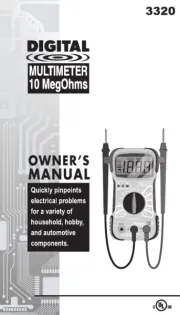
This instruction manual explains how to use your multimeter PM 3
safely. Before use, please read this manual thoroughly. After reading it,
keep it together with the product for reference to it when necessary.
The instruction given under the heading “ ”WARNING
“ ”CAUTION must be fo ow to prevent ac ent rn orll ed cid al bu
1-1 Explanation of Warning Symbols
The meaning of the symbols used in this manual and attached to
the product is as follows.
:Very important instruction for safe use.
・The towarning messages are intended to prevent accidents
operating personnel such as burn and electrical shock.
The caution messages are intended to prevent damage to the instrument.
DCV DC voltage ACV: ~: Ω:AC voltage Resistance
: : :Buzzer Diode Capacitance
Hz Frequency DUTY Duty cycle Ground: : :
+: -: :Plus Minus Double insulation
1-2 Warning Instruction for safe use
To ensure that the meter is used safely, be sure to observe the
instruction when using the instrument.
1. Never use meter on the electric circuit that exceed 3.6 kVA.
2. Pay special attention when measuring the voltage AC 33 Vrms
(46.7 V peak) or DC 70 V or more to avoid injury.
Never apply an input signal exceeding the maximum rating input value.
Neve us mete fo measurin th lin connecte wit equipmenr e r r g e e d h t
(i.e. motors) that generates induced or surge voltage since it may
exceed the maximum allowable voltage.
Neve us mete th mete tes lead ar damage brokenr e rif e r or t s e dor .
6. Never use uncased meter.
Always keep your fingers behind the finger guards on the probe
when making measurements.
Be e to t e t s m e t .sur disconnec th tes pin fro th circui when changing the function
9. Never use meter with wet hands or in a damp environment.
5-2 Voltage, Hz/DUTY measurement
Never apply an input signal exceeding the maximum rating input value.
Be sure to disconnect the test pins from the circuit when changing
Always keep your fingers behind the finger guards on the probe
when making measurements.
5-2-1 Voltage Measurement (DCV,ACV)
Maximum rating input value DC/AC 500 V
DCV : Measures batteries and DC circuits.
ACV : Measures sine-wave AC voltage as lighting voltages.~
“ ” “ ”DCV or ACV function.
②Apply the black test pin
to the negative potential
side of the circuit to measure
and the red test pin to the
③Read the value on the display.
After measurement, remove
th re an blac tes pin froe d d k t s m
●The display fluctuates when
the test leads are removed. This is not malfunction.
Since this instrument employs the means value system for its AC
voltage measurement circuit AC waveform other than sine wav , e
In the AC 4 V ranges a figure of about 3 9 conuts will stay on even if~
no input signal is present.
●The accuracy guaranteed frequency range is 40 Hz to 400 Hz.
2) Repair during the warranty period:
The failed meter will be repaired in accordance with th e
conditions stipulated in 7-1 Warranty and Provision.
3) Repair after the warranty period has expired:
In some cases, repair and transportation cost may becom e
higher than the price of the product. Please contact Sanw a
authorized agent / service provider in advance.
The minimum retention period of service functional parts is 6
years after the discontinuation of manufacture. This retention
period is the repair warranty period. Please note, however, if
such functional parts become unavailable for reasons of
discontinuation of manufacture, etc., the retention period may
become shorter accordingly.
4) Precautions when sending the product to be repaired:
To ensure the safety of the product during transportation ,
place the product in box that is larger than the product a 5
tim or more in volume fill cushion te ials lles and ma r fu y and
then clearly mark “Repair Product Enclosed” on the bo x
surface. The cost of sending and returning the product shall be
http://www.sanwa-meter.co.jp
E-mail: exp_sales@sanwa-meter.co.jp
8-1 General Specifications
Display: 4000 counts max.
Range selection: Auto ranges
Over display:“ ”O.L display
Polarity: Automatic selection (only“
Sampling rate: Approx. 3 times/sec.
Accuracy assurance temperature /humidity range:
23 5 80 %RH max. No condensation.± ℃
Operating temperature/humidity range:
0 40 80 %RH max. No condensation.~ ℃
Storage temperature/humidity range:
-10 50 70 %RH max. No condensation.~ ℃
Environmenta condition Operatin altitudl : g e ,<2000 m
Pollutio degreen 2 Indoor use only
Power supply: Coin type lithium battery CR2032 (3 V), 1 pcs.
Power consumption: Approx.6 mW TYP. (at DCV)
Battery life: Approx.150 hours at DCV
Dimension and mass:108( ) 56( ) 11.5( )mm Approx.50 gH×W×D
Accessories: Instruction manual 1, Case holder 1
-------------------------------------
*Open voltage: Approx. 0.4 V
*The measuring current changes
according to the resistance
after canceling display valu e
To avoid danger of shock hazard,
do not use multimeter with
damage and repair the meter.
Accuracy in the case of sine wave.
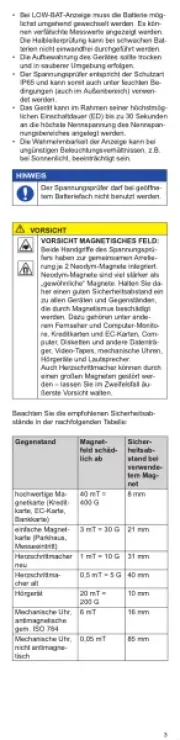
●Do not use the tester near places where strong electromagnetic
waves and trance are generated or strong electrical voltages are
For example Measurement DCmV:
Displayed value 100.0 mV:
Accuracy 400 mV range : ・・・・±(0.7 %rdg+3dgt)
Error (100[mV] 0.7 %+3[dgt] )= 1.0[mV] :± × ±
1.0[mV](In a range of 99.0~101.0 mV)
*3[dgt] in the 400 mV range corresponds to 0.3 mV.
Specifications and external appearance of the product
described above may be revised for modification without
Buzzer sounds at less than 10
Open voltage: Approx. 0.4 V
Open voltage: Approx 1.5 V
-------------------------------------
*Accuracy in the case of sin e
9.999 H 9.999 kHz: 10 Vrmz~ s~ .250 Vrms
About input sensitivity an d
fr u raceq ency cha teri tics :
(Square wave DUTY 50 % input)
●Make sure that the test leads are not cut, referring to the section.
The dealer may conduct the calibration and inspection. For mor e
information, please contact the dealer.
6-3 How to Replace Battery
If the rear case is removed with input applied to the input terminals,
you may get electrical shock. Before starting the work, always
make sure that no inputs is applied.
Be sure to use the fuse is same rating so as to ensure safety and
When operators remove the rear case, do not touch the internal
< >How to replace the battery
screw with a screwdriver.
③Take out the battery and replace it with a
④Attach the rear case and fix it with the screw.
Set a battery with its polarities
facing in the correct directions.
The panel and the case are not resistant to volatile solvent and
must not be cleaned with thinner or alcohol. For cleaning, use
dry, soft cloth and wipe it lightly.
The panel and the case are not resistant to heat. Do not place
the instrument near heat-generating devices (such as a soldering iron)
Do not store the instrument in a place where it may be subjected
to vibration or from where it may fall.
For storing the instrument, avoid hot, cold or humid places or places.
Under direct sunlight or where condensation is anticipated.
Following the above instructions, store the instrument in good environment.
show 00.00 nF. (The“ ”REL
mark illuminates in the upper
right area of the display.)
③Apply the black red test pin
④Read the value on the display.
⑤After mmeasurement, remove the red and black test pins fro
●For measurement of 100 nF or below, the display will not stabilize
due to the influence of ambient noise and floating capacity.
●Necessarily splease discharge the electric charge that wa
charged to the condenser before measurement.
●As the capacitance increases, the measuring time becomes longer.
(Example: approx. 5 sec. at 10 µ. Approx.45 sec. at 150 µF.)
This section is very important for safety. Read and understand the followin g
instruction fully and maintain your instrument properly.
The instrument must be calibrated and inspected at least once a year to
maintain the safety and accuracy.
6-1 Maintenance and inspection
1. Appearance:Is the appearance not damaged by falling?
④Replace ethe red and black test pins, make sure that th
displays the same as that when the test leads are released.
⑤A m l se r bl t pi f mfter easure nt,me re ea the ed and ack est ns ro
Judgment: Whe th item an ar normal th diodn e s ③d④e , e e .is good
●The input terminals release voltage is about 1.5 V.
5-5 Checking Continuity ( )
Never apply voltage to the input terminal.
Application Checkin th continuit wirin an selectin wires: g e y of g d g .
test pins to a circuit or
④A m l se r bl t pi f mfter easure nt,me re ea the ed and ack est ns ro
●The buzzer sounds when the resistance in a circuit to measure
is less than about 10 100 Ω~ Ω
●The input terminals release voltage is about 0.4 V.
5-6 Capacity Measurement ( )
1. Never apply voltage to the input terminal.
2. This is not suitable for measurement of electrolytic condenser
such as a large leakage condenser.
1) Application: Measures capacitance of capacity.
7-1 Warranty and Provision
Sanwa offers comprehensive warranty services to its end-user s
and to its product resellers. Under Sanwa's general warranty policy,
each instrument is warranted to be free from defects in
workmanship or material under normal use for the period of one (1)
year from the date of purchase.
This warranty policy is valid within the country of purchase only ,
and applied only to the product purchased from Sanwa authorized
Sanwa reserves the right to inspect all warranty claims to determine
the extent to which the warranty policy shall apply. This warrant y
shall not apply to disposables batteries, or any product or parts ,
which have been subject to one of the following causes:
1. failure due to improper handling or use that deviates fro A m
2. failure due to inadequate repair or modification by peopl A e
other than Sanwa service personnel.
3. A failure due to causes not attributable to this product such as
fire, flood and other natural disaster.
4. Non-operation due to a discharged battery.
5. failure or damage due to transportation, relocation A or
dropping after the purchase.
C to are as d p vide e o i a nus mers ke to ro th foll wing nform tion whe
1. Customer name, address, and contact information
2. Description of problem
3. Description of product configuration
6. Proof of Date-of-Purchase
7. Where you purchased the product
Please contact Sanwa authorized agent distributor servic / / e
provider, listed in our website, in your country with abov e
information. An instrument sent to Sanwa agent distributo / / r
without those information will be returned to the customer.
1) Prior to requesting repair, please check the following:
C acity of t , pola y of sta tion andap he buil int- battery rit in lla
discontinuity of the test leads.
1. eCorrect measurement may not be performed when using th
meter in the ferromagnetic / intense electric field such as places
near a transformer, a high-current circuit, and a radio.
The meter may malfunction or correct measurement may not be performe d
when measuring special waveform such as that of the inverter circuit.
A battery for monitoring is preinstalled before shipping therefore it may
run down sooner than the battery life specified in the instruction manual.
is a battery to inspect the functions
and specifications of the product.
Factory-preinstalled built-in battery
●This digital multimeter has 4000(5000) counts max. display, however,
its range may change even less than 4000(5000) counts depending
on the using function or the measuring range.
5-3 Resistance Measurement ( )Ω
Never apply voltage to the input terminal.
The reading may vary because of external inductance whe n
measuring high resistance value.
Application: Resistance of resistors and circuits are measured.
2) Measuring ranges:400 Ω~ 40 M (6 range)Ω
①Set the function switch at
②Apply the black red test
④After measurement, remove
the red and black test pins
from the circuit measured.
●If emeasurement is likely to be influenced by noise, shield th
object to measure with negative potential (test lead black).
●The input terminals release voltage is about 0.4 V.
Never apply voltage to the input terminal.
1) Application: The quality of diodes is tested.
②Apply the black test pin to
the cathode of the diode and
the red test pin to the anode.
③Make sure that the display
shows a diode forward voltage drop.
Test leads:Are you having the problem with “the test leads are damaged,
and the cable core and white coating inside of the test leads are exposed”?
(We use double insulation test leads. If you could see the test
leads as above condition, you need to change the new one).
Please do not use as it is, if applicable, of the above items.