L
R
BUS AUDIO IN
AUDIO OUT
REAR*2BUS
CONTROL IN
2
4
5
1
3
AUDIO OUT
REAR/SUB
BUS
IN
2-890-968- (1)51
Installation/Connections
Instalación/Conexiones
⫭塁濊䴾嵓徇㌉
FM/AM
Compact Disc Player
AUDIO OUT REAR*
BUS AUDIO IN
BUS CONTROL IN
A
B
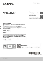
Equipment used in illustrations (not supplied)
Equipo utilizado en las ilustraciones (no suministrado)
㌶♺ᶑ䗨塁仒濃 斨彥濄曂
from car antenna (aerial)
desde la antena del automóvil
Ừ 㯡 ⢍䴾兎 帮
Rear speaker
Altavoz posterior
⻰㌾俖◌
Front speaker
Altavoz frontal
↱㌾俖◌
Active subwoofer
Altavoz potenciador de
graves activo
㙭㷴峩Ẳ ㌾俖◌杗
Power amplifi er
Amplifi cador de potencia
∃䋫㒢 ◌⢋
× 2
× 4
CD/MD changer
Cambiador de CD/MD
DE0NE!㌿䠃㧃
BUS AUDIO IN
BUS CONTROL IN
Source selector*
Selector de fuente*
杗㷴応㐫◌*
XA-C40
* not supplied
no suministrado
! 斨彥曂
*1 RCA pin cord (not supplied)
*2 AUDIO OUT can be switched SUB or
REAR. For details, see the supplied
Operating Instructions.
*1 Cable con terminales RCA
(no suministrado)
*2 AUDIO OUT (Salida de audio) puede
cambiarse a SUB (Secundaria) o REAR
(Posterior). Para obtener información,
consulte el manual de instrucciones
suministrado.
*1!SDB!慁⛯⭲䴾濃 斨彥濄曂
*2!BVEJP!PVU!⍓ṉ庭㌿䀞!TVC!ㅺ!SFBSɁ
姗〩娯⌧攕斨䗨ợ 娎㕲㙜Ɂ䒌
AMP REM
Max. supply current 0.3 A
Corriente máx. de alimentación de 0,3 A
㙤 晟㲥!1/4!B⢋
Fuse (10 A)
Fusible (10 A)
ὁ明䳖!)21!B*
Blue/white striped
Con rayas azules y blancas
唱濊 㠁䱯䗡
Red
Rojo
䱩凖
Yellow
Amarillo
渧凖
White
Blanco
䗡凖
Green
Verde
䴄凖
Purple
Morado
䲏凖
White/black striped
Con rayas blancas y negras
䗡 渵濊 㠁䱯
Grey/black striped
Con rayas grises y negras
㿔濊 㠁䱯渵
Green/black striped
Con rayas verdes y negras
䴄濊 㠁䱯渵
Grey
Gris
㿔凖
Left
Izquierdo
ⵊ
Right
Derecho
⍗
Left
Izquierdo
ⵊ
Right
Derecho
⍗
ANT REM
Black
Negro
渵凖
Blue
Azul
唱凖
Max. supply current 0.1 A
Corriente máx. de alimentación de 0,1 A
㙤 晟㲥 1/2!B⢋
Purple/black striped
Con rayas moradas y negras
䲏濊 㠁䱯渵
Source selector
(not supplied)
Selector de fuente
(no suminidtrado)
杗㷴応㐫◌
) 斨彥*曂
XA-C40
Supplied with the CD/MD changer
Suministrado con el cambiador de CD/MD
斨㔠!DE0NE!㌿䠃㧃
*1
CDX-GT460US
Supplied with XA-C40
Suministrado con el XA-C40
斨㔠!YB.D51
* AUDIO OUT SUB/REAR
㱌び
• 㚐㧃⍎偡ợ 射㣙㌉⚔!23!W!䙘㲥晟㷴Ɂ䒌
•!ᵱ壥ợ⭲䴾⢢⚌圞䳖ᵯ濇ㅺ䷂㋿⚌䥟∹恌Ṛᵮ
濃⣦濕⸋㡩㇚ ᵮ濄Ɂㆯ
•!徇㌉䴾嵓ᶯ↱濇娯敀擭㯡 㐲ṉ₱峛䝑嵓Ɂ帮
• 渧凖⏰䱩凖晟㷴⭲䴾⼩杬⚌ㆤ㙭⃚⫧⭲䴾恡徇㌉⫰
䓆ṉ⻰ㆱ徇㌉Ɂ
• ⭫ㆤ㙭⚔䴾恡徇㌉↔⍰ ㌉⚔湂Ɂᵤ
• 䀞
ᷪ
⫭濇娯䠞姱㯶㙭徇㌉䗨⭲䴾䒌晟◌億≩
䲒徖 䲹䵇Ɂ垰
晟㷴⭲䴾杬䝉濃 濄渧凖
• ⭫㚐㧃八⃚⫧䨯 䒌樸俖塁仒䲨⍬ợ 㖦濇ㆤ徇㌉䗨㯡
帮 ⢋晟嵓⬝愳⼩杬 㔠㬳Ὧ塁仒ὁ明䳖⬝愳䗨䶡⏰Ɂ
• 䓚㯡帮 ⢋晟嵓⬝愳ᵱ⢄ 㖦濇娯⭫㚐㧃䙘㌉八晟㯄䙜
徇㌉Ɂ
晚Ṛ 夡埌!ᵤ
• ♺ 㓜⪻八娎㕲㙜ᶑ䗨㓜⪻㖓 兘䗨Ɂ䢞 ᵤ
• ㆼ㜚!
!⏰ὁ嫛䐔!
!⚌⅞⹄ᶯ↱ⵖ䳷塁⚌㚐㧃ᵮɁ
⚌⫭塁㚐㧃ᶯ↱濇娯€ợ 擯拺揔≽!䒌!⭫ㆼ㜚!!
⏰ὁ嫛䐔!! ⼂㚐㧃ᵮ㈪ᵯɁ姗䲔娎㕲濇娯⌧ 㚐壯
来 曆⌱ ĥ㈪ᵯὁ嫛䐔⏰ㆼ㜚!)*ĦɁ
• ⣦㜀Ḯ⻰壥⭫㚐㧃⼂㯡 ᵮ㈪ᵯ濇
᷃壥ợ 擯拺揔帮 䒌
≽濇♄㫈娯ὁ⪼⣡擯拺揔≽!!ṉ´Ḯ⻰ợ Ɂ䒌
㱌び
㉣⌺ㆼ㜚!!㖦濇娯䇝↉㱌び↉‛↔ ㉫Ɂㆯ
㈰懈
妟
⫭塁ᶯ↱濇⼩杬⭫ㆼ㜚!!Ῐ䗨㈰懈⍵⺲㙖!3!nnɁ⣦㜀㈰懈
䪪䙘ㅺ⍵⡺⺲㙖濇↫㚐㧃⭫䂅㰹䇆♞⫭塁濇ᶊ⍓偡⺬⅞Ɂ
䴾嵓徇㌉♺ữ!
妟濃 濄-A
•! ∽⼩⚌㌉㒢 ◌ᶯ↱徇㌉⚔䴾Ɂ⢋
•! ⍎㙭ợ 㒢 ◌㖦濇➕嫊◌ㆱ㙧䗠⅞➕嫊俖Ɂ䒌 ⢋
㌴ 濃 濄䢞-B-
剉壥徇㌉!3!⍔ㅺ㙘⡾!DE0NE!㌿䠃㧃濇⼩杬ợ 㷴応㐫◌!YB.䒌杗
D51濃 斨彥濄Ɂ曂
䴾嵓徇㌉♺!
!徇㌉兗 帮 愵 曆㯡 䗨 ⯐埌
棺 渵凖 渧凖 凖€徇㌉ ㌉⚔⭲䴾濇䂚⻰徇㌉ ⏰䱩 晟㷴⭲䴾Ɂ
!徇㌉兗晟∹⢍䴾㌋↚⭲䴾ㅺ⢍䴾⊫⠷◌䗨晟㷴⭲
䴾
妟
•! ⣦䂅晟∹⢍䴾ㅺ⢍䴾⊫⠷◌濇ㅺ㙭 ∹⢻䬅⢍䴾濇ἣᵱㆯ
杬徇㌉㫈⭲䴾Ɂ
•!「㯡帮䗨⻰濊Ῐ䌟䏧䧻ᶑ⣦㜀㙭!GN0BN!⢍䴾濇⋗娯⌧
䙯ĥ㌋↚䴾⏰晟㷴⭲䴏杬䝉ĦɁ
!徇㌉兗 ⢋応屠䗨∃䋫㒢 ◌䗨!BNQ!SFNPUF!JO濃㒢
⢋ ◌徽㌋府 濄
㚐徇㌉ 㔠㒢 ◌Ɂ徇㌉ṟẹ⃚⫧䱟䳕⍓偡㙧㍱⡂㚐㧃Ɂ䒌 ⢋
!
徇㌉ ⚌湂 擯敀䗨斨Ṛằ仒ᵮ彾晟䗨兗 㿏
!
,23!W!晟
㷴䩓⪴
妟
•! 剉㯶㙭斨Ṛằ仒濇↫娯徇㌉ ⤯䲦彾晟䗨!,23!W!晟㷴兗
濃晟㯄濄䩓 Ɂ⪴
! ⼩杬棺 渵凖 兗 帮 愵 曆€⭫ ㌉⚔⭲䴾徇㌉ 㯡 䗨 ⯐埌 Ɂ
•!「㯡帮䗨⻰濊Ῐ䌟䏧䧻ᶑ⣦㜀㙭!GN0BN!⢍䴾濇⋗娯⌧
䙯ĥ㌋↚䴾⏰晟㷴⭲䴏杬䝉ĦɁ
!徇㌉兗 ⪴⤯䲦彾晟䗨!,23!W!晟㷴䩓
⼩杬 €⭫ ㌉⚔⭲䴾徇㌉ 㯡 䗨 ⯐埌 Ɂ棺 渵凖 兗 帮 愵 曆
㌋↚䴾⏰晟㷴⭲䴏杬䝉
•! ㆷ擯娣婋◌晟㷴㖦濇晟∹⢍䴾䗨㌋↚⭲䴾濃唱 濄ἣ偡㌴ỿ!凖
,23!W!䙘㲥晟Ɂ
•! 剉「䗨㯡 ⻰濊Ῐ䌟䏧䧻ᵮ㙭!GN0BN!⢍䴾濇杬⭫晟∹⢍䴾帮
㌋↚⭲䴾濃唱 濄ㅺ幸∍晟㷴⭲䴾濃䱩 濄徇㌉↔䍢㙭⢍䴾⊫凖 凖
⠷◌ᵮ䗨晟㷴䩓 ᵮɁ姗䲔⬝娯⍵戛⒒⒪婒姆Ɂ⪴
•! 㚐㧃ᵱ偡ợ ᵱ
⃛
´䷠晟◌䘶䗨晟∹⢍䴾Ɂ䒌
ὁ㉥奼ㄚ䗨䴾嵓徇㌉㰹
䓚徇㌉⣡ 晟㷴⭲䴾㖦濇⋗ợ湂 擯敀敀擭濇晟㷴ḱ⭫⭱奼ㄚ渧凖 㿏
晟嵓ỿ晟Ɂ
徇㌉㌾俖◌㖦䗨㱌び
ᷯ
杩
•! 徇㌉㌾俖◌ṉ↱濇娯€敀擭㚐㧃晟㷴Ɂ
•!ợ䒌 崗斟ㇻ䀞!5.9Ã!ᵸ
⃛
㙭 ⢄∃䋫喹䍪⬝愳䗨㌾俖◌濇ṉ₱㍱
⡂㌾俖◌Ɂ
•! ᵱ壥⭫㌾俖◌䩓 徇㌉↔ ᵮ濇ㅺ⭫⍗㌾俖◌䩓 八ⵊ㌾俖⪴ 帮帏 ⪴
◌䩓 䙜徇㌉Ɂ⪴
•! Ⅻ≣⭫㚐㧃䗨㌉⚔⭲䴾徇㌉ ㌾俖◌䗨射濃.濄㌉䴾䩓Ɂ兗
•! ㌾俖◌ᵱ⍓ᶊ俓徇㌉Ɂ
•! 娯徇㌉䂅㷴㌾俖◌Ɂ剉⭫㙭㷴㌾俖◌濃㒢 ◌濄徇㌉⢋
↔㌾俖◌䩓 ᵮ㙧㍱⡂㚐㧃Ɂ⪴
•! 剉㚐㧃ợ ⵊɀ⍗㌾俖◌䗨
⃕
射㣙濃.濄⭲䴾濇䀞
ᷪ
忣₱㒩䒌 䒌
昀濇Ⅻ≣ợ ⵖ⫭塁⚌㯡 䗨㌾俖◌⭲䴾Ɂ䒌 帮
•! 娯≣⭫㚐㧃㌾俖◌⭲䴾䙜
᷶
徇㌉Ɂ
㙭敀徇㌉㱌び
ᷯ
杩
⣦㜀㚎㫇䠞徇㌉㌾俖◌⏰㒢 ◌濇↫染 ⶹᵮ㙧⅞䍢⢋ 䢞
ĥGBJMVSFĦɁ㫈㖦濇娯㫇䠞徇㌉㌾俖◌⏰㒢 ◌Ɂ⢋
2006 Sony Corporation Printed in Taiwan
Cautions
• This unit is designed for negative ground (earth) 12 V
DC operation only.
• Do not get the leads under a screw, or caught in moving
parts (e.g. seat railing).
• Before making connections, turn the car ignition off to
avoid short circuits.
• Connect the yellow red and power supply leads only
after all other leads have been connected.
• Run all ground (earth) leads to a common
ground (earth) point.
• Be sure to in su late any loose un con nect ed leads with
electrical tape for safety.
Notes on the power supply lead (yellow)
• When connecting this unit in combination with other
stereo components, the connected car circuit’s rating
must be higher than the sum of each component’s fuse.
• When no car circuits are rated high enough, connect
the unit directly to the battery.
Parts Iist
• The numbers in the list are keyed to those in the
instructions.
• The bracket and the protection collar are
attached to the unit before shipping. Before mounting
the unit, use the release keys to remove the bracket
and the protection collar from the unit. For
details, see “Removing the protection collar and the
bracket ( )” on the reverse side of the sheet.
• Keep the release keys for future use as they
are also necessary if you remove the unit from
your car.
Caution
Handle the bracket carefully to avoid injuring your
fi ngers.
Note
Before installing, make sure that the catches on both sides of
the bracket are bent inwards 2 mm (3/ in). If the catches are 32
straight or bent outwards, the unit will not be installed securely
and may spring out.
Connection example
Notes ( -A)
• Be sure to connect the ground (earth) lead before connecting
the amplifi er.
• The alarm will only sound if the built-in amplifi er is used.
Tip ( -B-)
For connecting two or more CD/MD changers, the source
selector XA-C40 (not supplied) is necessary.
Connection diagram
To a metal surface of the car
First connect the black ground (earth) lead, then connect the
yellow and red power supply leads.
To the power antenna (aerial) control lead or
power supply lead of antenna (aerial) booster
Notes
• It is not necessary to connect this lead if there is no power
antenna (aerial) or antenna (aerial) booster, or with a
manually-operated telescopic antenna (aerial).
• When your car has a built-in FM/AM antenna (aerial) in
the rear/side glass, see “Notes on the control and power
supply leads.”
To AMP REMOTE IN of an optional power
amplifi er
This connection is only for amplifi ers. Connecting any other
system may damage the unit.
To the +12 V power terminal which is
energized in the accessory position of the
ignition switch
Notes
• If there is no accessory position, connect to the +12 V
power (battery) terminal which is energized at all times.
Be sure to connect the black ground (earth) lead to a
metal surface of the car fi rst.
• When your car has a built-in FM/AM antenna (aerial) in
the rear/side glass, see “Notes on the control and power
supply leads.”
To the +12 V power terminal which is
energized at all times
Be sure to connect the black ground (earth) lead to a metal
surface of the car fi rst.
Notes on the control and power supply leads
• The power antenna (aerial) control lead (blue) supplies +12 V
DC when you turn on the tuner.
• When your car has built-in FM/AM antenna (aerial) in the rear/
side glass, connect the power antenna (aerial) control lead
(blue) or the accessory power supply lead (red) to the power
terminal of the existing antenna (aerial) booster. For details,
consult your dealer.
• A power antenna (aerial) without a relay box cannot be used
with this unit.
Memory hold connection
When the yellow power supply lead is connected, power will
always be supplied to the memory circuit even when the ignition
switch is turned off.
Notes on speaker connection
• Before connecting the speakers, turn the unit off.
• Use speakers with an impedance of 4 to 8 ohms, and with
adequate power handling capacities to avoid its damage.
• Do not connect the speaker terminals to the car chassis, or
connect the terminals of the right speakers with those of the
left speaker.
• Do not connect the ground (earth) lead of this unit to the
negative (–) terminal of the speaker.
• Do not attempt to connect the speakers in parallel.
• Connect only passive speakers. Connecting active speakers
(with built-in amplifi ers) to the speaker terminals may damage
the unit.
• To avoid a malfunction, do not use the built-in speaker leads
installed in your car if the unit shares a common negative (–)
lead for the right and left speakers.
• Do not connect the unit’s speaker leads to each other.
Note on connection
If speaker and amplifi er are not connected correctly, “FAILURE”
appears in the display. In this case, make sure the speaker and
amplifi er are connected correctly.
Precauciones
• Esta unidad p1-ha sido diseñada para alimentarse sólo con
cc de 12 V de masa negativa.
• No coloque los cables debajo de ningún tornillo, ni
los aprisione con partes móviles (p. ej. los raíles del
asiento).
• Antes de realizar las conexiones, desactive el
encendido del automóvil para evitar cortocircuitos.
• Conecte los cables de fuente de alimentación amarillo
y solamente después de haber conectado los rojo
demás.
• Conecte todos los cables de conexión a masa
a un punto común.
• Por razones de seguridad, asegúrese de aislar con cinta
aislante los cables sueltos que no estén conectados.
Notas sobre el cable de fuente de alimentación
(amarillo)
• Cuando conecte esta unidad en combinación con otros
componentes estéreo, la capacidad nominal del circuito
conectado del automóvil debe ser superior a la suma
del fusible de cada componente.
• Si no hay circuitos del automóvil con capacidad
nominal sufi cientemente alta, conecte la unidad
directamente a la batería.
Lista de componentes
• Los números de la lista corresponden a los de las
instrucciones.
• La unidad se comercializa con el soporte y el marco
de protección p1-ya colocados. Antes de montarla,
utilice las llaves de liberación para extraer el
soporte y el marco de protección de la misma.
Para obtener más información, consulte “Extracción
del marco de protección y del soporte ()”.
• Conserve las llaves de liberación para
utilizarlas en el futuro, p1-ya que también las
necesitará si retira la unidad del automóvil.
Precaución
Tenga mucho cuidado al manipular el soporte para
evitar posibles lesiones en los dedos.
Nota
Antes de instalar la unidad, compruebe que los enganches de
ambos lados del soporte están doblados hacia adentro 2 mm.
Si no lo están o están doblados hacia afuera, la unidad no se
instalará correctamente y puede saltar.
Ejemplo de conexiones
Notas ( -A)
• Asegúrese de conectar primero el cable de conexión a masa
antes de realizar la conexión del amplifi cador.
• La alarma sonará únicamente si se utiliza el amplifi cador
incorporado.
Sugerencia ( -B- )
Si desea conectar dos o más cambiadores de CD/MD,
necesitará el selector de fuente XA-C40 (no suminidtrado).
Diagrama de conexión
A una superfi cie metálica del automóvil
Conecte primero el cable de conexión a masa negro, y
después los cables amarillo y rojo de fuente de alimentación.
Al cable de control de la antena motorizada
o al cable de fuente de alimentación del
amplifi cador de señal de la antena
Notas
• Si no se dispone de antena motorizada ni de amplifi cador
de antena, o se utiliza una antena telescópica accionada
manualmente, no será necesario conectar este cable.
• Si el automóvil incorpora una antena de FM/AM en el
cristal trasero o lateral, consulte “Notas sobre los cables
de control y de fuente de alimentación”.
A AMP REMOTE IN de un amplifi cador de
potencia opcional
Esta conexión es sólo para amplifi cadores. La conexión de
cualquier otro sistema puede dañar la unidad.
Al terminal de alimentación de +12 V que
recibe energía en la posición de accesorio
del interruptor de encendido
Notas
• Si no hay posición de accesorio, conéctelo al terminal de
alimentación (batería) de +12 V que recibe energía sin
interrupción.
Asegúrese de conectar primero el cable de conexión a
masa negro a una superfi cie metálica del automóvil.
• Si el automóvil incorpora una antena de FM/AM en el
cristal trasero o lateral, consulte “Notas sobre los cables
de control y de fuente de alimentación”.
Al terminal de alimentación de +12 V que
recibe energía sin interrupción
Asegúrese de conectar primero el cable de conexión a masa
negro a una superfi cie metálica del automóvil.
Notas sobre los cables de control y de fuente de
alimentación
• El cable de control de la antena motorizada (azul) suministrará
cc de + 12 V cuando conecte la alimentación del sintonizador.
• Si el automóvil dispone de una antena de FM/AM incorporada
en el cristal trasero o lateral, conecte el cable de control de
antena motorizada (azul) o el cable de fuente de alimentación
auxiliar (rojo) al terminal de alimentación del amplifi cador de
antena existente. Para obtener más información, consulte a su
distribuidor.
• Con esta unidad no es posible utilizar una antena motorizada
sin caja de relé.
Conexión para protección de la memoria
Si conecta el cable de fuente de alimentación amarillo, el circuito
de la memoria recibirá siempre alimentación, aunque apague el
interruptor de encendido.
Notas sobre la conexión de los altavoces
• Antes de conectar los altavoces, desconecte la alimentación
de la unidad.
• Utilice altavoces con una impedancia de 4 a 8 Ω con la
capacidad de potencia adecuada para evitar que se dañen.
• No conecte los terminales de altavoz al chasis del automóvil,
ni conecte los terminales del altavoz derecho con los del
izquierdo.
• No conecte el cable de conexión a masa de esta unidad al
terminal negativo (–) del altavoz.
• No intente conectar los altavoces en paralelo.
• Conecte solamente altavoces pasivos. Si conecta altavoces
activos (con amplifi cadores incorporados) a los terminales de
altavoz, puede dañar la unidad.
• Para evitar fallas de funcionamiento, no utilice los cables de
altavoz incorporados instalados en el automóvil si la unidad
comparte un cable negativo común (–) para los altavoces
derecho e izquierdo.
• No conecte los cables de altavoz de la unidad entre sí.
Nota sobre la conexión
Si el altavoz no está conectado correctamente, aparecerá
“FAILURE” en la pantalla. Si es así, compruebe la conexión del
altavoz.
Enganche
Catch