Spaun TP 216 Manual
| Mærke: | Spaun |
| Kategori: | Kabler til computere og periferiudstyr |
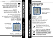
| Model: | TP 216 |
| Produktfarve: | Blå |
| Driftstemperatur (T-T): | -20 - 50 °C |
| LED-indikatorer: | Ja |
| Driftsspænding: | 10 V |
Har du brug for hjælp?
Hvis du har brug for hjælp til Spaun TP 216 stil et spørgsmål nedenfor, og andre brugere vil svare dig
Kabler til computere og periferiudstyr Spaun Manualer
25 September 2025
Kabler til computere og periferiudstyr Manualer
- Metra
- Schneider
- Laserliner
- Qoltec
- Comprehensive
- 3M
- RGBlink
- IFM
- Tempo
- Hosa
- Equip
- Cisco
- Nedis
- Phoenix Contact
- Griffin
Nyeste Kabler til computere og periferiudstyr Manualer

15 December 2025

10 December 2025

10 December 2025

29 November 2025

13 November 2025

11 November 2025

6 November 2025

3 November 2025

3 November 2025

3 November 2025