SCHNELLEINSTIEG
ISG Connect
www.stiebel-eltron.com ISG Connect | 1
DEUTSCH
DEUTSCH
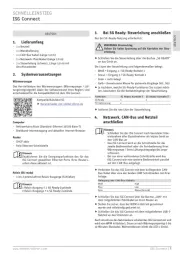
1. Lieferumfang
- 1 x Netzteil
- 1 x Wandhalterung
- 1 x CAN-Bus-Kabel (Länge 3,0 m)
- 1 x Netzwerk-/Patchkabel (Länge 3,0 m)
- 1 x Steuerleitung (schwarz, Länge 3,0 m) mit
Anschlussstecker
2. Systemvoraussetzungen
Wärmeerzeuger
Das Herstelldatum des Wärmeerzeugers (Wärmepumpe/ Lüf-
tungsintegralgerät) sowie der Softwarestand Ihres Reglers sind
entscheidend für die Kompatibilität mit dem ISG Connect.
Kompatibilitätsliste ISG
f Herunterladen von stiebel-eltron.de
Computer
- Netzwerkanschluss (Standard-Ethernet 10/100 Base-T)
- Breitband-Internetzugang und aktuellen Internet-Browser
Router
- DHCP aktiv
- freie Ethernet-Schnittstelle
Hinweis
Deaktivieren Sie die Energiesparfunktion des für das
ISGConnect gewählten Ethernet-Ports Ihres Routers,
sofern diese aktiviert ist.
Relais (SG ready)
- 1 bis 2 potenzialfreie Relais-Ausgänge (Schließer)
Hinweis
1 Relais-Ausgang ≘ 2 SGReady-Zustände
2 Relais-Ausgänge ≘ 4 SGReady-Zustände
3. Bei SG Ready: Steuerleitung anschließen
Nur bei SG-Ready-Nutzung erforderlich:
WARNUNG Stromschlag
Geben Sie keine Spannung auf die Kontakte der Steu-
erleitung.
f Schließen Sie die Steuerleitung über die Buchse „SG READY“
an das Gerät an.
Die Litzen der Steuerleitung sind folgendermaßen belegt:
- Weiß = Eingang 1 / SG Ready-Kontakt 1
- Braun = Eingang 2 / SG Ready-Kontakt 2
- Grün = nicht belegt
- Gelb = Gemeinsame Masse für getrennte Eingänge SG1, SG2
f Je nachdem, welche SG-Ready-Funktionen Sie nutzen möch-
ten, beschalten Sie die Kontakteingänge der Steuerleitung.
Funktion SGReady Kontakt 1 SGReady Kontakt 2
SGReady x x
PV-Optimierung x -
f Isolieren Sie die rote Litze der Steuerleitung.
4. Netzwerk, CAN-Bus und Netzteil
anschließen
Hinweis
- Schließen Sie das ISG Connect nach beendeter Inbe-
triebnahme aller Busteilnehmer als letztes Gerät an
den CAN-Bus an
- Das ISG Connect wird an die Schnittstelle für die
zweite Bedieneinheit oder die Fernbedienung Ihrer
Wärmepumpe/ Ihres Lüftungsintegralgeräts ange-
schlossen.
- Bei nur einer vorhandenen Schnittstelle wird das
ISG Connect wie eine weitere Bedieneinheit parallel
auf den CAN-Bus aufgelegt.
f Verbinden Sie das ISG Connect mit dem beiliegenden CAN-
Bus-Kabel über eine der beiden COM-Schnittstellen mit Ihrer
Anlage.
Belegung des CAN-Bus-Kabels
Weiß High
Blau Low
Grün Masse (Ground)
f Schließen Sie das ISG Connect über die Buchse „LAN“ mit
dem mitgelieferten Patchkabel an Ihren Router an.
f Stellen Sie sicher, dass der WPM in Betrieb genommen
wurde und vollständig gestartet ist.
f Schließen Sie das ISG Connect mit dem mitgelieferten USB-C-
Netzteil an das Stromnetz an.
Nach Anschluss des Netzsteckers schaltet das ISG Connect ein und
wird vom WPM initialisiert. Dauer je nach Wärmepumpentyp 5 bis
10 Minuten (Kaskade). Währenddessen blinkt die LED 1 (links).