Supermicro SuperServer 2029P-C1R Manual
Supermicro
Server
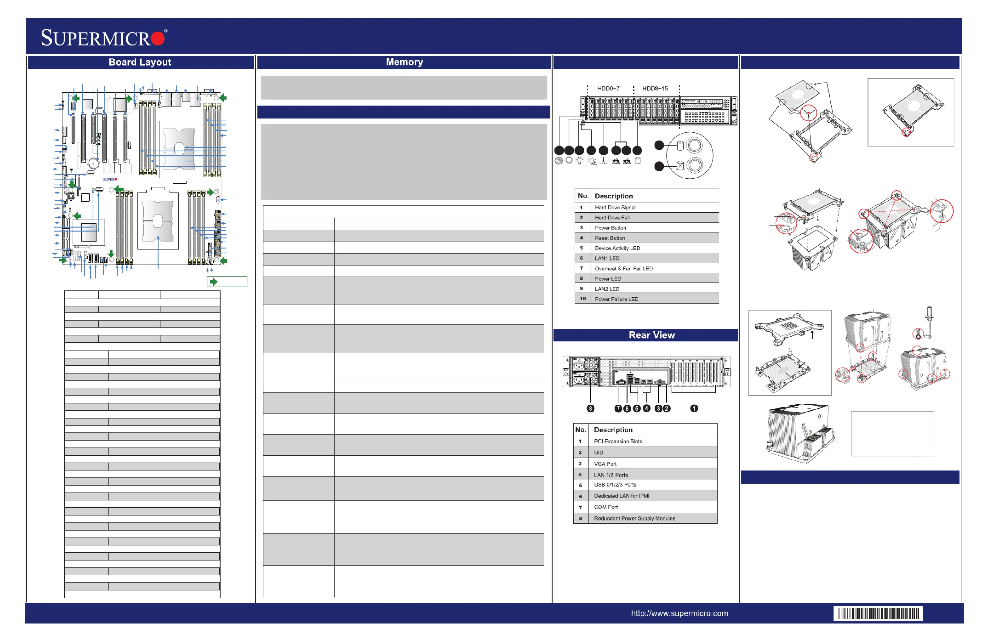
SuperServer 2029P-C1R
| Mærke: | Supermicro |
| Kategori: | Server |
| Model: | SuperServer 2029P-C1R |
Har du brug for hjælp?
Hvis du har brug for hjælp til Supermicro SuperServer 2029P-C1R stil et spørgsmål nedenfor, og andre brugere vil svare dig
Server Supermicro Manualer
5 Oktober 2025
4 Oktober 2025
4 Oktober 2025
4 Oktober 2025
4 Oktober 2025
4 Oktober 2025
3 Oktober 2025
3 Oktober 2025
3 Oktober 2025
3 Oktober 2025
Server Manualer
- Sonnet
- Eminent
- Silex
- Blackmagic Design
- Middle Atlantic
- Vimar
- Buffalo
- MSI
- Megasat
- Dual Bay
- Allnet
- Lindy
- Dahua Technology
- Imation
- ATen
Nyeste Server Manualer

28 Oktober 2025
26 Oktober 2025
21 Oktober 2025

12 Oktober 2025
12 Oktober 2025
5 Oktober 2025

4 Oktober 2025
2 Oktober 2025
2 Oktober 2025

2 Oktober 2025