Supermicro X14SBGM Manual
Supermicro
Ikke kategoriseret
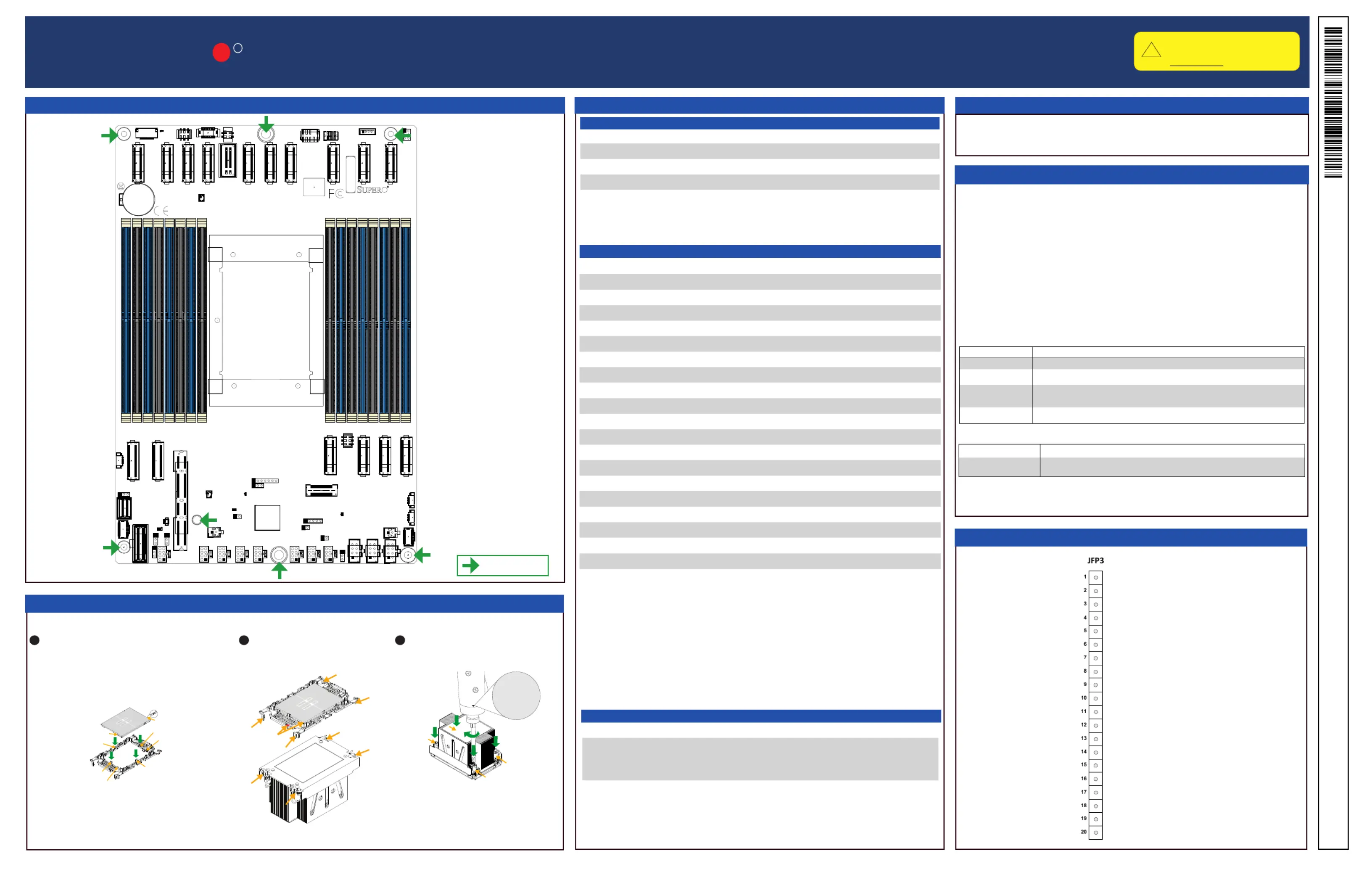
X14SBGM
| Mærke: | Supermicro |
| Kategori: | Ikke kategoriseret |
| Model: | X14SBGM |
Har du brug for hjælp?
Hvis du har brug for hjælp til Supermicro X14SBGM stil et spørgsmål nedenfor, og andre brugere vil svare dig
Ikke kategoriseret Supermicro Manualer
3 Oktober 2025
3 Oktober 2025
3 Oktober 2025
3 Oktober 2025
3 Oktober 2025
2 Oktober 2025
2 Oktober 2025
2 Oktober 2025
1 Oktober 2025
1 Oktober 2025
Ikke kategoriseret Manualer
- InFocus
- Black Lion Audio
- ESKA
- Möhlenhoff
- REDARC
- Dito Sama
- OM SYSTEM
- Drive Medical
- AMT
- Evenflo
- ModeCom
- Icy Dock
- JWIN
- Majella
Nyeste Ikke kategoriseret Manualer

8 December 2025

8 December 2025

8 December 2025

8 December 2025

8 December 2025

8 December 2025

8 December 2025

8 December 2025

8 December 2025

8 December 2025