Tata Zest (2015) Manual
Læs gratis den danske manual til Tata Zest (2015) (166 sider) i kategorien auto. Denne vejledning er vurderet som hjælpsom af 13 personer og har en gennemsnitlig bedømmelse på 4.7 stjerner ud af 7 anmeldelser.
Har du et spørgsmål om Tata Zest (2015), eller vil du spørge andre brugere om produktet?

Produkt Specifikationer
| Mærke: | Tata |
| Kategori: | auto |
| Model: | Zest (2015) |
Har du brug for hjælp?
Hvis du har brug for hjælp til Tata Zest (2015) stil et spørgsmål nedenfor, og andre brugere vil svare dig
auto Tata Manualer


auto Manualer
- VDL
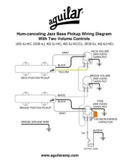
- Aguilar
- Abarth
- Renault
- BMW
- Jeep
- Mercedes-Benz
- ACME
- Porsche
- Rover
- Infiniti
- Alfa Romeo
- Chery
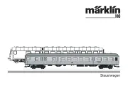
- Märklin
- Acura
Nyeste auto Manualer