1 Produktbeschreibung
Der MBV 5 ist in geeignet zum Verstärken von Radio- und TV-Signalen in den UKW, VHF und UHF Bändern. Jedes einzel-
ne Band kann in der Verstärkung genau geregelt werden. Zudem bietet der UHF-Eingang die Möglichkeit zur Fernspei-
sung einer vorgeschalteten Komponente.
Der Verstärker ist ausschließlich für die Installation in Innenräumen zugelassen.
2 Sicherheitshinweise
• Die Installation des Verstärkers muss gemäß IEC60728-11 und nationalen Sicherheitsstandards erfolgen.
• Der Verstärker wird mit 230 V~ versorgt. Diese Spannung ist lebensgefährlich.
• Alle Reparaturen müssen von qualifiziertem Personal durchgeführt werden.
• Das Gerät ist Schutzisoliert und entspricht der Schutzklasse II.
• Entfernen Sie niemals die Abdeckung des Netzteilteils, ohne das Gerät vom Stromnetz zu trennen.
• Schließen Sie das Gerät nicht an das Stromnetz an, wenn das Netzanschlusskabel oder der Stecker beschädigt sind.
• Schließen Sie das Gerät erst an das Stromnetz an, wenn alle Kabel korrekt angeschlossen sind.
• Um das Gerät vollständig vom Netz zu trennen, ziehen Sie den Netzstecker aus der Steckdose.
• Die Netzsteckdose muss leicht zugänglich sein.
• Gerät vor Feuchtigkeit, Flüssigkeiten, Tropf- und Spritzwasser schützen.
• Keine mit Flüssigkeiten gefüllten Gegenstände auf das Gerät stellen.
• Gerät nicht in Feuchträumen betreiben.
• Gerät nur in gemäßigtem, nicht tropischem Klima verwenden.
• Stellen Sie keine brennenden Gegenstände, z. B. brennende Kerzen, auf das Gerät.
• Wenn das Gerät längerer Zeit unter kalten Bedingungen gelagert wurde, bewahren Sie es mindestens 2 Stunden lang
in einem warmen Raum auf, bevor Sie es an das Stromnetz anschließen.
• Stecken Sie keine Gegenstände in die Lüungsönungen.
• Stellen Sie sicher, dass die Lüungsönungen nicht durch Gegenstände wie Zeitungen, Tischdecken, Gardinen oder
ähnliches abgedeckt werden.
• Montieren Sie das Gerät nur an senkrechten Flächen.
• Montieren Sie das Gerät mit einem Freiraum von mindestens 10 cm über, unter und vor dem Gerät.
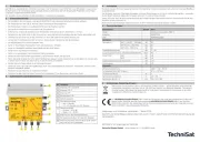
3 Außenansicht und Bedienelemente
Nr Funktion
①
Eingang, VHF I und UKW
②
Eingang, VHF III
③
Eingang, UHF
④
Messausgang -30
⑤
Betriebsausgang
⑥
LED-Betriebsanzeige
• grün = Betrieb
• rot = DC-Überlast am UHF-Eingang
⑦
Dämpfungssteller
• Schalter = 0/10 dB
• Regler = 0 ... 10 dB
⑧
Anschluss für den Potentialausgleich
⑨
Fernspeisung Ein/Aus, 12 V auf UHF-Eingang
⑩
Netzanschlusskabel, fest mit dem Gerät verbun-
den und hier nicht abgebildet.
4 Installation
Montieren Sie den Verstärker waagerecht an der Montagefläche mit den Anschlüssen nach unten um eine gute Belüung
zu gewährleisten.
Der Verstärker muss mit 2 Flachkopf-Schrauben mit einem Durchmesser von 3,5 bis 4 mm befestigt werden - verwenden
Sie bei Bedarf passende Dübel. Die Schrauben sind nicht im Lieferumfang enthalten.
Stellen Sie sicher, dass die Versorgungsspannung der Angabe auf dem Typenschild entspricht und schließen Sie die den
Verstärker an das Stromnetz an.
Nicht benutze Signaleingänge müssen mit einem 75 Ohm Abschlusswiderstand versehen werden.
5 Technische Daten
Bezeichnung Einheit Wert
Model Mehrbereichsverstärker MBV 5
Artikel-Nr. 0002/3129
EAN 4019588231290
Verstärker
Verstärkung VHF I + FM (47 ... 108 MHz) dB 30
VHF III (174 ... 230 MHz) dB 30
UHF (470 ... 862 MHz) dB 34
Pegeldämpfungssteller dB 0 ... 20
Ausgangspegel maximal (DIN 45004 B/60dB IMA) dBµV 115
Rauschmaß VHF dB ≤ 6
UHF dB ≤ 4
Rückflussdämpfung (alle Anschlüsse) dB ≥ 10
Messausgang dB -30
Allgemein
Versorgungsspannung 230V ~ / 50 ... 60 Hz
Fernspeisung über UHF-Eingang 12 V = / 60 mA
Leistungsaufnahme W 7
Nenntemperaturbereich °C -20 ... 50
Abmessung (B x H x T) mm 135 x 52 x 180
6 Entsorgungs-/Recycling-Hinweis
Elektronische Geräte gehören nicht in den Hausmüll, sondern müssen – gemäß Richtlinie 2012/19/EU des
Europäischen Parlaments und Rates vom 4. Juli 2012 über Elektro- und Elektronik-Altgeräte – fachgerecht
entsorgt werden. Bie geben Sie dieses Gerät am Ende seiner Verwendung zur Entsorgung an den dafür
vorgesehenen öentlichen Sammelstellen ab.
Der MEHRBEREICHSVERSTÄRKER MBV 5 trägt das CE-Zeichen und erfüllt alle erforderlichen EU-Normen.
Hiermit erklärt TechniSat, dass der Funkanlagentyp MEHRBEREICHSVERSTÄRKER MBV 5 der Richtlinie
2014/53/EU entspricht. Der vollständige Text der EU-Konformitätserklärung ist unter der folgenden Internet-
adresse verfügbar. hp://konf.tsat.de/?ID=22745
Änderungen und Druckfehler vorbehalten. Stand 01/22
Abschri und Vervielfältigung dieses Dokument, auch in Teilern, bedarf einer schrilichen Genehmigung des
Herausgebers.
TechniSat ist ein eingetragenes Marke der
TechniSat Digital GmbH · Julius-Saxler-Str. 3 · D-54550 Daun
❶❶❷❷❸❸
❹❹
❺❺
❽❽
❼❼
❾❾
❿❿
❻❻
❼❼