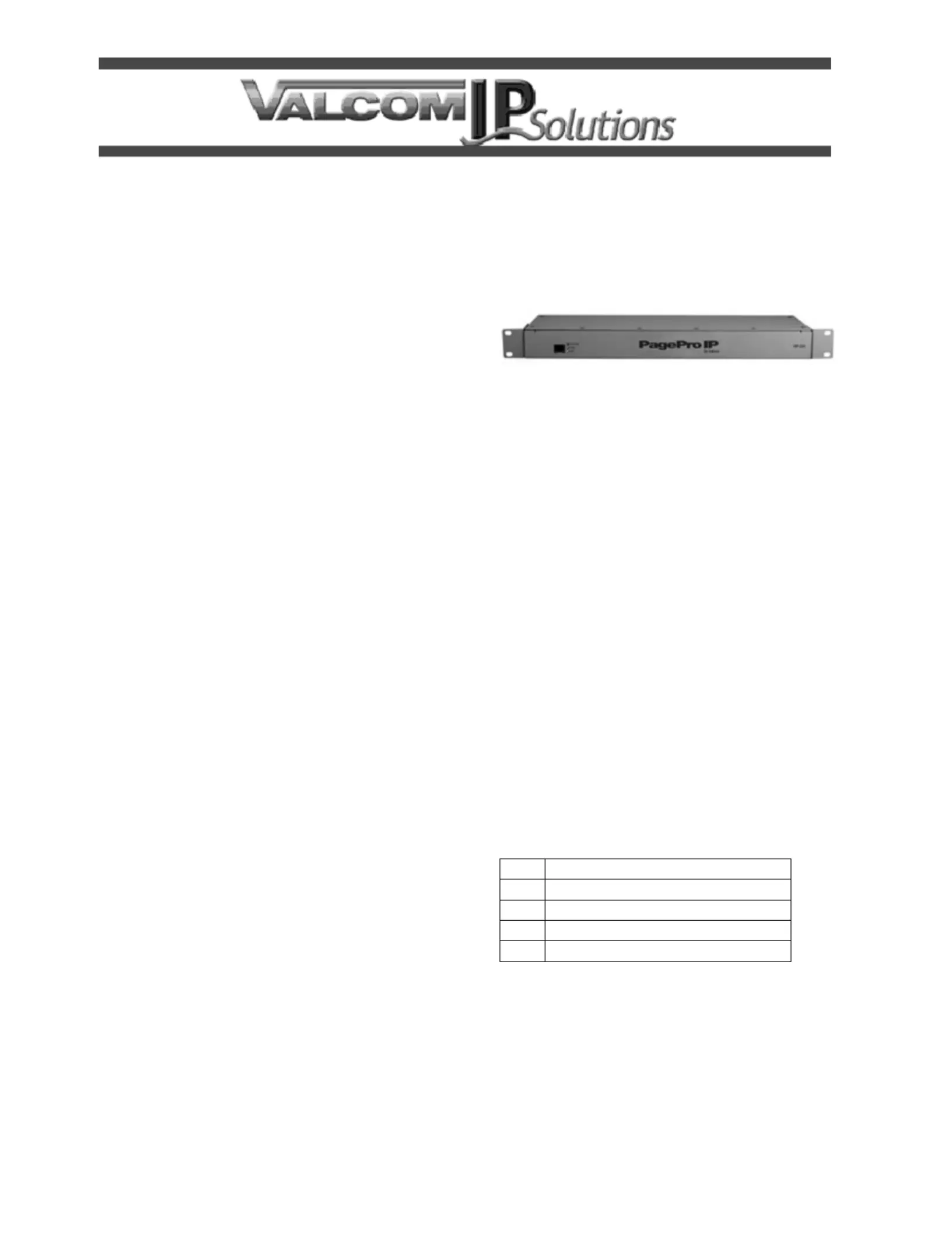
Valcom VIP-201 Manual
Læs gratis den danske manual til Valcom VIP-201 (4 sider) i kategorien Server. Denne vejledning er vurderet som hjælpsom af 7 personer og har en gennemsnitlig bedømmelse på 5.0 stjerner ud af 4 anmeldelser.
Har du et spørgsmål om Valcom VIP-201, eller vil du spørge andre brugere om produktet?
Produkt Specifikationer
| Mærke: | Valcom |
| Kategori: | Server |
| Model: | VIP-201 |
| Produktfarve: | Sølv |
| Relativ luftfugtighed ved drift (H-H): | 0 - 85 % |
| Ethernet LAN-porte (RJ-45): | 1 |
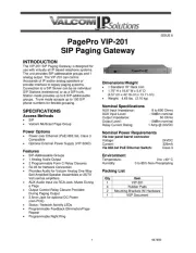
| Dimensioner (BxDxH): | 421.6 x 137.1 x 45.7 mm |
| Udgangsspænding: | 24 V |
| Understøttede protokoller: | IETF SIP (RFC3261), IETF IGMP 3 (RFC3376), IETF RTP (RFC1889), IETF RFC2833\nDHCP, NTP |
Har du brug for hjælp?
Hvis du har brug for hjælp til Valcom VIP-201 stil et spørgsmål nedenfor, og andre brugere vil svare dig
Server Valcom Manualer

Server Manualer
- Toshiba
- Lenovo
- TRENDnet
- Cisco
- MvixUSA
- Analog Way
- SEH
- WyreStorm
- HGST
- ACTi
- Promise Technology
- Allnet
- NEC
- Abus
- Areca
Nyeste Server Manualer