rev. 6/15/2021 FHS, MANUAL.doc
TABLE OF CONTENTS Copyright 2021 Vestil Manufacturing Co. Page 1 of 16
FHS-SERIES STEEL FIXED HEIGHT GANTRY CRANES
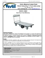
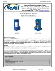
Receiving Instructions
After delivery, remove the packaging from the product. Inspect the product closely to determine whether it
sustained damage during transport. If damage is discovered, record a complete description of it on the bill of lading. If
the product is undamaged, discard the packaging.
NOTE: The end-user is solely responsible for confirming that product design, use, and maintenance comply with laws,
regulations, codes, and mandatory standards applied where the product is used.
Technical Service & Replacement Parts
For answers to questions not addressed in these instructions and to order replacement parts, labels, and accessories,
call our Technical Service and Parts Department at (260) 665-7586. The department can also be contacted online at
http://www.vestilmfg.com/parts_info.htm.
Electronic copies of Instruction Manuals
Additional copies of this instruction manual may be downloaded from https://www.vestil.com/page-manuals.php.
Vestil Manufacturing Corp.
2999 North Wayne Street, P.O. Box 507, Angola, IN 46703
Telephone: (260) 665-7586 -or- Toll Free (800) 348-0868
Fax: (260) 665-1339
Url: www.vestilmfg.com Email: info@vestil.com
Specifications……………………...…….
Fig. A Exploded parts diagram FHS-2-10, FHS-2-15, & FHS-2-20…..….…
Signal Words…..…………….……….......
Fig. B Exploded parts diagram FHS-4-10, FHS-4-15, & FHS-4-20…...…....
Safety Instructions..……………………..
Fig. C Exploded parts diagram FHS-6-10, FHS-6-15, & FHS-6-20…….….
Assembling the Crane……….……..
Fig. D Exploded parts diagram FHS-8-10, FHS-8-15, & FHS-8-20………...
Using the Crane..……………..…..……..
Fig. E Exploded parts diagram FHS-10-10 & FHS-10-15…………………..
Proper Loading………………………….
Fig. 1A: Upright-to-leg assembly connections…………………....……….
Festoon Kit…………………..……………
Fig. 1B: Beam Clamp-to-Bracket Connection…………………………….
Record of Satisfactory Condition…….
Fig. 2A: Beam clamp connection...…………………………....……...……
National Standards……………………..
Fig. 2B: Exploded Parts View of Beam Clamp Connection to Bracket
Inspections & Maintenance………..…
Fig. 5: Caster attachment…………………………….....……………………
Labeling Diagram……………………….
Fig. 6: Proper loading…………………………………………………………..
Limited Warranty………………….……..